vii IPPC-5211WS Series User Manual
Contents
Chapter 1 General Information ............................1
1.1 Introduction ...............................................................................................2
1.2 Specifications............................................................................................2
1.2.1 System Kernel...............................................................................2
1.2.2 I/O Ports........................................................................................2
1.2.3 O/S support...................................................................................2
1.2.4 Safety and Environment................................................................3
1.3 LCD Specifications....................................................................................3
1.4 Touchscreen Specifications ......................................................................4
1.5 Power........................................................................................................4
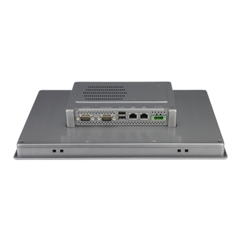
1.6 I/O Ports Arrangement ..............................................................................4
Figure 1.1 I/O Port Arrangement .................................................4
1.7 Mounting Type ..........................................................................................5
1.7.1 VESA mounting.............................................................................5
1.7.2 Foot system mounting...................................................................5
1.7.3 Arm system mounting...................................................................5
1.8 Dimensions ...............................................................................................6
Figure 1.2 IPPC-5211WS Dimensions ........................................6
Chapter 2 System Setup.......................................7
2.1 System Setup............................................................................................8
Figure 2.1 Unpack the Package ..................................................8
Figure 2.2 Power Connector and Power Lines............................9
Figure 2.3 Power Receptor & Button Pin Assignment.................9
2.1.1 Installing the Drivers .....................................................................9
2.2 Transport and Unpacking........................................................................10
2.3 Mounting Type ........................................................................................10
2.3.1 VESA mounting...........................................................................10
2.3.2 Foot system mounting.................................................................11
2.3.3 Arm system mounting.................................................................12
Chapter 3 Features in Windows Embedded .....13
3.1 Features in Windows Embedded Platform..............................................14
3.2 Enhanced Write Filter (EWF) ..................................................................14
3.3 File-Based Write Filter (FBWF)...............................................................16
3.4 HORM .....................................................................................................17
3.5 UWF.......................................................................................................18
Appendix A Serial Port Settings ...........................19
A.1 Jumper, Dip switch and Connector location............................................20
A.1.1 Top..............................................................................................20
A.1.2 Bottom.........................................................................................21
A.2 Jumper setting and Description...............................................................22
A.2.1 CMOS Clear Function (CN1)......................................................22
A.3 Switch Setting .........................................................................................22
A.3.1 Termination Resistor Select (SW3).............................................23
A.4 Connector Pin Definition .........................................................................23
A.4.1 SATA connector (CN12).............................................................23
A.4.2 SATA Power connector (CN13)..................................................24
