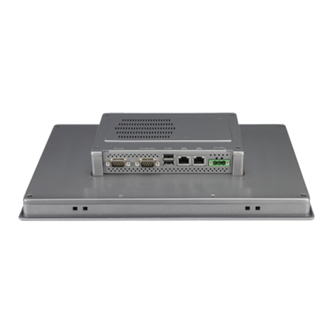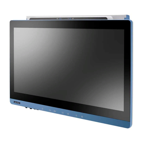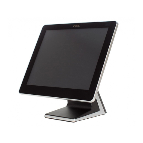
vii PPC-3150SW_3180SW User Manual
Contents
Chapter 1 General Information ............................1
1.1 Introduction ............................................................................................... 2
1.2 Key Features............................................................................................. 2
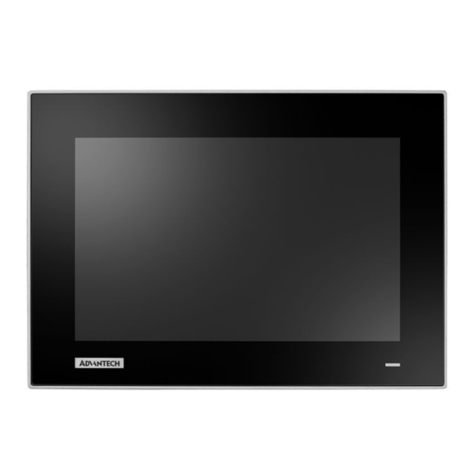
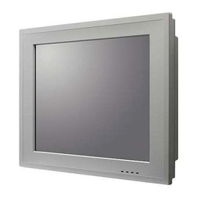
1.3 Front Panel................................................................................................ 2
Figure 1.1 Front Panel ................................................................. 2
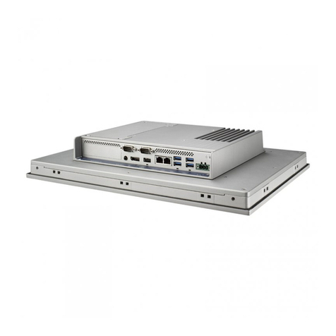
1.4 Rear Panel ................................................................................................ 3
Figure 1.2 Rear Panel.................................................................. 3
1.5 Dimensions ............................................................................................... 4
Figure 1.3 PPC-3150SW-PN4A Dimensions............................... 4
Figure 1.4 PPC-3180SW-PN4A Dimensions............................... 4
1.6 Specifications ............................................................................................ 5
1.7 Ordering Information ................................................................................. 6
Chapter 2 System Installation and Setup ...........7
2.1 Quick System Tour.................................................................................... 8
Figure 2.1 Front View .................................................................. 8
Figure 2.2 Rear View ................................................................... 8
Figure 2.3 I/O Ports ..................................................................... 9
2.2 Installation Procedures.............................................................................. 9
2.2.1 HDD Installation ............................................................................ 9
2.2.2 mSATA Installation ..................................................................... 11
2.2.3 Memory Card Installation ............................................................ 12
2.2.4 Wireless LAN Module Installation ............................................... 13
2.3 System Mounting .................................................................................... 15
2.3.1 Wall Mounting ............................................................................. 15
Figure 2.4 Wall Mount Plate ...................................................... 15
Figure 2.5 Rear Panel Screw Locations .................................... 16
Figure 2.6 Wall Mounting........................................................... 16
Figure 2.7 Securing the Panel PC ............................................. 17
2.3.2 Panel Mounting ........................................................................... 17
Figure 2.8 Hook Brackets for Panel Mounting ........................... 17
Figure 2.9 Hook Bracket Location ............................................. 17
Figure 2.10Fastening Hook Bracket Screws .............................. 18
Figure 2.11Panel Mount Rear View............................................ 18
2.3.3 Arm Mounting.............................................................................. 19
Figure 2.12Arm Mount for Panel PCs......................................... 19
2.3.4 Stand Mounting........................................................................... 20
Figure 2.13VESA Mount Screw Holes........................................ 20
Figure 2.14Securing the VESA Mount Base............................... 21
Figure 2.15Securing the VESA Mount Bracket........................... 21
Figure 2.16Stand Mount Hinge Cover ........................................ 22
Figure 2.17Completed Stand Mount........................................... 22
Chapter 3 Jumper Setting ..................................23
3.1 Motherboard Layout ................................................................................ 24
Figure 3.1 Motherboard Layout Diagram................................... 24
3.2 Jumpers and Connectors ........................................................................ 25
3.3 External COM Port Pin Definition............................................................ 27
3.3.1 COM1: RS-232; COM2: RS-232/422/485................................... 27
