manuals.online logo
Brands
  1. Home
  2. •
  3. Brands
  4. •
  5. AETEK
  6. •
  7. Switch
  8. •
  9. AETEK D60-044-30 User manual

AETEK D60-044-30 User manual

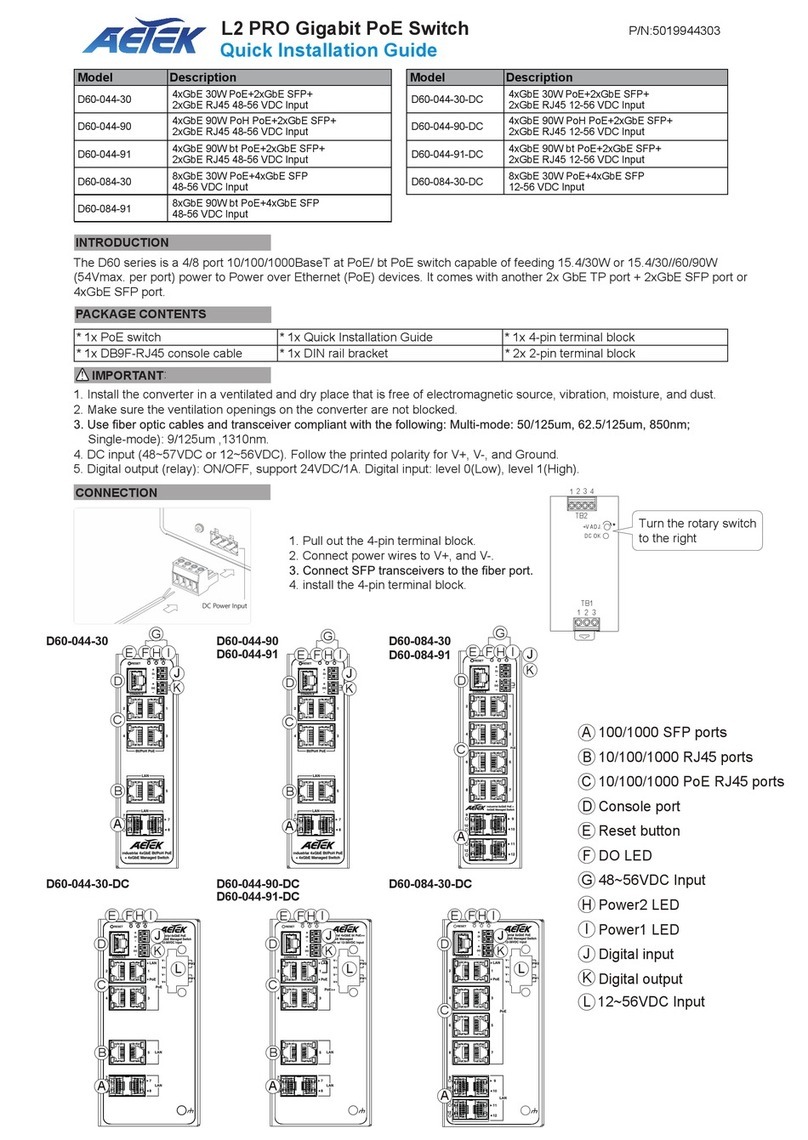
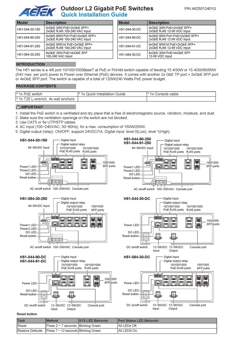
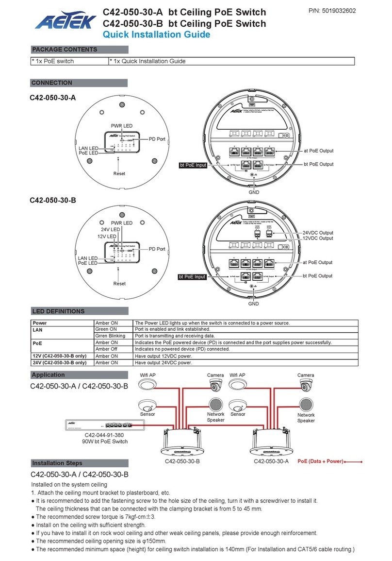
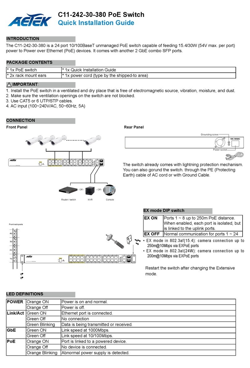
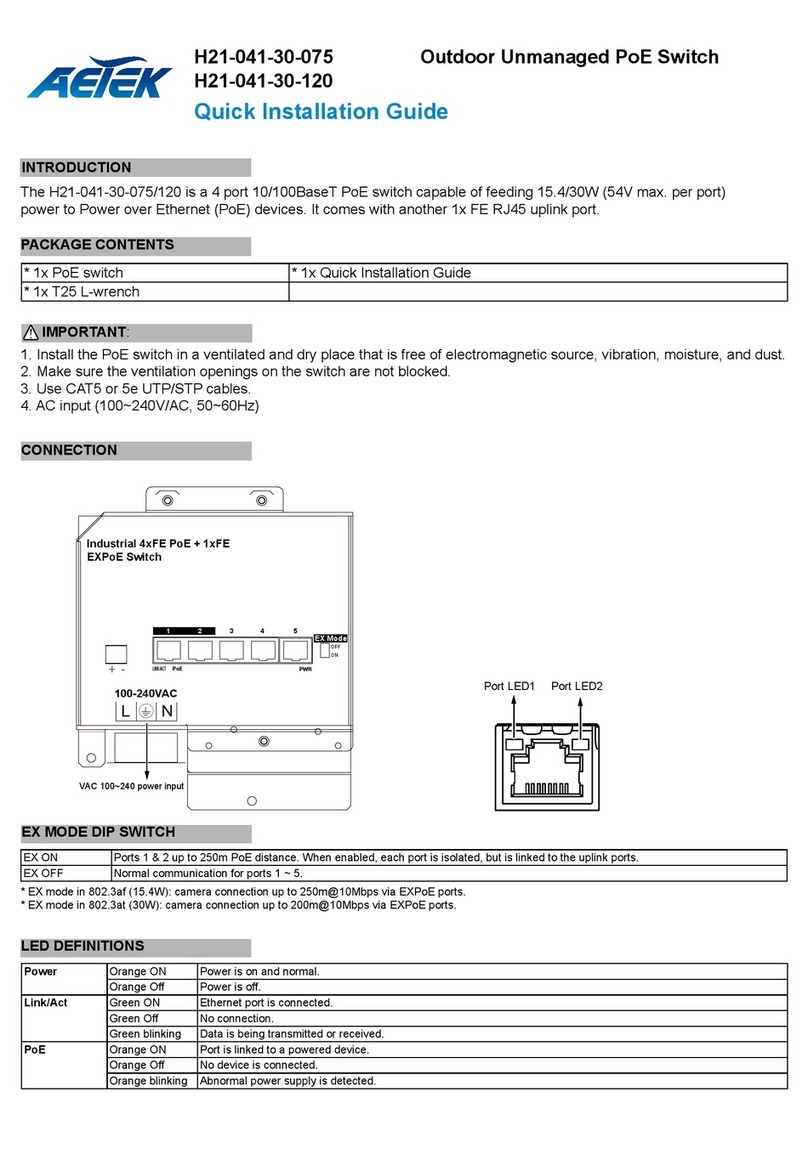
1. Install the converter in a ventilated and dry place that is free of electromagnetic source, vibration, moisture, and dust.
2. Make sure the ventilation openings on the converter are not blocked.
Single-mode): 9/125um ,1310nm.
4. DC input (48~57VDC or 12~56VDC). Follow the printed polarity for V+, V-, and Ground.
5. Digital output (relay): ON/OFF, support 24VDC/1A. Digital input: level 0(Low), level 1(High).
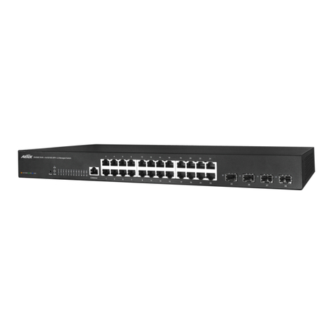
D60-044-30 D60-044-91 D60-084-30
L2 PRO Gigabit PoE Switch
Quick Installation Guide
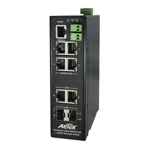
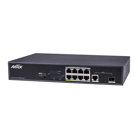
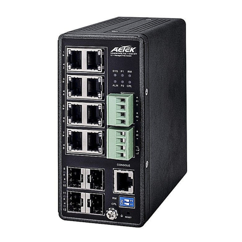
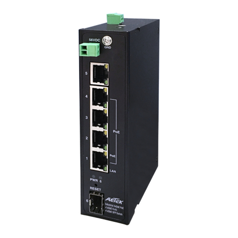
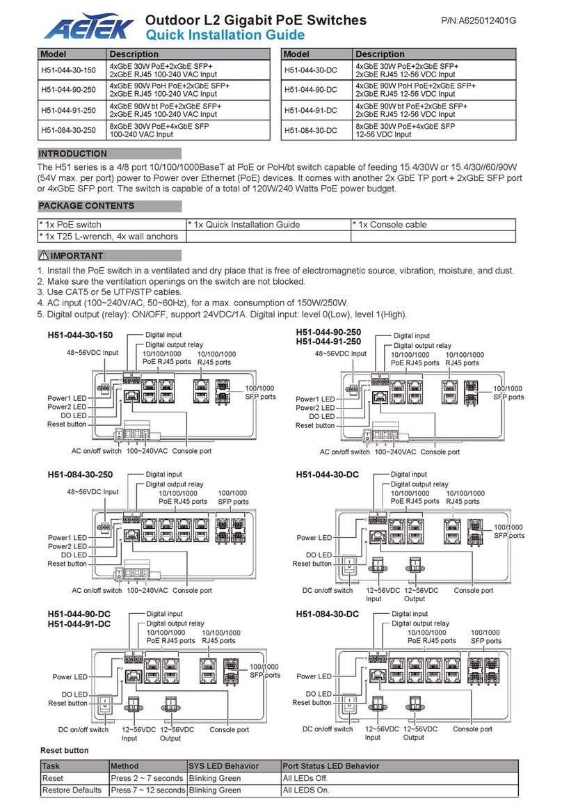
The D60 series is a 4/8 port 10/100/1000BaseT at PoE/ bt PoE switch capable of feeding 15.4/30W or 15.4/30//60/90W
(54Vmax. per port) power to Power over Ethernet (PoE) devices. It comes with another 2x GbE TP port + 2xGbE SFP port or
4xGbE SFP port.
IMPORTANT:
INTRODUCTION
CONNECTION
* 1x PoE switch * 1x Quick Installation Guide * 1x 4-pin terminal block
* 2x 2-pin terminal block
* 1x DB9F-RJ45 console cable * 1x DIN rail bracket
PACKAGE CONTENTS
1. Pull out the 4-pin terminal block.
2. Connect power wires to V+, and V-.
4. install the 4-pin terminal block.
10/100/1000
PoE RJ45 ports
100/1000
SFP ports
Digital input
Digital output relay
Console port
10/100/1000
PoE RJ45 ports
100/1000
SFP ports
10/100/1000
RJ45 ports
100/1000
SFP ports
10/100/1000
RJ45 ports
10/100/1000
PoE RJ45 ports
Console port
Console port
Power1 LED
Power2 LED
48~56VDC Input
DO LED
Reset button
Digital input
Digital output relay
Digital input
Digital output relay
P/N:A625013801G
Model Description
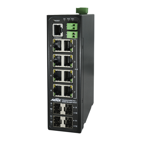
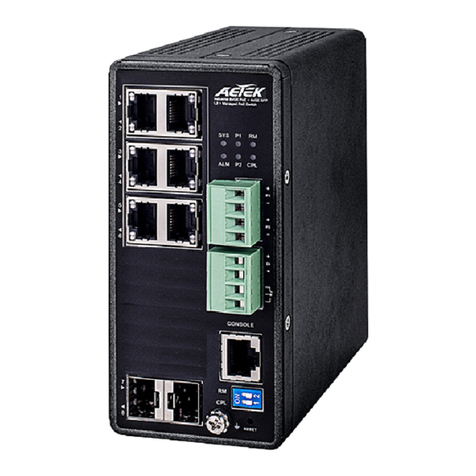
D60-044-30 4xGbE 30W PoE+2xGbE SFP+2xGbE RJ45
48-56 VDC Input
D60-044-91 4xGbE 90W bt PoE+2xGbE SFP+2xGbE RJ45
48-56 VDC Input
D60-084-30 8xGbE 30W PoE+4xGbE SFP
48-56 VDC Input
Model Description
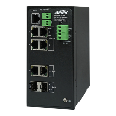
D60-044-30-DC 4xGbE 30W PoE+2xGbE SFP+2xGbE RJ45
12-56 VDC Input
D60-044-91-DC 4xGbE 90W bt PoE+2xGbE SFP+2xGbE RJ45
12-56 VDC Input
D60-084-30-DC 8xGbE 30W PoE+4xGbE SFP
12-56 VDC Input
Power1 LED
Power2 LED
48~56VDC Input
DO LED
Reset button
Power1 LED
Power2 LED
48~56VDC Input
DO LED
Reset button
D60-044-30-DC D60-044-91-DC D60-084-30-DC
10/100/1000
PoE RJ45 ports
100/1000
SFP ports
Console port Digital input
Digital output
relay
Power1 LED
Power2 LED
12~56VDC Input
DO LED
Reset button
10/100/1000
PoE RJ45 ports
100/1000
SFP ports
Console port Digital input
Digital output
relay
Power1 LED
Power2 LED
12~56VDC Input
DO LED
Reset button
10/100/1000
PoE RJ45 ports
100/1000
SFP ports
Console port Digital input
Digital output
relay
Power1 LED
Power2 LED
12~56VDC Input
DO LED
Reset button
IP Address 192.168.1.1
Subnet Mask 255.255.255.0
User Name
Password
DEFAULTS
Power LEDs
LED Color State Description
Power1 Green On Powered on correctly.
Off Not receiving power from power1.
Power2 Green On Powered on correctly.
Off Not receiving power from power1.
DO LED
LED Color State Description
System Yellow On DO ON
Off DO OFF
Baud rate 115200
Stop bits 1
Data bits 8
Parity N
Flow control none
Console Port Defaults
Port Status LEDs
LED Color State Description
RJ45 Ports
Up (PoE)
Amber On The port is enabled and supplying power to connected device.
- Off The port has no active connection, or it is not connected to a PoE PD device. Otherwise, the port may
have been disabled through the switch user interface.
RJ45 Ports
Down (LAN)
Green On The port is enabled and established a link to connected device.
- Off The port has no active network connection, or it has no established link to connected device.
Otherwise, the port may have been disabled through the switch user interface.
SFP Ports Green On The port is enabled and supplying power to connected device.
Green Blinking
Green Blinking
The port is transmitting/receiving packets.
- Off The port has no active network connection, or it has no established link to connected device.
Otherwise, the port may have been disabled through the switch user interface.
Reset button
Task Method SYS LED Behavior Port Status LED Behavior
Reset Press 2 ~ 7 seconds Blinking Green All LEDs Off.
Restore Defaults Press 7 ~ 12 seconds Blinking Green All LEDS On.
DIN Rail Installation
admin
admin
DI+
DI-
DO+
DO-
12VDC
Switch
+ -
12V device
+ -
100-240VAC Input
DI/DO Connection Diagram
100-240VAC Input
DI+
DI-
DO+
DO-
Switch
AC or DC
device
12V Relay AC or DC
- -
+ +
AC or DC
Power
12VDC
+ -
DI/DO Connection Diagram w/ AC or DC Relay
AETEK INC.
6F, No.192-1, Lien-Cheng Rd., Chung-Ho, New TaipeiCity, 235, Taiwan, R.O.C.
|T:+886-2-82452822|W:www.aetektec.com|E:[email protected]om
Copyright © 2022 AETEK INC. All rights reserved.
Other manuals for D60-044-30

1

This manual suits for next models

6

Other AETEK Switch manuals

AETEK H70-044-30 User manual

AETEK

AETEK H70-044-30 User manual

AETEK H30-042-30 User manual

AETEK

AETEK H30-042-30 User manual

AETEK D51-084-30 D51-044-30-DC User manual

AETEK

AETEK D51-084-30 D51-044-30-DC User manual

AETEK D51-044-30 User manual

AETEK

AETEK D51-044-30 User manual

AETEK C11-082-30-120 User manual

AETEK

AETEK C11-082-30-120 User manual

AETEK D60-044-90 User manual

AETEK

AETEK D60-044-90 User manual

AETEK H51-044-91-DC User manual

AETEK

AETEK H51-044-91-DC User manual

AETEK C62-050-30-A User manual

AETEK

AETEK C62-050-30-A User manual

AETEK H40-044-30-150-V3 User manual

AETEK

AETEK H40-044-30-150-V3 User manual

AETEK H21-041-30-075 User manual

AETEK

AETEK H21-041-30-075 User manual

AETEK H60-044-30-150 User manual

AETEK

AETEK H60-044-30-150 User manual

AETEK H21-082-31-150 User manual

AETEK

AETEK H21-082-31-150 User manual

AETEK C70-00A-01 User manual

AETEK

AETEK C70-00A-01 User manual

AETEK C11-082-31-120 User manual

AETEK

AETEK C11-082-31-120 User manual

AETEK H40-022-90-120 User manual

AETEK

AETEK H40-022-90-120 User manual

AETEK C42-050-30-A User manual

AETEK

AETEK C42-050-30-A User manual

AETEK D51-044-91 User manual

AETEK

AETEK D51-044-91 User manual

AETEK C50-082-30-130 User manual

AETEK

AETEK C50-082-30-130 User manual

AETEK H40-022-91-120-A-V2 User manual

AETEK

AETEK H40-022-91-120-A-V2 User manual

AETEK C11-082-32-120 User manual

AETEK

AETEK C11-082-32-120 User manual

AETEK H51-044-30-150 User manual

AETEK

AETEK H51-044-30-150 User manual

AETEK H21-041-30-075 User manual

AETEK

AETEK H21-041-30-075 User manual

AETEK H60-044-90-250 User manual

AETEK

AETEK H60-044-90-250 User manual

AETEK H40 Series User manual

AETEK

AETEK H40 Series User manual

Popular Switch manuals by other brands

Redbird TD quick start

Redbird

Redbird TD quick start

Extricom EXWO-404 user guide

Extricom

Extricom EXWO-404 user guide

Apollo SA5900-011 installation guide

Apollo

Apollo SA5900-011 installation guide

Cisco CDB-8U installation guide

Cisco

Cisco CDB-8U installation guide

Lutron Electronics Maestro MS-OPS6M2U-DV  Series manual

Lutron Electronics

Lutron Electronics Maestro MS-OPS6M2U-DV Series manual

ATEN ALTUSEN KL1508A Quick start guides

ATEN

ATEN ALTUSEN KL1508A Quick start guides

CyberPower CP CP-H411 CP-H411 quick start guide

CyberPower

CyberPower CP CP-H411 CP-H411 quick start guide

Xcellon SH10-7H3HC-2 quick start guide

Xcellon

Xcellon SH10-7H3HC-2 quick start guide

Quest Engineering QS53E user manual

Quest Engineering

Quest Engineering QS53E user manual

Lightware UMX-HDMI-140 quick start guide

Lightware

Lightware UMX-HDMI-140 quick start guide

Exsys EX-1112HMS manual

Exsys

Exsys EX-1112HMS manual

AJA D5PSW Installation and operation guide

AJA

AJA D5PSW Installation and operation guide

Siemens HUB-4 installation instructions

Siemens

Siemens HUB-4 installation instructions

Pathway connectivity solutions 1016 manual

Pathway connectivity solutions

Pathway connectivity solutions 1016 manual

Pilz PSEN 1.2p-25 operating instructions

Pilz

Pilz PSEN 1.2p-25 operating instructions

Surecom EP-808X-R user guide

Surecom

Surecom EP-808X-R user guide

Spectra Engineering RELM BK RADIO MXACU Technical manual

Spectra Engineering

Spectra Engineering RELM BK RADIO MXACU Technical manual

RTI AD-16x Installation and operation

RTI

RTI AD-16x Installation and operation

manuals.online logo
manuals.online logoBrands
  • About & Mission
  • Contact us
  • Privacy Policy
  • Terms and Conditions

Copyright 2025 Manuals.Online. All Rights Reserved.