manuals.online logo
Brands
  1. Home
  2. •
  3. Brands
  4. •
  5. AETEK
  6. •
  7. Switch
  8. •
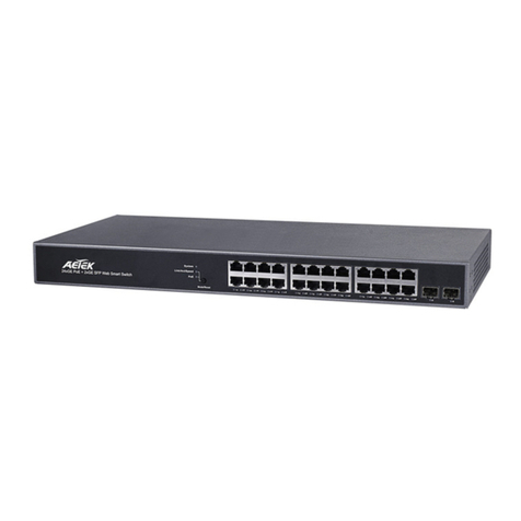
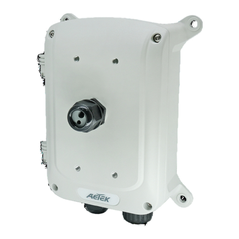
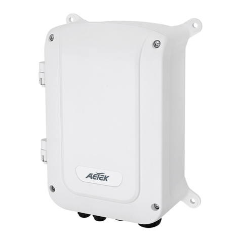
  9. AETEK H70-044-30 User manual

AETEK H70-044-30 User manual

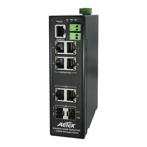
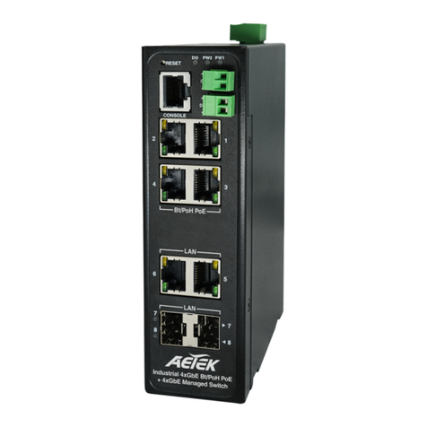
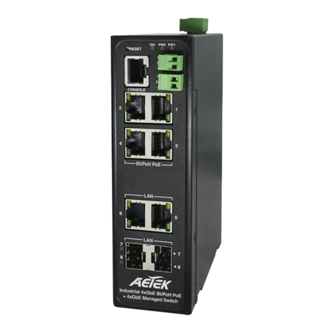
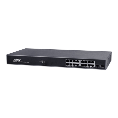
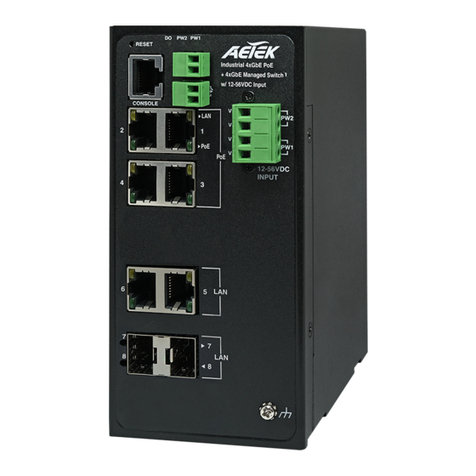
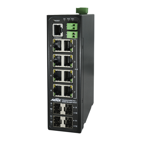
Industrial 4xGbE PoE +
4xGbE Manaaged Switch
10/100/1000
RJ45 ports
100/1000
SFP ports
System LED
Power1 LED
Ring Master LED
Rapid Chain LED
Power2 LED
Alarm LED
DC 54V power input
Digital input
Digital output relay
Console port
DIP switch (Ring Settings)
Reset button
Ground screw
1. Install the converter in a ventilated and dry place that is free of electromagnetic source, vibration, moisture, and dust.
2. Make sure the ventilation openings on the converter are not blocked.
Single-mode): 9/125um ,1310nm.
4. DC input (48~57VDC). Follow the printed polarity for V+, V-, and Ground.
H70-044-30 Industrial L2+ Managed GbE PoE Switch
Quick Installation Guide
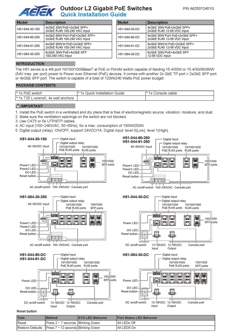
The H70-044-30 L2+ managed switch supports 4x GbE PoE, 2x GbE RJ45, 2x GbE SFP, and 1x RJ45 console port. It is
IEEE 802.3at/af compliant and delivers the real full-load output of 120W on 4 PoE ports (30W per port).This industrial
L2+ managed switch also features a wide operating temperature range from -40ºC to 75ºC for harsh environment.
IMPORTANT:
INTRODUCTION
CONNECTION
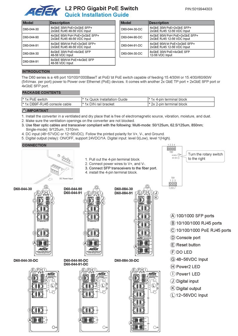
* 1x PoE switch * 1x Quick Installation Guide * 2x 4-pin terminal block
* 1x DB9F-RJ45 console cable * 1x DIN rail bracket
PACKAGE CONTENTS
IP Address 192.168.1.1
Subnet Mask 255.255.255.0
User Name admin
Password admin
DEFAULTS
1. Pull out the 4-pin terminal block.
2. Connect power wires to V+, and V-.
4. install the 4-pin terminal block.
NOTE: Digital output (relay): 24VDC/1A. Digital input: level 0(Low) -> 0V to 6V,
level 1(High) -> 10V to 24V.
Power LEDs
LED Color State Description
Power1 Green On Powered on correctly.
Off Not receiving power from power1.
Power2 Green On Powered on correctly.
Off Not receiving power from power1.
System LED
LED Color State Description
System Green On Switch is ready.
Off Switch is not ready.
Alarm LED
LED Color State Description
Alarm Red On Abnormal state, such temperature,
voltage, or DC power, has occurred.
Off System is normal.
Ring Master and Rapid Chain LEDs
LED Color State Description
RM
(Ring Master)
Green On Ring Master has been detected.
Amber On Ring Member has been detected.
- Off Disabled.
CPL
(Rapid Chain)
Green On Rapid Chain has been detected (Active path).
Amber On Rapid Chain has been detected (Backup path).
Blinking Error, there is no correspondent Rapid Chain switch found.
- Off Disabled.
Baud rate 115200
Stop bits 1
Data bits 8
Parity N
Flow control none
Console Port Defaults
AETEK INC.
3F, No.192, Lien-Cheng Rd., Chung-Ho, New TaipeiCity, 235, Taiwan, R.O.C.
|T:+886-2-82452822|W:www.aetektec.com|E:[email protected]om
Copyright © 2018 AETEK INC. All rights reserved.
Port Status LEDs
LED Color State Description
RJ45 Ports
Up
Green On The port is enabled and established a link to connected device, and the speed is 1000Mbps.
Green Blinking The port is transmitting/receiving packets, and the speed is 1000Mbps.
Amber On The port is enabled and established a link to connected device, and the speed is 10/100Mbps.
Amber Blinking The port is transmitting/receiving packets, and the speed is 10/100Mbps.
- Off The port has no active network connection, or it has no established link to connected device.
Otherwise, the port may have been disabled through the switch user interface.
RJ45 Ports
Down
Green On The port is enabled and supplying power to connected device.
Amber On An abnormal state, such as overload status, has been detected in the switch.
- Off The port has no active connection, or it is not connected to a PoE PD device. Otherwise, the port may
have been disabled through the switch user interface.
SFP Ports Green On The port is enabled and established a link to connected device, and the speed is 1000Mbps.
Green Blinking The port is transmitting/receiving packets, and the speed is 1000Mbps.
Amber On The port is enabled and established a link to connected device, and the speed is 100Mbps.
Amber Blinking The port is transmitting/receiving packets, and the speed is 100Mbps.
- Off The port has no active network connection, or it has no established link to connected device.
Otherwise, the port may have been disabled through the switch user interface.
Reset button
Task Method SYS LED Behavior Port Status LED Behavior
Reset Press 2 ~ 7 seconds Blinking Green All LEDs Off.
Restore Defaults Press 2 ~ 7 seconds Blinking Green All LEDS On.
DIN Rail Installation
DIP Switch
O N
1
2
RM
CPL
Mode RM CPL Rapid Ring status 1st Port 2nd Port LED RM LED CPL
HW
Control
Off Off Single Ring member The largest Odd port
number
The largest Even port
number
Amber Off
HW
Control
On Off Single Ring Master The largest Odd port
number
The largest Even port
number
Green Off
HW
Control
Off On Rapid Chain The largest Odd port
number
The largest Even port
number
Off Green (Active path);
Amber (Backup path)
SW
Control
On On Rapid Ring settings
by SW
----
RM: Ring Master
CPL: Rapid Chain

Other AETEK Switch manuals

AETEK H21-082-31-150 User manual

AETEK

AETEK H21-082-31-150 User manual

AETEK C62-050-30-A User manual

AETEK

AETEK C62-050-30-A User manual

AETEK H40-022-91-120-A-V2 User manual

AETEK

AETEK H40-022-91-120-A-V2 User manual

AETEK H40-022-90-120 User manual

AETEK

AETEK H40-022-90-120 User manual

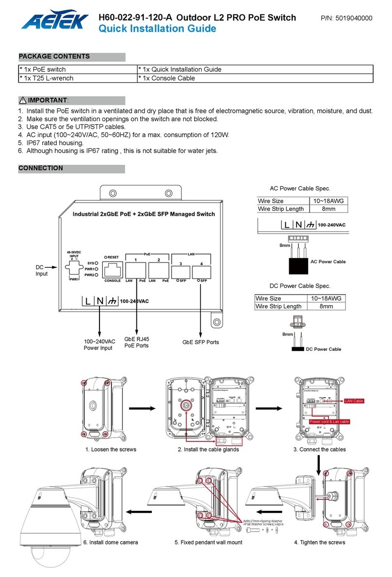
AETEK H60-022-91-120-A User manual

AETEK

AETEK H60-022-91-120-A User manual

AETEK H60-044-30-150 User manual

AETEK

AETEK H60-044-30-150 User manual

AETEK D51-044-90 User manual

AETEK

AETEK D51-044-90 User manual

AETEK H70-044-60 User manual

AETEK

AETEK H70-044-60 User manual

AETEK H70-084-30 User manual

AETEK

AETEK H70-084-30 User manual

AETEK H51-044-91-DC User manual

AETEK

AETEK H51-044-91-DC User manual

AETEK H51-044-30-150 User manual

AETEK

AETEK H51-044-30-150 User manual

AETEK H21-082-31-150 User manual

AETEK

AETEK H21-082-31-150 User manual

AETEK H60-044-90-250 User manual

AETEK

AETEK H60-044-90-250 User manual

AETEK C11-162-30-250 User manual

AETEK

AETEK C11-162-30-250 User manual

AETEK D60-044-30 User manual

AETEK

AETEK D60-044-30 User manual

AETEK H40 Series User manual

AETEK

AETEK H40 Series User manual

AETEK H60-044-30-150 User manual

AETEK

AETEK H60-044-30-150 User manual

AETEK C50-082-30-130 User manual

AETEK

AETEK C50-082-30-130 User manual

AETEK C50 Series User manual

AETEK

AETEK C50 Series User manual

AETEK H51-044-91-250 User manual

AETEK

AETEK H51-044-91-250 User manual

AETEK C11-082-31-120 User manual

AETEK

AETEK C11-082-31-120 User manual

AETEK D51-044-30 User manual

AETEK

AETEK D51-044-30 User manual

AETEK C42-050-30-A User manual

AETEK

AETEK C42-050-30-A User manual

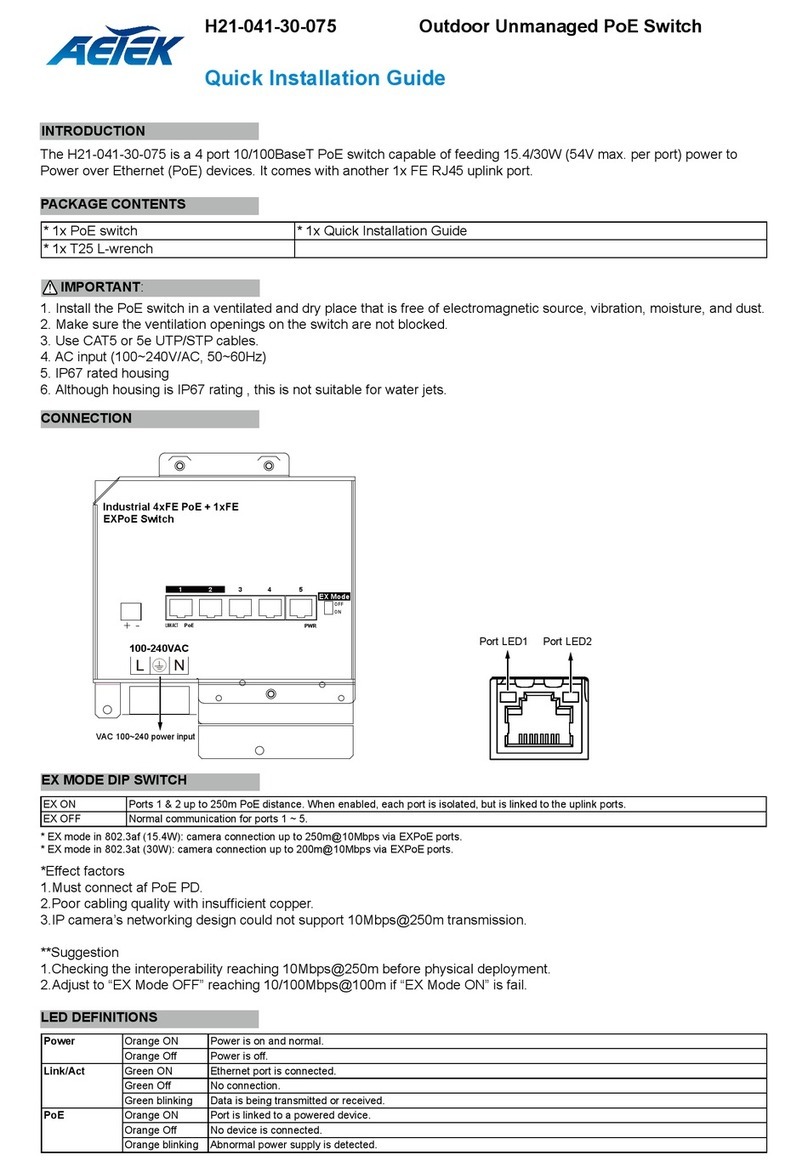
AETEK H21-041-30-120 User manual

AETEK

AETEK H21-041-30-120 User manual

Popular Switch manuals by other brands

Dwyer Instruments W.E. Anderson Flotect L6 Specifications-installation and operating instructions
Dwyer Instruments

Dwyer Instruments W.E. Anderson Flotect L6 Specifications-installation and operating instructions

Brocade Communications Systems ICX 6650 series Security configuration guide

Brocade Communications Systems

Brocade Communications Systems ICX 6650 series Security configuration guide

H3C S6890 Series installation guide

H3C

H3C S6890 Series installation guide

StarTech.com VS221VGA2HD user guide

StarTech.com

StarTech.com VS221VGA2HD user guide

H3C S12500-X Command reference

H3C

H3C S12500-X Command reference

AUVIO 15-318 user guide

AUVIO

AUVIO 15-318 user guide

Matrix Switch Corporation MSC-2HD0832S product manual

Matrix Switch Corporation

Matrix Switch Corporation MSC-2HD0832S product manual

LightPro NXT Switch 195A user manual

LightPro

LightPro NXT Switch 195A user manual

Agilent Technologies E1463A User's manual and scpi programming guide

Agilent Technologies

Agilent Technologies E1463A User's manual and scpi programming guide

Siemens ISGS Operator's manual

Siemens

Siemens ISGS Operator's manual

Panasonic WJ-SW104 operating instructions

Panasonic

Panasonic WJ-SW104 operating instructions

Ubiquiti USW-Flex quick start guide

Ubiquiti

Ubiquiti USW-Flex quick start guide

Renkforce FK-JH-X operating instructions

Renkforce

Renkforce FK-JH-X operating instructions

Emerson PENBERTHY MGS-314L Series Installation, operation and maintenance instructions

Emerson

Emerson PENBERTHY MGS-314L Series Installation, operation and maintenance instructions

TP-Link T2500-28TC installation guide

TP-Link

TP-Link T2500-28TC installation guide

Interlogix IFS NS2052-4P-1T user manual

Interlogix

Interlogix IFS NS2052-4P-1T user manual

Vigitron Vi3003 user manual

Vigitron

Vigitron Vi3003 user manual

Cisco 11506 - CSS Content Services Switch datasheet

Cisco

Cisco 11506 - CSS Content Services Switch datasheet

manuals.online logo
manuals.online logoBrands
  • About & Mission
  • Contact us
  • Privacy Policy
  • Terms and Conditions

Copyright 2025 Manuals.Online. All Rights Reserved.