manuals.online logo
Brands
  1. Home
  2. •
  3. Brands
  4. •
  5. AETEK
  6. •
  7. Switch
  8. •
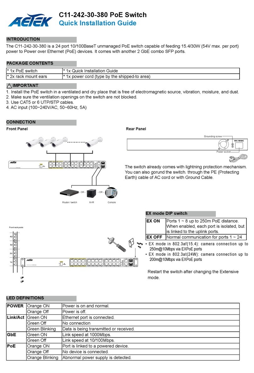
  9. AETEK H40-022-90-120 User manual

AETEK H40-022-90-120 User manual

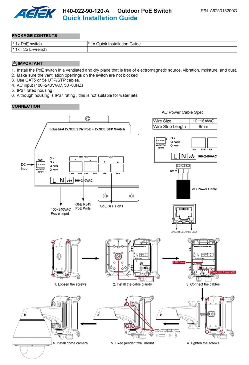
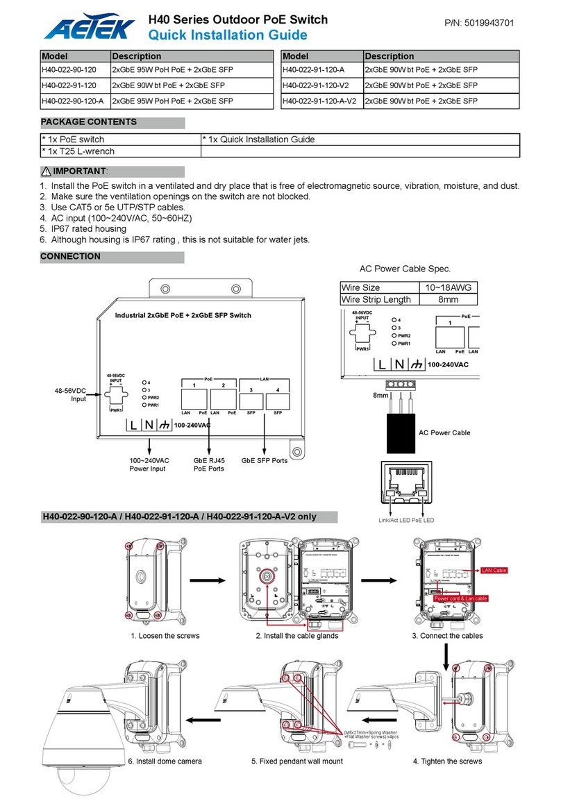
1. Install the PoE switch in a ventilated and dry place that is free of
electromagnetic source, vibration, moisture, and dust.
2. Make sure the ventilation openings on the switch are not blocked.
3. Use CAT5 or 5e UTP/STP cables.
4. AC input (100~240V/AC, 50~60Hz).
5. Although housing is IP67 rating , this is not suitable for water jets.
IMPORTANT:
* 1x PoE switch * 1x Quick Installation Guide * 1x Console cable (H80 only)
* 1x T25 L-wrench, 4x wall anchors
PACKAGE CONTENTS
Quick Installation Guide
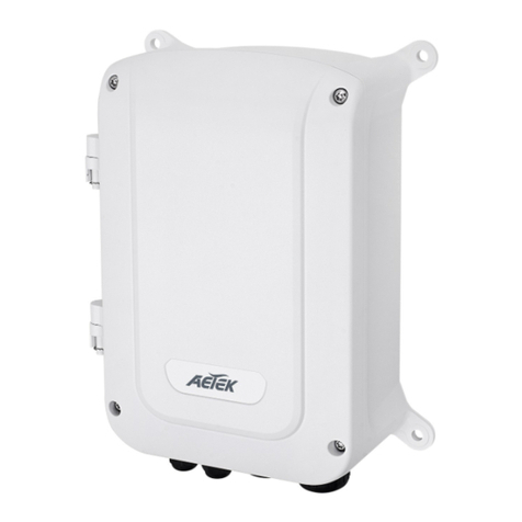
Outdoor Gigabit Ethernet PoE Switch
LED DEFINITIONS
LED DEFINITIONS
P/N: A625012800G
Model Description
H40-022-90-120 2xGbE 95W PoH PoE + 2xGbE SFP
H40-022-91-120 2xGbE 90W bt PoE + 2xGbE SFP
H40-042-30-075 4xGbE 30W PoE + 1xGbE RJ45 + 1xGbE SFP
H40-044-30-150 4xGbE 30W PoE + 2xGbE RJ45 + 2xGbE SFP
H40-044-90-250 4xGbE 95W PoH PoE + 2xGbE RJ45 + 2xGbE SFP
H40-044-91-250 4xGbE 90W bt PoE + 2xGbE RJ45 + 2xGbE SFP
Model Description
H40-082-30-250 8xGbE 30W PoE + 2xGbE SFP
H42-042-30-075 4xGbE 30W PoE + 1xGbE(24VDC/56VDC) PoE
+ 1xGbE SFP
H80-044-30-150 4xGbE 30W PoE + 2xGbE RJ45 + 2xGbE SFP
H80-044-60-250 4xGbE 60W PoE + 2xGbE RJ45 + 2xGbESFP
H80-084-30-250 8xGbE 30W PoE + 4xGbE SFP
6.The cabinet must be grounded using a ground wire
between the ground screw and earth ground.
NOTE: Digital output (relay): 24VDC/1A. Digital input: level 0(Low) -> 0V to 6V, level 1(High) -> 10V to 24V.
Power
PW1/PW2
Green ON Power is on and normal.
SFP port
Green
Green ON Fiber is aeeached.
Grren Flashing Data is being transmitted / received.
LAN ports
Green
Green ON TX link is detected.
Grren Flashing Data is being transmitted or received.
PoE ports
Amber
Amber ON PSE is activated and PD is detected.
Amber OFF PoE OFF
RJ45 port Up Green / Amber Blinks when any trafc is present. The light is green when linking up 1Gbps.
The light is Amber when linking up 10/100Mbps.
RJ45 port
Down
Green / Amber Green is port enabled and supplying power to connected device.
Amber is An abnormal state, such as overload status.
SFP Ports Green / Amber Blinks when any trafc is present. The light is green when linking up 10Gbps.
The light is amber when linking up 1Gbps.
Power Green Powered on correctly is ON.
System Green Switch ready is ON.
Alarm Red Abnormal state, such temperature,voltage, or DC power, has occurred is ON.
LED Color State Description
RM
(Ring Master)
Green On Ring Master has been detected in the switch.
Amber On Ring Member has been detected in the switch.
-Off Disable
CPL
(Rapid Chain)
Green On Rapid Chain has been detected in the switch. (Active path)
Amber On Rapid Chain has been detected in the switch. (Backup path)
Blinking Error: There is no correspondent Rapid Chain Switch found.
-Off Disable
H80 Series
H40 / H42 Series
RESET & RESTORE
RESET
Reset the switch 2 ~ 7 seconds Blinking Green All LEDs are OFF
Restore to defaults 7 ~ 12 seconds Blinking Green All LEDs stay ON
Reset the switch 3 seconds Blinking Green All LEDs off
IP Address 192.168.1.1
Subnet Mask 255.255.255.0
User Name admin
Password admin
Console Port:
Baud rate 115200
Stop bits 1
Data bits 8
Parity N
Flow contro none
DEFAULTS
DIP Switch
O N
1
2
RM
CPL
RM: Ring Master
CPL: Rapid Chain
H40-022-90-120 / H40-022-91-120
8mm
AC Power Cable
AC Power Cable Spec.
Wire Size 10~18AWG
Wire Strip Length 8mm
DC
Input
100~240VAC
Power Input
GbE RJ45
PoE Ports GbE SFP Ports
Industrial 4xGbE PoE
+1xGbE RJ45
+1xGbE SFP Switch
Port 1~4
GbE RJ45
PoE ports GbE SFP ports
100~240VAC power input
Reset button

Port 5
GbE RJ45
DC
Input
H40-042-30-075
H40-044-30-150 / H40-044-90-250 / H40-044-91-250
DC input LEDs
VAC 100~240 power input
Reset button
GbE RJ45
PoE ports
GbE RJ45
Data ports
GbE SFP
Data ports
H40-082-30-250
DC input LEDs
VAC 100~240 power input
Reset button
GbE RJ45
PoE ports
GbE SFP
Data ports
H42-042-30-075
Port 1~4
GbE RJ45
PoE ports GbE SFP ports
100~240VAC power input
Reset button
Port 5
GbE RJ45
24V/56VDC PoE port
Port 5
56VDC
24VDC
OFF
Adjustable Output PoE
DC
Input
GbE SFP ports
DC input
LEDs
100~240 power input
Reset button
GbE RJ45
data ports
GbE RJ45
PoE ports
DI/DO Console
port
DIP switch
ring setting
H80-044-30-150 / H80-044-60-250
GbE SFP ports
DC input
LEDs
VAC 100~240 power input
Reset button
GbE RJ45
PoE ports
DI/DO Console
port
DIP switch
ring setting
H80-084-30-250
Use the included M8 hex socket screws to secure the Outdoor
PoE Switch to a pole-mount or corner mount bracket.
3/4” conduit
M8
INSTALLATION
The mounting hole denition is illustrated below.
The same mounting hole pattern apply to all pole-mount and
corner-mount brackets.
AETEK INC.
3F, No.192, Lien-Cheng Rd., Chung-Ho, New Taipei City, 235, Taiwan, R.O.C.
|T:+886-2-82452822|W: www.aetektec.com|E:[email protected]
All specications are subject to change without noice.
Copyright © 2021 AETEK INC. All rights reserved.

This manual suits for next models

10

Other AETEK Switch manuals

AETEK H21-041-30-075 User manual

AETEK

AETEK H21-041-30-075 User manual

AETEK C60-00F-01 User manual

AETEK

AETEK C60-00F-01 User manual

AETEK D51-044-30 User manual

AETEK

AETEK D51-044-30 User manual

AETEK H51-044-91-250 User manual

AETEK

AETEK H51-044-91-250 User manual

AETEK C11-162-30-250 User manual

AETEK

AETEK C11-162-30-250 User manual

AETEK H51-044-30-150 User manual

AETEK

AETEK H51-044-30-150 User manual

AETEK H60-022-91-120-A User manual

AETEK

AETEK H60-022-91-120-A User manual

AETEK H40 Series User manual

AETEK

AETEK H40 Series User manual

AETEK C11-082-32-120 User manual

AETEK

AETEK C11-082-32-120 User manual

AETEK D60-044-90 User manual

AETEK

AETEK D60-044-90 User manual

AETEK H21-041-30-120 User manual

AETEK

AETEK H21-041-30-120 User manual

AETEK H60-044-30-150 User manual

AETEK

AETEK H60-044-30-150 User manual

AETEK H40-022-90-120-A User manual

AETEK

AETEK H40-022-90-120-A User manual

AETEK H70-084-30 User manual

AETEK

AETEK H70-084-30 User manual

AETEK C70-00A-01 User manual

AETEK

AETEK C70-00A-01 User manual

AETEK H21-041-30-075 User manual

AETEK

AETEK H21-041-30-075 User manual

AETEK H60-044-90-250 User manual

AETEK

AETEK H60-044-90-250 User manual

AETEK H21-082-31-150 User manual

AETEK

AETEK H21-082-31-150 User manual

AETEK C50-082-30-130 User manual

AETEK

AETEK C50-082-30-130 User manual

AETEK D60-044-30 User manual

AETEK

AETEK D60-044-30 User manual

AETEK H40-022-91-120-A-V2 User manual

AETEK

AETEK H40-022-91-120-A-V2 User manual

AETEK H60-044-30-150 User manual

AETEK

AETEK H60-044-30-150 User manual

AETEK C42-050-30-A User manual

AETEK

AETEK C42-050-30-A User manual

AETEK C50-082-30-130 User manual

AETEK

AETEK C50-082-30-130 User manual

Popular Switch manuals by other brands

Pluribus Networks F9372-T quick start guide

Pluribus Networks

Pluribus Networks F9372-T quick start guide

Vanco HDBT8x7 manual

Vanco

Vanco HDBT8x7 manual

Racktivity ES2000 Seriesl user manual

Racktivity

Racktivity ES2000 Seriesl user manual

Cisco ASR 5000 Series Hardware installation guide

Cisco

Cisco ASR 5000 Series Hardware installation guide

eks e-Light2 EL100-2U Series manual

eks

eks e-Light2 EL100-2U Series manual

Amphenol RES-SCE-8MG manual

Amphenol

Amphenol RES-SCE-8MG manual

H3C S9820-64H manual

H3C

H3C S9820-64H manual

D-Link DGS-1210 Series manual

D-Link

D-Link DGS-1210 Series manual

Ihse Draco tera 480 Series user manual

Ihse

Ihse Draco tera 480 Series user manual

Siemens SITRANS LVL100 operating instructions

Siemens

Siemens SITRANS LVL100 operating instructions

Gefen 4x1 DVI Switcher user manual

Gefen

Gefen 4x1 DVI Switcher user manual

D-Link DGS-3324SR Specifications

D-Link

D-Link DGS-3324SR Specifications

Vega VEGACAP 64 operating instructions

Vega

Vega VEGACAP 64 operating instructions

enika P8 T PSMR16/A manual

enika

enika P8 T PSMR16/A manual

Ex-Tech XPEW Series operating instructions

Ex-Tech

Ex-Tech XPEW Series operating instructions

TRENDnet TPE-224WS - Web Smart PoE Switch Quick installation guide

TRENDnet

TRENDnet TPE-224WS - Web Smart PoE Switch Quick installation guide

Transition Networks SM24TBT2DPA quick start guide

Transition Networks

Transition Networks SM24TBT2DPA quick start guide

TP-Link TL-SG3109 - Switch user guide

TP-Link

TP-Link TL-SG3109 - Switch user guide

manuals.online logo
manuals.online logoBrands
  • About & Mission
  • Contact us
  • Privacy Policy
  • Terms and Conditions

Copyright 2025 Manuals.Online. All Rights Reserved.