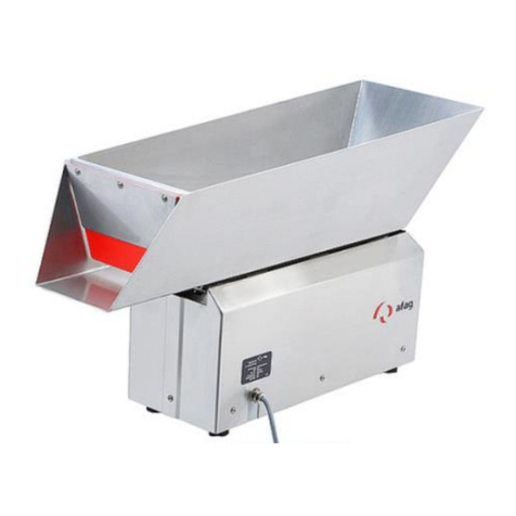
Afag IBB3.5 User manual

Conveyor Belt Hopper
IBB3.5 / IBB6 / IBB12 /
IBB25 / IBB50
Operating and Installation Instructions
Copyright by Afag GmbH

Page 2 2/20/2019 R01.0
This operating instructions are valid for:
Type
Product Code
Conveyor belt hopper IBB3.5
24 V DC
50494738
Conveyor belt hopper IBB6
24 V DC
50494739
Conveyor belt hopper IBB12
230V/50Hz
50494740
Conveyor belt hopper IBB25
230V/50Hz
50494741
Conveyor belt hopper IBB50
230V/50Hz
50494742
Conveyor belt hopper IBB3.5 -without-
24 V DC
50503689
Conveyor belt hopper IBB6 -without-
24 V DC
50503690
Conveyor belt hopper IBB12 -without-
230V/50Hz
50503691
Conveyor belt hopper IBB25 -without-
230V/50Hz
50503692
Conveyor belt hopper IBB50 -without-
230V/50Hz
50503693
Hinged spout IBB3.5
…
50503695
Hinged spout IBB6
…
50503696
Hinged spout IBB12
…
50503697
Hinged spout IBB25
…
50503698
Hinged spout IBB50
…
50503699
Version of this documentation: BA_IBB3.5-50_R01.0_EN.docx
Release: R01.0
Date: 2/20/2019

R01.0 2/20/2018 Page 3
Table of Contents:
1Safety Instructions..............................................................................................5
1.1 Explanation of symbols and notes ............................................................................................................5
1.2 Basic safety instructions ...........................................................................................................................6
1.3 Safety Instructions ....................................................................................................................................6
1.3.1 Danger areas ....................................................................................................................................7
1.4 Intended Use.............................................................................................................................................8
1.5 Improper use.............................................................................................................................................9
2Description of the Device .................................................................................10
2.1 General ...................................................................................................................................................10
2.2 Functional description ............................................................................................................................10
2.3 Technical data ........................................................................................................................................10
2.3.1 IBB3.5 –IBB6..................................................................................................................................10
2.3.2 IBB12 - IBB50..................................................................................................................................11
3Installation Instructions....................................................................................12
3.1 Transport ................................................................................................................................................13
3.2 Unit assembly .........................................................................................................................................13
3.2.1 Notes on safe installation ..............................................................................................................13
3.2.2 Electrical connection......................................................................................................................13
3.3 Power supply ..........................................................................................................................................14
4Operating Instructions...................................................................................... 15
4.1 Commissioning........................................................................................................................................15
4.1.1 Checking the belt run:....................................................................................................................15
4.1.2 Checking the lateral guides............................................................................................................15
4.2 Filling the system ....................................................................................................................................15
4.3 Adjustment options ................................................................................................................................15
4.3.1 Lateral guides.................................................................................................................................15
4.3.2 Parts chute .....................................................................................................................................15
4.3.3 Adjustable front panel ...................................................................................................................15
4.3.4 Belt tensioning ...............................................................................................................................15
5Maintenance Instructions .................................................................................17
5.1 Cleaning ..................................................................................................................................................17
5.2 Conveyor belt..........................................................................................................................................17
5.2.1 Replacing the conveyor belt ..........................................................................................................17
5.3 Drive........................................................................................................................................................19
5.4 Other components ..................................................................................................................................19
5.5 Spare parts..............................................................................................................................................19
6Accessories .......................................................................................................20
Page 4 2/20/2019 R01.0
6.1 Attachment parts....................................................................................................................................20
6.2 Control device .........................................................................................................................................20
6.3 Ordering addresses.................................................................................................................................20
7Disposal ............................................................................................................. 21

R01.0 2/20/2018 Page 5
1Safety Instructions
1.1 Explanation of symbols and notes
Symbols: Installation and commissioning must be performed exclusively by
qualified personal according to the operating instructions.
Please observe the following explanation of symbols and notices. They are categorized
according to danger levels and in according to ISO 3864-2.
DANGER
Identifies an imminent danger.
If the information is not followed, death or severe injuries (physical
disability) may be the result.
WARNING
Identifies a potentially dangerous situation.
If the information is not followed, death or severe injuries (physical
disability) may be the result.
CAUTION
Identifies a potentially dangerous situation.
If the information is not followed, property damage and minor or
moderate bodily injury may be the result.
NOTE
Identifies general information, useful user tips and work recom-
mendations that have an influence on the safety and health of the
personnel.

Page 6 2/20/2019 R01.0
1.2 Basic safety instructions
This operating manual serves as a basis for safe use and operation of the IBB Conveyor
belt hopper. The safety instructions in this manual must be observed in particular by all
persons working on or with the IBB. In addition, the rules and regulations for accident
prevention for the respective place of use must be observed. The operating manual
must always be available in the place of use of the IBB.
Operation of the device must be performed exclusively by technically qualified person-
nel.
Qualified personnel are persons who, on the basis of their training, experience and in-
struction, as well as their knowledge of applicable standards, provisions, accident pre-
vention regulations and operating conditions, have been authorized by the person re-
sponsible for the system of the equipment to perform the respective tasks as required,
and are capable of recognizing and avoiding the potential dangers in the process (defi-
nition for specialized personnel according to IEC 364).
The operating company must regulate precisely the personnel’s areas of responsibility,
competence, and monitoring precisely. If the personnel does not have the necessary
skills, they must be trained and instructed (qualification obligation). If necessary, this
can be provided by the manufacturer on behalf of the operating company. Moreover,
the operating company must ensure that its personnel fully understands the content of
the operating manual.
The following information is provided for personal safety of the operating personnel,
safety of the described products and the connected equipment:
WARNING
Maintenance measures must only be performed by personnel with
the specific certified skills. Here, depending on the scope and de-
gree of difficulty of the assigned maintenance measures, the re-
quired qualifications of the person assigned with the measures can
vary.
1.3 Safety Instructions
Our belt hoppers have been constructed according to state-of-the-art technology and
recognized safety regulations. This operating manual contains basic instructions that
guarantee a fault-free and safe operation. This is why it must definitely be read by the
responsible staff/operator and must always be available in the belt hoppers’ place of
use.
The instructions and labels attached to the belt hopper must be kept in legible condition
and must not be removed! After replacing the wiring, lines and components, all available
marking labels attached to these components must be reinstalled accordingly.
The information relating to work safety relate to the currently applicable directives issued
by the European Union. Also observe the accident prevention regulations for continuous
handling equipment and electrical resources. In other countries, the relevant national
laws and regulations must also be observed and adhered to:
Training employees about hazards and the required safety measures must be repeated
at regular intervals –but at least once a year.

R01.0 2/20/2018 Page 7
Work instructions must be prepared by the operating company of the belt hopper on
how to handle the product parts. This manual, in addition to the operating instructions,
must be completely followed by the operator of the belt hopper. In the interest of occu-
pational health and safety (such as handling cleaning agents), operating instructions
are required which the operating company must prepare.
Commissioning, maintenance and repair work must only be performed by skilled per-
sonnel.
Only such persons must be allowed to work with the belt hopper who have been in-
structed on handling this belt hopper.
Before commissioning the belt hopper, it must be inspected to ensure its settings are
correct and that the required well-functioning safety devices are installed.
The trained and qualified personnel must check the functional state of the protection
and safety devices at the beginning of each shift. If any defects are detected that ad-
versely impact the safety of the belt hopper, then the hopper must be shut down until
these defects have been remedied.
No cleaning tasks may be performed on the belt hopper after it has been switched on.
The operating personnel is not permitted to perform work on the electrical equipment.
Do not reach into the conveyor belts or touch the conveyed goods while the belt hopper
is in operation.
Defective machine parts must be replaced as soon as possible.
As a general rule, no safety devices must be removed or bypassed.
WARNING
Disconnect the belt hopper from the power supply during setup,
maintenance, when making repairs or eliminating faults. Work on
the electrical equipment must only be carried out by a qualified
electrician. There is a risk of injury and danger of electric shock.
Make sure that the protective ground of the power supply is in
properly working condition.
1.3.1 Danger areas
CAUTION
Despite the low conveyor speed, the operating personnel may be
at risk of body parts being caught in the machinery at the positions
listed below due to its use or handling:
a) Area of the fastening rail - conveyor belt
b) Narrow space between hinged spout - conveyor belt (under-
side of hopper)

Page 8 2/20/2019 R01.0
c) Narrow space between trough - conveyor belt (underside of
hopper)
Figure 1: Danger areas IBB
Measures to avoid the aforementioned dangers:
NOTE
▪Disconnect from the power supply before assembly or disas-
sembly work, to switch out a fuse or when making any struc-
tural modifications.
▪Do not perform tasks at the aforementioned narrow spaces (a,
b, c) while the power supply is connected or during operation.
If there is any risk to the operating personnel as a result of equip-
ment use despite these measure, the operating company must en-
sure a suitable cover for the danger areas.
1.4 Intended Use
The intended use of the belt hopper is solely for storing, refilling or transferring specific
product parts. The smallest side length of the product parts must be at least 2 mm.
Product parts any smaller may wedge in below the belt and cause damage or a failure
in the belt hopper.
For standard belts, the product parts must be dry, clean and have no sharp edges.
Special belts must be used for other product parts (oily, wet, hotter than 70°C). Product
parts must not fall onto the conveyor belt from a large height. In case of doubt, ask the
manufacturer. The belt hopper is designed for horizontal transport as max. load. If the
belt hopper is to be operated at a slight incline, ask the manufacturer if it is possible to
do so in your specific case and which utility values need to be observed.
For the permitted conveyor capacity, see chapter 1.4 “Technical data”
Applications:
a
b,c
c

R01.0 2/20/2018 Page 9
- Parts storage for sorting and feeding devices,
- Equipping packaging systems,
- Equipping scales and counting devices,
- Dispensed parts provisioning, at manual workplaces as well,
- Can be used in the food and pharmaceutical industries.
Notes on the functional set-up can be found in chapter 3 “Main Components”
WARNING
After integrating the belt hopper into a complex machine, all re-
quirements as defined in the EC Machinery Directive relating to oc-
cupational health and safety must be met.
Intended use also includes:
- Observing all instructions in the operating manual
- Compliance with the inspection and maintenance tasks.
- Adhering to the general and specific safety instructions in this operating manual as
well as all relevant accident prevention regulations.
In this regard, also refer to the General Terms and Conditions.
1.5 Improper use
Improper use, which may put the belt hopper, the user and third parties at risk, include inter alia:
Use of the belt hopper in any way contrary to its intended use (Chapter 1.3.1), in particular with respect
to:
Equipping the belt hopper with product parts in any form other than specified for the belt hopper. Equip-
ping the belt hopper with parts tainted with oil, grease or any other coating.
Use of unskilled personnel. See chapter 2 “Safety”.
Operating the belt hopper contrary to the specifications provided in the operating instructions with re-
spect to: Safety, transport, installation, use and operation, settings, repairs and maintenance. No safety
and protective devices may be bypassed or put out of service. Work on the belt hopper may only be
performed by professionally skilled and instructed personnel.
Operating the belt hopper if it is defective / has technical defects: such as missing safety devices, prod-
uct parts are defective or damaged.
Operating the belt hopper if there are organizational deficiencies: for example if inadequate operating
personnel are employed, unsuitable work procedures are being applied.
Repairs, cleaning or maintenance work without first securing or switching off the belt hopper.
WARNING
NOTE
Any further use or structural modification is deemed improper and
renders the warranty void.

Page 10 2/20/2019 R01.0
No modifications, additions or conversions may be made to the de-
vice without the consent of the manufacturer.
For this belt hopper, only use parts and resources approved by the
manufacturer as spare parts and auxiliary resources.
The manufacturer shall not be held liable or any damage resulting
from improper use.
There is a risk of accidents, injuries and property damage if the belt
hopper is not used as intended. For this reasons, improper use is
not permitted.
2Description of the Device
2.1 General
The intended use of the belt hopper is solely for storing, refilling or transferring specific
product parts.
Applications:
- Parts storage for sorting and feeding devices,
- Equipping packaging systems,
- Equipping scales and counting devices,
- Dispensed parts provisioning, at manual workplaces as well,
- Can be used in the food and pharmaceutical industries.
2.2 Functional description
The basic element of the IBB Conveyor belt hopper is the conveyor belt, which trans-
ports the parts that are on it to an inclined chute. A specific parts storage container is
attached onto the conveyor belt for the purpose of achieving a certain load volume.
The conveyor belts is driven by a DC gear motor for all sizes, whereas a three-phase
motor is available as an option. Because the DC gear motor has a preferred rotational
direction, any reversing operation of the conveyor belt by reversing the polarity of the
drive voltage will be detrimental to the motor’s service life. However, if the belt hopper
is used as intended, a reversing operation of this kind will not be necessary.
2.3 Technical data
2.3.1 IBB3.5 –IBB6

R01.0 2/20/2018 Page 11
Type
IBB3.5
IBB6
Dimensions
Unit
A
[mm]
377
457
B
[mm]
292
357
C
[mm]
302
362
D
[mm]
150
180
E
[mm]
70
90
F
[mm]
146
166
G
[mm]
177
197
H
[mm]
117
137
K
[mm]
40
40
L
[mm]
160
160
M
[mm]
92.5
92.5
N
[mm]
80
80
Technical data
Unit
Fill weight
[kg]
30
35
Fill volume
[l]
3,5
6
Rated voltage
[V]
24
24
Current consumption
[A]
0.4
0.4
Motor output
[W]
10
10
Operating temperature
[°C]
-5 to
60
-5 to
60
Belt speed
[m/min]
0.1
0.1
2.3.2 IBB12 - IBB50

Page 12 2/20/2019 R01.0
Type
IBB12
IBB25
IBB50
Dimensions
Unit
A
[mm]
552
662
787
B
[mm]
427
547
662
C
[mm]
413
513
613
D
[mm]
230
280
350
E
[mm]
110
120
150
F
[mm]
196
206
246
G
[mm]
232
297
263
H
[mm]
346.5
411.5
476.5
K
[mm]
172
182
207
L
[mm]
256
256
256
M
[mm]
31
31
31
N
[mm]
49
49
49
Technical data
Unit
Fill weight
[kg]
50
60
70
Fill volume
[l]
12
25
50
Power supply (mains voltage/mains
frequency)
[V/Hz]
230/50
230/50
230/50
Current consumption
[A]
0.85
0.85
0.85
Motor output
[W]
90
90
90
Operating temperature
[°C]
-5 to 60
-5 to 60
-5 to 60
Belt speed
[m/min]
0.85
0.85
0.85
3Installation Instructions

R01.0 2/20/2018 Page 13
3.1 Transport
The Conveyor belt hopper is transported packaged on a pallet. The center of gravity is
in the center of the Conveyor belt hopper. Transport the pallet using a stable transport
trolley. The unit’s weight depends on the design of the Conveyor belt hopper and can
be found in the transport documents.
3.2 Unit assembly
3.2.1 Notes on safe installation
Prior to configuring the belt conveyor, make sure that no unauthorized person can start
it up. Attach information signs so that they are clearly visible before starting any work!
Only use tools in good working condition for the work, in particular wrenches that fit and
are not stretched out. Do not work with greasy hands. Slipping accidents!
Make sure that disassembled protective devices are reattached before the initial re-
commissioning.
Trial run: Check to ensure that any used tools, screws, aids or other objects have been
removed from the operational area of the belt hopper.
During setup, make sure that there is no obstruction to the belt run.
3.2.2 Electrical connection
The electrical connectionmust bedone bya qualified electrician only and in accordance
with the enclosed circuit diagram. All connections for the motor, control board, etc. have
been connected to a terminal at the factory, and the unit is already grounded as well. A
screw connection is located on the front of the housing for conducting wires into the
motor housing. Ensure that the supply line diameter is sufficiently sized. The connection
cable must have a properly connected protective conductor. The goal is to not have the
belt hopper run continuously, but to instead to have the belt hopper switched on and off
with a delay by monitoring a minimum/maximum load on the conveyor unit being filled.
Adhere to the circuit diagram on the inside of the motor housing cover. Only authorized
personnel may be allowed to connect the unit.
NOTE
NOTE
Disconnect the Conveyor belt hopper from the power supply prior
to transport.

Page 14 2/20/2019 R01.0
▪Disconnect from the power supply before assembly or dis-
assembly work, to switch out a fuse or when making any
structural modifications.
▪Observe the accident prevention and safety regulations ap-
plicable in the specific usage case.
▪Prior to commissioning, it must be checked whether the
rated voltage of the unit matches the local mains supply.
▪EMERGENCY STOP devices must remain effective in all op-
erating modes. Unlocking the EMERGENCY STOP devices
must not allow the unit to restart uncontrolled.
▪The electrical connections must be covered!
▪Protective conductor connections must be tested for fault-
free function after assembly!
▪Only allow authorized personnel to connect the unit.
3.3 Power supply
The 24V drive unit = must only be operated with 24 volt DC current. Ensure the correct
polarity of the connections. Also ensure that the ground conductor is attached.
The 230 V drive unit must only be operated with 230 V AC current.
WARNING
Disconnect the device from the power source in the event of faults.

R01.0 2/20/2018 Page 15
4Operating Instructions
4.1 Commissioning
Verify that the unit has been properly installed according the chapter 3.2.1 “Notes on
safe installation”
The belt hopper does not have its own control unit and must therefore be controlled by
the unit that the belt hopper is integrated in.
4.1.1 Checking the belt run:
Check the belt run during initial commissioning to ensure it runs centered and readjust
it if necessary. (See chapter 5.2.1 i), “Replacing the transport belt”)
4.1.2 Checking the lateral guides
The lateral guides of the hopper trough must be set to ensure there is no gap between
the hopper belt and the lateral guides. They may need to be readjusted.
4.2 Filling the system
With respect to the maximum filling volume and the maximum filling weight. The per-
missible limit values of your belt hopper can be found in chapter 2.3 “Technical data”.
4.3 Adjustment options
4.3.1 Lateral guides
On both side of the parts storage container are adjustable V2A bars. These bars prevent
transported parts from being wedged under the belt and can be adjusted by loosening
the cap nuts. The feed plates must not obstruct the belt run.
4.3.2 Parts chute
The incline of the chute can be adjusted by loosening the round-head screws. If the
chute is used to feed parts to vibration conveyors, make sure that the parts falling from
the chute do not drop onto any baffles as this can have an adverse effect on the equip-
ment's operation. The parts should be fed into roughly the center of the unit.
4.3.3 Adjustable front panel
There is an adjustable front panel at the conveyor belt’s outlet. The optimum replenish-
ing of the parts depends on the passage height between the top edge of the transport
belt and the lower edge of the front panel. By loosening the two wing screws on the front
panel, the stainless steel pusher can be moved up or down, which will adjust the pas-
sage height to the parts.
4.3.4 Belt tensioning

Page 16 2/20/2019 R01.0
The belt tension and center run on the drive and guide roller has been pre-set at the
factory.
The belt tension must be set so that even if the parts storage container is full (observe
the max. belt capacity of your belt hopper type!) the conveyor belt does not have a gap.
The belt tension is adjusted by turning the round-head screws on the tensioning revers-
ing heads. Rotating in clockwise direction increases the belt tension. At the same time,
this adjustment can also influence the center run of the belt. The conveyor belt must run
centered between the head pieces. If the belt abuts too much on one of the head pieces,
the center run must becorrected to prevent increased wear to the belt. To do so, tighten
the round-head screw on the tensioning reversing head that the belt runs on or loosen
the screw on the opposite tensioning reversing head. Observe the belt tension in the
process!
CAUTION
Tightening the belt too much may overload the belt, the bearings
and also the motor. After making fine adjustments, check the mo-
tor’s current consumption. If it exceeds the rated data on the name-
plate, the round-head screws must be evenly loosened. After mak-
ing the adjustment, perform a test run for several hours. After initial
commissioning, check several times a day to ensure that the belt
is running centered.
Clamping screws on clamping reversing head

R01.0 2/20/2018 Page 17
5Maintenance Instructions
5.1 Cleaning
If necessary, clean the conveyor belt and both tensioning reversing heads with alcohol
and a clean lint-free rag. For food industry operations, use an approved alcohol replace-
ment.
5.2 Conveyor belt
After a two-week run-in period, check the tension and the centering of the conveyor belt
and correct it as necessary. Conduct subsequent inspections in 4-week intervals.
5.2.1 Replacing the conveyor belt
a) Remove the hopper trough and the parts chute (highlighted in green - see image)
b) Remove the fastening struts (highlighted in green - see image)
c) Loosen and remove the clamping screws on clamping reversing head (high-
lighted in green - see image)
Parts chute
Fastening strut
Hopper trough

Page 18 2/20/2019 R01.0
d) Push the belt on the bottom of the conveyor body to the side and loosen the
setscrews on one side of the crosspiece (highlighted in green - see image)
e) Pull both the longitudinal strut and the reversing heads down together (high-
lighted in green - see image)
f) Pull down the conveyor belt (highlighted in green - see image)
g) Remove the fastening struts (highlighted in green - see image)
h) Push a new belt onto the conveyor belt body and reassemble the belt hopper in
revered order.
Setscrews
Clamping screws
Longitudinal strut
Conveyor belt

R01.0 2/20/2018 Page 19
i) Checklist for assembly and settings:
-Make sure both longitudinal struts are at a right angle
-Distortions while tightening the setscrews (crosspiece - see point d)
-Tighten the conveyor belt evenly and ensure it runs centered
-Do not “over-tighten” the belt
-Check the setting of the feed plates and re-adjust if necessary.
-Make sure that the conveyor belt does not grind against the hopper trough.
5.3 Drive
After 2000 operating hours, the carbon brushes must be replaced on the DC motor (if
the unit has them) and the surrounding area must be thoroughly cleaned. Otherwise,
gear motors are maintenance-free for 10,000 operating hours. If necessary, remove
dust around the entire motor area to ensure optimum cooling.
5.4 Other components
None of the other components of the belt hopper require maintenance.
5.5 Spare parts
Spare parts are available upon request.

Page 20 2/20/2019 R01.0
6Accessories
6.1 Attachment parts
At this time, we do not offer any special peripherals for the IBB series belt hoppers.
However, you can find a large assortment of accessories for our range of products in
our Feeding Technology Components Catalog.
6.2 Control device
Type
Power supply
Product code
Remark
IRG1-MS
230V/50Hz
50391018
Sensor-actuation with a timer function
Third-party control devices can also be used, provided they meet the technical specifi-
cations.
6.3 Ordering addresses
Germany:
Afag GmbH
Wernher-von-Braun-Strasse 1
92224 Amberg, Germany
Phone: +49 (0) 96 21 / 65 0 27-0
Fax: +49 (0) 96 21 / 65 0 27-490
Sales
www.afag.com
Switzerland:
Afag Automation AG
Feeding technology
Fiechtenstrasse 32
4950 Huttwil, Switzerland
Phone: +41 (0) 62 / 959 86 86
Fax: +41 (0) 62 / 959 87 87
Other manuals for IBB3.5
1
This manual suits for next models
13
Table of contents
Other Afag Industrial Equipment manuals

Afag
Afag NVB07/0.5 Product guide

Afag
Afag CS 25 Series Manual

Afag
Afag UG 20 Series User manual

Afag
Afag WV151-1 Product guide

Afag
Afag CS 6/20-ED User manual

Afag
Afag CR 20-ZA Quick reference guide

Afag
Afag aflex150 qc User manual

Afag
Afag SA-1 Series User manual

Afag
Afag RA-40-2F Series User manual

Afag
Afag SE20 User manual