Afag LF9 User manual

Linear feeder
LF9 / LF11
Translation of operating and installation instructions
Copyright by Afag GmbH

Page 2 12/02/2020 R05.1
This operation instruction applies to:
Type
Order number
Linear feeder
LF9
230 V / 50 Hz
15105783
115 V / 60 Hz
15068632
Linear feeder
LF11
230 V / 50 Hz
11005757
Version of Documentation: BA_LF9-11_R05.1_EN.docx
Release: R05.1
Date: 12/02/2020

R05.1 12/02/2020 Page 3
Table of contents
1Safety instructions ................................................................................................. 4
1.1 Explanation of symbols and notes ............................................................................................................ 4
1.2 Basic safety information ........................................................................................................................... 5
1.3 Intended use ............................................................................................................................................. 5
1.4 Notes for Pacemakers and Defibrillators .................................................................................................. 5
2Description of the LF linear feeder........................................................................ 6
2.1 General ..................................................................................................................................................... 6
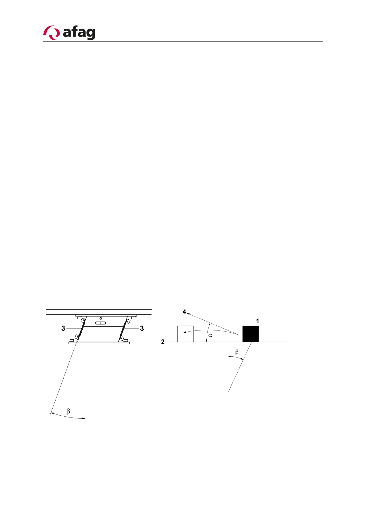
2.2 Functional description............................................................................................................................... 6
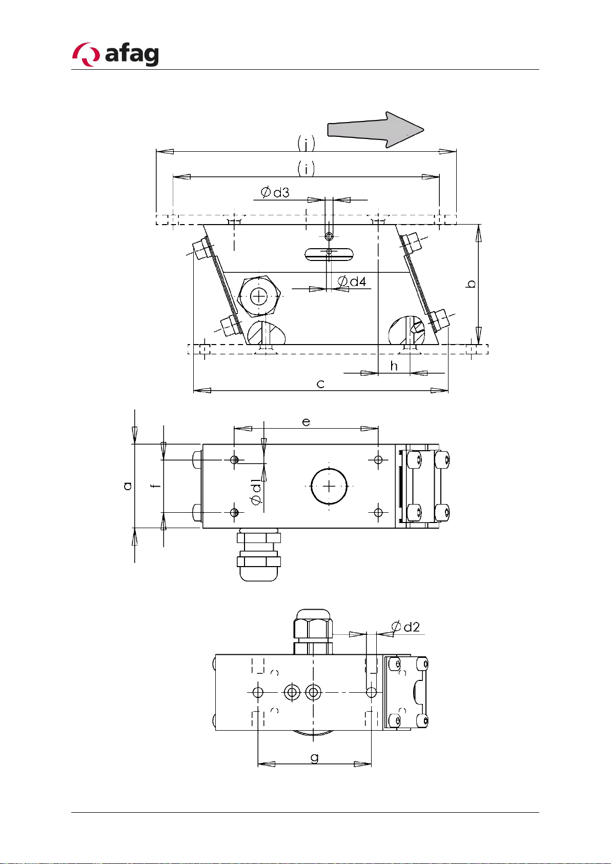
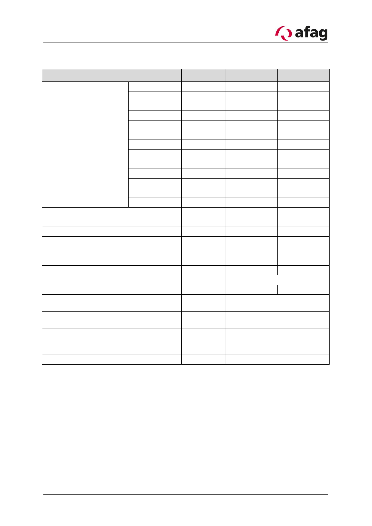
2.3 Technical data........................................................................................................................................... 8
3Assembly instructions......................................................................................... 10
3.1 Transport ................................................................................................................................................ 10
3.2 Installing the unit.................................................................................................................................... 10
3.3 Mounting of the linear track................................................................................................................... 11
3.4 Power supply........................................................................................................................................... 12
4Operating instructions......................................................................................... 13
4.1 Correlations between the transport speed and the LF spring package .................................................. 13
4.2 Setting the distance between the rail and the support surface .............................................................. 14
4.3 Standard operation................................................................................................................................. 14
4.4 Torques ................................................................................................................................................... 15
5Maintenance instructions .................................................................................... 16
5.1 Troubleshooting and fault repair ............................................................................................................ 16
5.2Replacing springs or spring packages ..................................................................................................... 18
5.3 Replacing the magnetic coil.................................................................................................................... 20
5.4 Setting the air gap between magnetic coil and anchor bolt................................................................... 22
5.5 Spare and wearing parts......................................................................................................................... 23
6Accessories .......................................................................................................... 24
6.1 Mounting parts ....................................................................................................................................... 24
6.2 Control device ......................................................................................................................................... 24
6.3 Address for orders................................................................................................................................... 25
7Disposal ................................................................................................................ 25

Page 4 12/02/2020 R05.1
1Safety instructions
1.1 Explanation of symbols and notes
Symbols: Assembly and commissioning must be carried out by qualified person-
nel only and according to these operating instructions.
Please observe the meaning of the following symbols and notes. They are grouped into
risk levels and classified according to ISO 3864-2.
DANGER
Indicates an immediate threatening danger.
Non-compliance with this information can result in death or seri-
ous personal injuries (invalidity).
WARNING
Indicates a possible dangerous situation.
Non-compliance with this information can result in death or seri-
ous personal injuries (invalidity).
CAUTION
Indicates a possibly dangerous situation.
Non-compliance with this information can result in damage to
property or light to medium personal injuries.
NOTE
Indicates general notes, useful operator tips and operating rec-
ommendations which don’t affect safety and health of the person-
nel.

R05.1 12/02/2020 Page 5
1.2 Basic safety information
This operating manual provides the basis for the safe use and operation of the linear
feeder. This operating manual and, in particular, the included safety instructions have to
be observed by all individuals working with and on the linear feeder. In addition, all rules
and regulations regarding the accident prevention applicable for the site of operation are
to be complied with.
The operating manual must always be kept at the site of operation of the linear feeder.
1.3 Intended use
The linear feeder is intended to convey component parts of different sizes, designs and
types of material.
The workpieces must meet the following requirements in order to ensure a problem-free
operation:
-they must be free of oil, grease and burrs
-they must not be sticky
-they must not be statically charged
-they must not be magnetic (no self-magnetism)
-they must be free of dirt and not be mixed with foreign parts
-rubber parts can be powdered with talcum
1.4 Notes for Pacemakers and Defibrillators
Afag vibration conveyors are tested in accordance with regulation 15 of the German Statuto-
ry Accident Insurance Association [Deutsche Gesetzliche Unfallversicherung, DGUV] (previ-
ously BGV B11 of German Accident Prevention Regulations). The permissible values of ex-
posure area 2 are not exceeded, therefore no measures are required pursuant to Section 4
(2) of the DGUV regulation 15. The definitions of Section 12 “Indirect Effects, Medical Im-
plants” remain unaffected by the above.
The alternating magnetic fields that occur in the immediate vicinity of certain vibration con-
veyors may affect the proper functions of active implants, i.e. pacemakers and defibrillators.
Anyone with active medical implants, for which no individual risk assessment has been pro-
vided, must observe the specified safety distances to the vibration conveyors. The distances
each relate to the position of the upper body and the active medical implant relative to the
field source.
Type
Safety Distance
LF9 / LF11
5cm

Page 6 12/02/2020 R05.1
2Description of the LF linear feeder
2.1 General
The LF, together with a transport rail, is designed for feeding bulk materials.
The LF must only be used in combination with the corresponding Afag controller. This
combination guarantees optimum transport behaviour.
The LF must be fixed onto a sufficiently solid support, in order to avoid the conduction of
vibrations to other parts
2.2 Functional description
The LF is a unit which transforms electromagnetic oscillations in order to use them to
feed component.
The basic construction of the LF contains the following elements:
(see Figure 1)
1 Material to be conveyed
2 Feeder rail
3 Leaf springs
4 Jumping-off direction
αJumping-off angle
βInclination of leaf spring
Figure 1

R05.1 12/02/2020 Page 7
The magnet, connected to the support, creates a force which attracts reps. releases the
oscillating plate dependent on the oscillation frequency of the power supply.
The pulsating movement of the oscillation plate causes the material to jump from the rail
at each oscillation and is conveyed as a result of the angle of inclination of the leaf
springs.
On a cycle of the 50Hz alternating current supply, the magnet achieves twice its maxi-
mum pulling force while this is independent of the direction of current flow. The magnet
thereby produces an oscillating frequency of 100 Hz. This 100 Hz oscillation is necessary
to achieve a smooth or gentle transport.
With heavy or large work pieces however, it is necessary to use an oscillating frequency
of 50 Hz. A half wave of the mains supply is thereby blocked.

Page 8 12/02/2020 R05.1
2.3 Technical data
Figure 2 Dimensions LF
Figure 3 Dimensions LF
Conveying direction

R05.1 12/02/2020 Page 9
Table 1: Technical data
Description
Units
LF11
LF9
Dimensions
a
[mm]
35
32
b
[mm]
50
39
c
[mm]
106,15
89
d1
-
M4
M4
d2
-
-
M5
d3
[mm]
3,3
-
d4
[mm]
2,1
-
e
[mm]
60
54
f
[mm]
22
16
g
[mm]
-
48
h
[mm]
13,2
7
(i)
[mm]
115
88
(j)
[mm]
125
100
Operating voltage
[VAC]
230
230 / 115
Mains frequency
[Hz]
50
50 / 60
Degree of protection
[IP]
54
40
Vibration frequency (full wave)
[1/min]
6000
6000 / 7200
Vibration frequency (half wave)
[1/min]
3000
-
Weight (LF only)
[kg]
0,95
0,75
Spring thickness (standard)
[mm]
0,5
0,7
Air gap (Magnetic coil-anchor bolt)
[mm]
0,2-0,4
Magnet performance
[VA]
46
18
Environmental conditions for operation:
Temperature range
[°C]
-10 to +45
Noise emission: Continuous noise pres-
sure level (without transported material)
[dB]
<70
Measuring height/measuring distance
[m]
1,6 / 1
Measurement direction with respect to the
noise source
[°]
90
Measurement method
-
A evaluation

Page 10 12/02/2020 R05.1
3Assembly instructions
3.1 Transport
WARNING
Improper use of transport means (industrial trucks, cranes, tech-
nical aids, sling gear etc.) may lead to bruises and other injuries.
Required behaviour:
-Observe and follow the transport and maintenance instruc-
tions
-Proper use of transport means
CAUTION
When transporting the LF, it must be held and lifted at the support
only.
The transport rail is not to be held.
3.2 Installing the unit
The LF is firmly screwed to the foundation using the boreholes on the bottom. 2 screws
in case of the LF9 are affixed from below. The use of mounting plates allows the optional
mounting from above. (See Chapter 6.1 Mounting parts).
Figure 4

R05.1 12/02/2020 Page 11
For the operation, the linear feeder must always be mounted on a sufficiently dimen-
sioned (mass) subframe. The subsurface should be vibration-resistant (plate or block
design) in order to absorb the vibration forces.
Self-supporting profiles must be reinforced by a base plate on which the linear feeder is
attached. A steel plate should be used which is at least 20mm thick and more than
120mm wide.
Suitable substructures are to be provided for the height adjustment. Suitable afag stand-
ard parts are available for complete station extensions in combination with afag helical
conveyors.
During the assembly of the linear feeder make sure that the base is horizontal or slightly
inclined in the direction of transport (1.5-2°).
3.3 Mounting of the linear track
In order to achieve optimum transport speed, the following basic requirements must be
fulfilled:
1. The rail and LF-support must match each other
2. The structure of the rail must transmit the vibration ideally. (rail-profile standing,
not flat)
3. The length of the conveyor rail must not exceed the maximum permissible length.
(see 2.3 Technical data)
4. Depending on the material to be conveyed, a maximum of two additional support
springs is necessary.
5. The weight of the rail (including parts) must not exceed the weight limit. (see 2.3
Technical data)
The rail is to be aligned approximately symmetrical to the intermediate plate of the linear
feeder. The conveying speed can be increased by tilting the rail in the direction of travel
by 1.5 –2°.
All LF models feature four boreholes on the upper side of the drive to connect the con-
veying rail to the vibratory conveyor. (See Chapter 2.3 Technical data)

Page 12 12/02/2020 R05.1
3.4 Power supply
WARNING
▪Any work on the electrical supply may only be performed
by trained, authorised, qualified personnel.
▪The power supply must be protected by an FI switch (pro-
vided by the customer).
▪The helical conveyor may only be operated with the power
supply specified on the name plate.
The IRG1-S device can be used to activate the linear feeder. The MSG801 or MSG802
can also be used. Please note that an additional CEE connector plug is required for the
MSG controllers (Order number: 11006982)
Installation of the plug is only to be carried out by technically qualified personnel accord-
ing Figure 5.
Figure 5: End of the wire for additional plug

R05.1 12/02/2020 Page 13
4Operating instructions
4.1 Correlations between the transport speed and the LF spring package
(See Figure 6)
Basically the LF and the transport rail are adjusted in the standard configuration. This
means that all oscillating elements are set optimally.
The following factors however influence the combination LF / transport rail:
-The parts to be conveyed (size, weight, shape, material and quality)
-The feed rate
-The support
-Surrounding (are there other oscillating components with disturbing influence or
shakes from handling components)
Procedure for adjustment of the oscillating system:
WARNING
Unplug the power cable, before proceeding with further actions!
1. Check the settings on the control device (see separate operating manual).
2. Check that all springs and fixing screws are tight
3. Check that the type and frequency of the magnets is correct (see chapter 2.3)
4. Check the air gap between magnetic coil and the anchor bolt (see chapter 5.4)
5. Switch on the LF and alter the transport speed with the controller regulator.
6. Depending on the transport material, additional springs have to be installed or
removed (see Chapter 5.2).

Page 14 12/02/2020 R05.1
4.2 Setting the distance between the rail and the support surface
This setting is only necessary when:
-All spring packages have been exchanged or re-assembled
-The LF has been dismantled
WARNING
Unplug the power cable, before proceeding with further actions!
1. Loosen the screws slightly (1)
2. The distance Xin front and at the back of the linear feeder has to be the same.
Check the dimension of X
3. Tighten the spring package screws again (1)
4. Check the air gap between the magnetic coil and the anchor bolt and adjust if
necessary (see chapter 5.4)
Figure 6
4.3 Standard operation
No further settings are required for standard operation mode once the controller is
switched on.

R05.1 12/02/2020 Page 15
4.4 Torques
Tightening torques MSp in Nm for shank screws with metric ISO control threads and head
supports according to DIN 912 or DIN 931:
Tightening torques MSp in Nm
Screw
Strength class 8.8
Strength class 10.9
Strength class 12.9
M4
2,8
4,1
4,8
M5
5,5
8,1
9,5
M6
9,5
14,0
16,5
(M7)
15,5
23,0
27,0
M8
23,0
34,0
40,0
M10
46,0
68,0
79,0
M12
79,0
117,0
135,0
M14
125,0
185,0
215,0
M16
195,0
280,0
330,0
M18
280,0
390,0
460,0
M20
390,0
560,0
650,0
M22
530,0
750,0
880,0
M24
670,0
960,0
1120,0
M27
1000,0
1400,0
1650,0
M30
1350,0
1900,0
2250,0
by: Dubbel (18th edition), page G175

Page 16 12/02/2020 R05.1
5Maintenance instructions
WARNING
The electrical equipment of the linear feeder must be checked at
regular intervals. Loose connections, burnt or damaged cables
are to be removed immediately!
NOTE
Check all visible screws for tightened
5.1 Troubleshooting and fault repair
WARNING
Electrical work must only be carried out by trained personnel!
WARNING
Unplug the power cable, before proceeding with further actions!
Interruptions caused by defective components must be repaired by replacing the defec-
tive component, only.
NOTE
Defective components must only be replaced by Afag original
spare parts.

R05.1 12/02/2020 Page 17
Linear feeder does not run after switching it on
Cause of fault:
Fault repair
Plug not connected
Connect plug
Connecting cable between bowl feeder
and controller not plugged in
Connect plug
Regulator on controller set to „0“
Turn regulator to position
Defective fuse in control unit
Replace fuse
Bowl feeder lacks performance after operating for a certain length of time
Cause of fault:
Fault repair
The spring package fixing screws have
become loose
Remove the casing and retighten all spring
package screws
The air gap between the magnetic coil
and the anchor bolt is no longer correct
Remove the casing and readjust the air
gap (See chapter 5.4)
Spring broken
Remove the casing and replace the broken
spring (See chapter 5.2)
Regulator on control unit has moved
Readjust regulator
Bowl feeder develops loud noises
Cause of fault:
Fault repair
The magnetic coil or anchor bolt have
become loose
Tighten the screws (See chapter 5.3)
Transport-speed incorrect
Cause of fault:
Fault repair
Potentiometer defective
Replace potentiometer (See „Controller
operating instructions“)

Page 18 12/02/2020 R05.1
5.2 Replacing springs or spring packages
(See Figure 7)
This procedure is only necessary when:
-The oscillating behaviour of the LF has changed
-A spring is broken
WARNING
Unplug the power cable, before proceeding with further actions!
NOTE
Spring packages must contain the same leaf spring type!
The relevant spring cross section can be taken from chapter 2.3.
1. Loosen the screws (1) on the oscillation plate (2), as well as the support (3) and
remove them, together with the spacers (4)
2. Remove the springs (5) and replace with a new package
NOTE
Broken springs have to be replaced with the same spring type and
thickness.
3. Tighten (1) the screws.
4. Establish parallelism between the oscillation plate and the support base (see chap-
ter 4.2)
5. Check the air gap between the magnetic coil and the anchor bolt and adjust if
necessary (see chapter 5.4)
6. Carry out a test run.

R05.1 12/02/2020 Page 19
Figure 7

Page 20 12/02/2020 R05.1
5.3 Replacing the magnetic coil
(see Figure 8)
This procedure is only necessary when:
-The magnetic coil is defective
WARNING
Unplug the power cable, before proceeding with further actions!
1. Loosen the screws (1) on the oscillation plate (2) and remove the entire unit
2. Unplug the Euro plug from the control unit and disassemble
WARNING
Electrical work must only be carried out by trained personnel!
3. Remove the screws (5) from the distance plate (6), if installed and remove the dis-
tance plate from the support base (7) by loosening the screws (8)
4. Loosen the cable clamp (9) and remove the screws (10). Remove the magnetic
coil (11) and pull the cable through the cable clamp.
5. Reassemble in the reverse order.
NOTE
This procedure generally includes adjustment of the air gap be-
tween the magnetic coil and the anchor bolt. (See chapter 5.4).
Other manuals for LF9
1
This manual suits for next models
1
Table of contents
Other Afag Industrial Equipment manuals

Afag
Afag IBB3.5 User manual

Afag
Afag ES40 User manual

Afag
Afag PS 25/50 User manual

Afag
Afag RA-40-2F Series User manual

Afag
Afag DG 16-W Quick reference guide

Afag
Afag BF20 Product guide

Afag
Afag PDZ-128 User manual

Afag
Afag EU-20 User manual

Afag
Afag EPS mini YZ User manual

Afag
Afag GMK 20 Series User manual