AFRISO Eurovac HV User manual

Mess-, Regel- und
Überwachungsgeräte
für Haustechnik,
Industrie und Umweltschutz
Lindenstraße 20
74363 Güglingen
Telefon +49 7135-102-0
Service +49 7135-102-211
Telefax +49 7135-102-147
www.afriso.de
Read instructions before using device!
Observe all safety information!
Keep instructions for future use!
06.2011 0
854.001.0511
Operating Instructions
Leak Detector High Vacuum Type Leckanzeiger
Eurovac HV Z-65.22-4
Eurovac HV # 43750
... in protective housing # 43776
... in protective housing
with heating # 43781

2 Eurovac HV
Contents
1This instruction manual............................................................................................4
1.1 Precautions ..................................................................................................4
1.2 Explanation of symbols and typeface ..........................................................4
2Safety ......................................................................................................................5
2.1 Intended use ................................................................................................5
2.2 Predictable incorrect application..................................................................6
2.3 Safe handling ...............................................................................................6
2.4 Staff qualification..........................................................................................6
2.5 Modifications to the product.........................................................................7
2.6 Usage of spare parts and accessories.........................................................7
2.7 Liability information ......................................................................................7
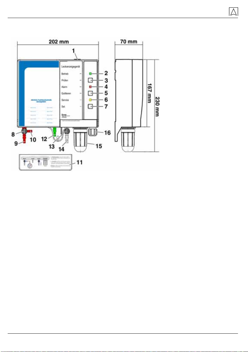
3Product description..................................................................................................8
3.1 Function........................................................................................................9
3.2 Operating modes..........................................................................................9
3.3 Application examples.................................................................................10
4Technical specifications.........................................................................................11
4.1 Approvals, tests and conformities..............................................................12
5Transport and storage...........................................................................................13
6Mounting and commissioning................................................................................13
6.1 Preparing the tank......................................................................................13
6.2 Preparing mounting....................................................................................14
6.3 Installation site ...........................................................................................15
6.4 Installing the leak detector .........................................................................15
6.5 Electrical connection..................................................................................16
6.6 Hose connections.......................................................................................18
6.7 Valve settings.............................................................................................20
6.8 Commissioning the device.........................................................................20
7Operation...............................................................................................................21
7.1 Alarm condition ..........................................................................................21
7.2 Function test...............................................................................................21
8Maintenance..........................................................................................................23
8.1 Service indication.......................................................................................23
8.2 Maintenance activities................................................................................24
9Troubleshooting.....................................................................................................25
9.1 Evaluation of the pump operating time ......................................................26
10 Shutting down, disposal ........................................................................................27
11 Spare parts and accessories.................................................................................27

12 Warranty................................................................................................................28
13 Copyright ...............................................................................................................28
14 Customer satisfaction............................................................................................28
15 Addresses..............................................................................................................28
16 Appendix................................................................................................................29
16.1 Certificate of expert....................................................................................29
16.2 List of substances for Eurovac HV leak detector.......................................30
16.3 Approval documents...................................................................................33
Eurovac HV 3

This instruction manual
1 This instruction manual
This instruction manual is part of the product.
Read this manual before using the product.
Keep this manual during the entire service life of the product
and always have it readily available for reference.
Always hand this manual over to future owners or users of the
product.
1.1 Precautions
WARNING TERM
Type and source of the danger are shown here.
Precautions to take in order to avoid the danger are shown
here.
There are three different levels of warnings:
Warning Term Meaning
DANGER Immediately imminent danger!
Failure to observe the information will result in
death or severe injuries.
WARNING Possibly imminent danger!
Failure to observe the information may result in
death or severe injuries.
CAUTION Dangerous situation!
Failure to observe the information may result in
minor or severe injuries as well as damage to
property.
1.2 Explanation of symbols and typeface
Symbol Meaning
Prerequisite for an activity
Activity consisting of a single step
1. Activity consisting of a several steps
Result of an activity
• Bulleted list
Text Indication on display
Highlighting Highlighting
4 Eurovac HV

Safety
2 Safety
2.1 Intended use
The Eurovac HV leak detector for vacuum systems is a class 1 leak
detector according to EN 13160-1.
The Eurovac HV leak detector may only be used to detect leaks in
tanks which are not pressurised (i.e. operated under atmospheric
conditions) and which are used for aboveground or underground
storage of liquids.
Tanks
• Double-walled steel tanks as per EN 12285-1/-2, DIN 6618-2/-4,
DIN 6619-2, DIN 6623-2, DIN 6624-2
• Steel or plastic tanks, double-walled or single-walled with leak
protection lining or leak protection coating, with approval of use
of the German Institute for Building Technology (Deutschen In-
stitut für Bautechnik) for connection of a vacuum type leak de-
tector
The interstitial spaces of the tanks must be resistant to the liquid and
its vapours and must not contain leak detection fluid.
Liquids
• Water-polluting liquids with a flash point > +55 °C (formerly
danger class AIII), which do not become viscous and which do
not release solid matter
• AdBlue® (urea solution 32.5 %) according to DIN 70070
The leak detector must be resistant to the liquid and its vapours. The
materials used are: PVC, silicone, ABS, NBR, PA6, EPP, EPDM.
Resistance has been proven for the liquids listed in the list of sub-
stances in chapter 16.2, page 30.
The permissible density of the liquid depends on the tank used and
its content.
Tank according to Contents Permissible den-
sity
EN 12285-1/-2, DIN 6619-2,
DIN 6623-2, DIN 6624-2 --- ≤1.9 kg/l
≤100 m³ ≤1.3 kg/l
≤80 m³ ≤1.69 kg/l
DIN 6618-2/-4
≤60 m³ ≤1.9 kg/l
Eurovac HV 5

Safety
Any use other than the application explicitly permitted in this instruc-
tion manual is not permitted.
2.2 Predictable incorrect application
The Eurovac HV leak detector must never be used in the following
cases:
• Hazardous area (Ex)
If the device is operated in hazardous areas, sparks may cause
deflagrations, fires or explosions.
• Use with aggressive liquids which attack the connection hoses
and the leak detector.
2.3 Safe handling
This product represents state-of-the-art technology and is made ac-
cording to the pertinent safety regulations. Each device is subjected
to a function and safety test prior to shipping.
Operate the product only when it is in perfect condition. Always
observe the operating instructions, all pertinent local and na-
tional directives and guidelines as well as the applicable safety
regulations and directives concerning the prevention of acci-
dents.
WARNING
Severe burns or death caused by mains voltage in the control
unit.
Do not expose the leak detector to water.
Interrupt the mains voltage supply before opening the leak de-
tector or before performing maintenance and cleaning work and
make sure it cannot be switched on by accident.
Do not tamper with the leak detector in any way whatsoever.
2.4 Staff qualification
Mounting, commissioning, maintenance and cleaning may only be
performed by specialised companies as per § 3 of the German Ordi-
nance on Installations for Handling Water-Polluting Substances
(VAwS of March 31, 2010) unless such activities do not have to be
performed by specialised companies according to the applicable lo-
cal directives or unless the manufacturer of the device has such ac-
tivities performed by his own, trained staff.
Electrical work may only be performed by trained electricians and in
compliance with all applicable local and national directives.
6 Eurovac HV

Safety
2.5 Modifications to the product
Changes or modifications made to the product by unauthorised per-
sons may lead to malfunctions and are prohibited for safety reasons.
2.6 Usage of spare parts and accessories
Usage of unsuitable spare parts and accessories may cause dam-
age to the product.
Use only genuine spare parts and accessories of the manufac-
turer (refer to chapter 11, page 27).
2.7 Liability information
The manufacturer shall not be liable in any form whatsoever for
direct or consequential damage resulting from failure to observe the
technical instructions, guidelines and recommendations.
The manufacturer or the sales company shall not be liable for costs
or damages incurred by the user or by third parties in the usage or
application of this device, in particular in case of improper use of the
device, misuse or malfunction of the connection, malfunction of the
device or of connected devices. The manufacturer or the sales
company shall not be liable for damage whatsoever resulting from
any use other than the use explicitly permitted in this instruction
manual.
The manufacturer shall not be liable for misprints.
Eurovac HV 7

Product description
3 Product description 1 Rubber grommet
2 Green LED “Suppln
ON”
3 Button “Test”
4 Red LED “Alarm”
5 Button “Mute”
6 Yellow LED “Service”
7 Button “Set”
8 Measurement valve
9 Measurement line
connection
10 Pressure gauge con-
nection
11 Cover for hose con-
nections
12 Exhaust line connec-
tion
13 Test valve
14 Suction line connection
15 Condensate trap with
filter
16 Cable gland
Fig. 1: Exterior view and dimensions
The Eurovac HV leak detector generates a constant vacuum in the
interstitial space of the tank and triggers an alarm if the vacuum
drops.
Eurovac HV contains the following elements in an impact-resistant
plastic housing: display elements and controls, a vacuum pump, a
pressure switch, a printed circuit board with the electronic compo-
nents for processing the output signal, a filter and three hose con-
nections for the pneumatic connection to the interstitial space of the
tank.
The green LED “Supply ON” lights up when mains voltage is avail-
able. The alarm is indicated visually and audibly and is made avail-
able via a voltage-free relay contact (1 changeover contact).
8 Eurovac HV

Product description
3.1 Function
Via the suction line, the vacuum pump installed in the leak detector
generates a vacuum in the interstitial space of the tank. The pres-
sure switch measures the pressure in the interstitial space via the
measurement line and keeps it at a constant level together with the
vacuum pump.
If a leak occurs in the tank's wall or in the leak protection lining (in
the inner or outer wall of the tank) either above or below the level of
the stored liquid or the ground water, and if this leak is greater than
the pump's suction capacity, the vacuum will drop. When the alarm
threshold is reached, the red LED “Alarm” and the audible alarm are
activated and the relay is energised. The audible alarm can be
muted with the button “Mute”.
3.2 Operating modes
Eurovac HV is equipped with an output relay to transmit the alarm
signal to additional external devices. If no error condition is present,
the relay is de-energised. In the case of an alarm, the relay is ener-
gised.
Eurovac HV can be operated with or without additional external de-
vices. The following types of additional devices can be used: visual
and audible alarm units, telecommunication devices, building control
systems, building automation systems, etc.
Eurovac HV 9

Product description
3.3 Application examples 1 Eurovac HV
2 AFRISO event re-
porting system
3 Internet
4 E-mail
5 Cell phone
6 Fax
7 Phone
Fig. 2: AFRISO event reporting system for remote reporting of leaks
1 Red: Measurement line
2 Green: Exhaust line
3 Transparent: Suction
line
4 Electrical connection
5 Condensate trap
6 Tank vent
7 Liquid barrier
8 Outer tank wall
9 Interstitial space
Fig. 3: Application example
10 Eurovac HV

Technical specifications
Fig. 4: Eurovac in protective housing, without (A) or with heating (B),
pre-assembled and ready to be connected. The horn is connected to
the output relay. Protection IP 55.
1 Horn HPW 2 5 Red: Measurement line
2 Mute button for horn HPW 2 6 Green: Exhaust line
3 Eurovac 7 Transparent: Suction line
4 Protective housing 8 Heating controller
9 Heating
4 Technical specifications
Table 1: Technical specifications
Parameter Value
General specifications
Weight 1.1 kg
Emissions The A-evaluated sound level of the au-
dible alarm is at least 70 dB(A) at a dis-
tance of one metre.
Output relay 1 changeover contact
Breaking capacity output
relay Max. 250 V, 2 A, resistive load
Relay fuse T 2 A
Eurovac HV 11

Technical specifications
12 Eurovac HV
Parameter Value
Operating pressure in
interstitial space Approx. -400 mbar
Switch point Alarm On -325 to -355 mbar
Switch point Alarm Off -380 mbar (point of reference, results
from switching hysteresis)
Switch point Pump On -380 mbar (point of reference, results
from switching hysteresis)
Switch point Pump Off -410 to -450 mbar
Connecting hose PVC hose 6 x 2 mm
Temperature range
Ambient -5 °C to +50 °C
Storage -10 °C to +60 °C
Voltage supply
Nominal voltage AC 100-240 V ± 10 %
Rated power < 10 VA
Electrical safety
Degree of protection II
Protection IP 30
Mode of operation and
additional mode of op-
eration
Type 1.B
Electromagnetic compatibility (EMC)
Interference According to CISPR 22
Noise immunity According to EN 61000
4.1 Approvals, tests and conformities
Eurovac HV complies with the EMC Directive (2004/108/EC), the
Low Voltage Directive (2006/95/EC), the Construction Products Di-
rective (89/106/EEC) and has the Technical Approval of the German
Institute for Building Technology Z-65.22-4.

Transport and storage
5 Transport and storage
CAUTION
Damage to the device due to improper transport.
Do not throw or drop the device.
Protect from wetness, humidity, dirt and dust.
CAUTION
Damage to the device due to improper storage.
Protect from wetness, humidity, dirt and dust.
6 Mounting and commissioning
The leak detector may only be installed and commissioned by a spe-
cialised company, see chapter 2.4, page 6.
6.1 Preparing the tank
Tanks whose interstitial space is still (partially) filled with leak
detection fluid
1. You need a collecting container (bucket with a capacity of at
least 10 l), a vacuum pump (min. capacity 1.5 m³/hour) to re-
move the liquid from the interstitial space and a carboy with a
capacity of at least 10 l.
2. Disconnect the connection line of the leak detection fluid con-
tainer from the tank.
3. Collect the escaping leak detection fluid in the bucket.
4. Dismount the test valve, the connection line and the container
for the leak detection fluid with the plug-in probe.
5. Clean the 1" threaded sockets for the leak detection fluid con-
tainer and the test valve and mount/seal suitable adapters and
hose connection pieces so that the suction hose and measure-
ment hose of the Eurovac HV can be connected.
6. Insert two hoses into the carboy neck and seal them (suction
hose pump, suction hose tank). Leave the hose connection for
the measurement line open for the time being so that air can be
admitted.
7. Suck the leak detection fluid from the interstitial space into the
carboy until the liquid column becomes unstable and air is with-
drawn. Remove the maximum possible volume of liquid from the
interstitial space, but at least the following volume:
Eurovac HV 13

Mounting and commissioning
Table 2: Minimum volume to be withdrawn
Tank capacity Minimum volume to be withdrawn
1-5 m³ 5 l
7-13 m³ 10 l
16-30 m³ 15 l
40-60 m³ 30 l
80-100 m³ 35 l
8. Connect vacuum gauges to the measurement connection.
9. Keep withdrawing at a vacuum of -0.5 to -0.8 bar.
10. It is absolutely indispensable for the top area of the tank to con-
tain air. When the pumped volume decreases, interrupt the
pumping process several times so that additional liquid can flow.
If the suction volume becomes too small, alternating withdrawal
via the measurement connection may prove to be more suc-
cessful.
11. Always make sure to withdraw the maximum volume possible,
but at least the volume specified in table 2so that a sufficient air
volume is created above the remaining liquid.
12. Dismount the pumping equipment.
6.2 Preparing mounting
Basic vacuum
The vacuum pump of the leak detector must not exceed the pump
capacity of 100 l/h.
Generate a vacuum of approx. -400 mbar in the interstitial
space. Use an installation pump with a greater capacity for this
purpose.
Leak test
Check for leaks in the interstitial space.
A slight pressure drop in the first hour is unavoidable. After that,
there should be no noticeable pressure loss.
Adaptation
Reduce the vacuum in the interstitial space to -370 mbar.
If the vacuum is greater when the leak detector is connected,
the measuring system may be damaged or destroyed.
14 Eurovac HV

Mounting and commissioning
6.3 Installation site
Choose an installation site that is as close as possible to the
tank to be monitored. The ambient temperature specified must
not be exceeded.
Mount the leak detector to an even, rigid and dry wall at eye
level.
The leak detector must be accessible and easy to oversee at all
times.
The leak detector must not be exposed to water or splash water.
Do not mount the leak detector in damp rooms.
The leak detector must not be installed in hazardous areas or in
access chambers of underground tanks.
If the case of outdoor applications, the leak detector must be
mounted in a protective housing with IP 55 protection. If the leak
detector is installed in a protective housing, an additional
weather-proof audible alarm must be installed outside of the
protective housing. See chapter 11, page 27 for accessories.
If the leak detector is installed below rooftops or in rooms that
are only partially closed, protect it against direct atmospheric in-
fluences or use a protective housing as mentioned above.
6.4 Installing the leak detector
1. Fasten the leak detector the wall (use Aor B),
a drilling template is included.
Eurovac HV 15

Mounting and commissioning
2. Open the leak detector.
3. Connect the unit electrically as described in chapter 6.5 on
page 16.
4. Close the leak detector.
6.5 Electrical connection
Mains voltage is interrupted and cannot be switched on by acci-
dent.
Connect the leak detector directly to the supply network without
a switch and without a plug!
If you want to route the mains or relay cable trough the top of
the housing, replace the rubber grommet at the top of the hous-
ing by the enclosed cable gland.
Close any cable glands at the bottom of the housing that are not
used by means of the enclosed plugs.
16 Eurovac HV

Mounting and commissioning
1 Pressure switch
2 Pump
3 Cable routed through
upper cable gland
4 Cable routed through
bottom cable gland
5 Relay fuse
6
7 Relay connection
Mains connection
Fig. 5: Electrical connection
Power supply
Connect the leak detector to mains by means of a permanently in-
stalled cable such as NYM-J 2 x 1.5 mm².
1. Route the mains cable through the upper or bottom cable gland
into the leak detector.
2. The phase must be connected to terminal L1, the neutral con-
ductor to terminal N. The leak detector supply cable must have
a separate fuse (max. 16 A).
Output
The output signal of the leak detector is made available via a volt-
age-free relay contact (1 changeover contact).
Permanently install the relay cable, route it through the upper or
bottom cable gland into the leak detector and connect it to the
terminals with the corresponding designations.
Safely isolate the relay cable. The isolation characteristics of the
relay cable must at least comply with IEC 60227 or IEC 60245.
If no error condition is present, the relay is de-energised. In the case
of an alarm, the relay is energised.
Eurovac HV 17

Mounting and commissioning
CAUTION
Destruction of the switching contact and adverse effects on the
function of electrical systems due to voltage peaks when induc-
tive consumers are switched off.
Use commercially available standard RC combinations such as
0.1 µF/100 Ohm for inductive consumers.
9 V battery for alarm in the case of power failure
If a standard 9 V battery is connected, an alarm sound is activated in
the case of a power failure. The alarm sound cannot be muted; it re-
mains on until mains power is available again. When mains power is
available again, the device immediately resumes operation. If a leak
has occurred in the meantime, this is indicated.
6.6 Hose connections
Hoses from the leak detector to the tank to be monitored, see also
fig. 3, page 10.
1. Use pressure-proof, oil- and water-resistant plastic hoses
6 x 2 mm for the measurement hose (red), the suction hose
(transparent) and the exhaust hose (green).
When the leak detector of existing systems is replaced, you may
also use 4 x 2 mm provided such hoses had been used before
the leak detector is replaced.
The hose connection pieces of the device are designed for
18 Eurovac HV

Mounting and commissioning
4 x 2 mm and 6 x 2 mm hoses.
2. The hoses must have the full cross section over the entire
length, there must be no bends and indentations.
3. The hoses should have a steady gradient from the device to the
tank.
In the case of outdoor tanks, install the hoses with a steady gra-
dient of 4 %.
4. If a steady gradient to the tank cannot be maintained, install a
condensate trap at the lowest point.
5. Do not fit any shut-off elements.
6. In the case of underground or outdoor installation of the hoses,
route the hoses through impact-resistant and weather-proof pro-
tective pipes.
7. Connect the measurement hose to the measurement connec-
tion of the tank.
8. Connect the exhaust hose to the tank vent pipe.
If an AFRISO Euroflex withdrawal system is used, the exhaust
hose can be directly connected to the Euroflex return connec-
tion in the case of single-line operation.
9. Connect the suction hose to the suction connection of the inter-
stitial space. A liquid barrier must be installed in the suction
hose. The liquid barrier must be mounted vertically, e.g. at the
manhole cover.
10. Secure all transition and connection points of the hoses by
means of hose clamps that have contact around the entire cir-
cumference of the hoses.
Eurovac HV 19

Mounting and commissioning
20 Eurovac HV
11. Slide the cover over the connections to protect hose connec-
tions.
6.7 Valve settings
Valve setting Measurement valve at
red measurement line
connection
Test valve at white suc-
tion line connection
Normal operation Normal operation
Test with pressure gauge Venting
Not permissible Not permissible
6.8 Commissioning the device
The leak detector has been installed as per chapter 6.4,
page 15.
The electrical connection has been made as per chapter 6.5,
page 16.
es are in the setting "No peration".Both valv rmal O
Measurement valve (red con- Test valve (white connection)
nection)
Interstitial space is under vacuum.
Interstitial space has been checked for leaks.
Other manuals for Eurovac HV
2
Table of contents
Other AFRISO Security Sensor manuals

AFRISO
AFRISO AHD 20 User manual

AFRISO
AFRISO Europress User manual

AFRISO
AFRISO AHD 10 User manual

AFRISO
AFRISO Eurovac HV User manual

AFRISO
AFRISO LAG-14 ER User manual

AFRISO
AFRISO Europress User manual

AFRISO
AFRISO Eurovac HV User manual

AFRISO
AFRISO LAS Series User manual

AFRISO
AFRISO Eurovac NV User manual
Popular Security Sensor manuals by other brands

Apollo
Apollo XP95A Series installation guide

Teknim
Teknim TFD-1271 Installation & user manual

Network Bird
Network Bird Avpoint P14 Instruction booklet

PCB Piezotronics
PCB Piezotronics W138A05 Installation and operating manual

LST
LST AW-55000-420 Specification sheet

IKAR
IKAR HRA Series Instructions for the use and inspection records