manuals.online logo
Brands
  1. Home
  2. •
  3. Brands
  4. •
  5. AGCO
  6. •
  7. Farm Equipment
  8. •
  9. AGCO FENDT 5250L Instruction manual

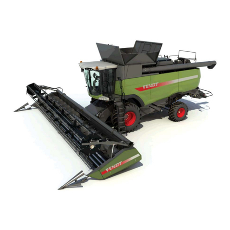
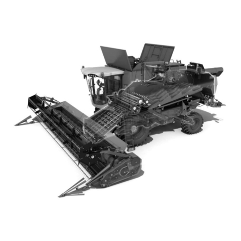
AGCO FENDT 5250L Instruction manual

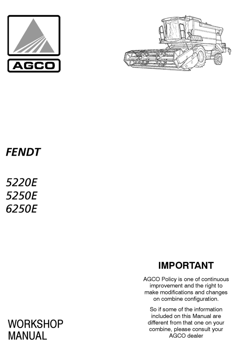
MANUAL
WORKSHOP
FENDT
5250L
5250L AL
6250L
6270L
IMPORTANT
AGCO Policy is one of continuous
improvement and the right to
make modifications and changes
on combine configuration.
So if some of the information
included on this Manual are
different from that one on your
combine, please consult your
AGCO dealer
INTRODUCTORY REMARKS
◊This manual is subdivided in sections marked by two--digit numbers, with independent page numbering within
each section.
For a quick reference, these sections have the same identification number and the same description of the
relevant Flat Time Rate Manual.
◊The dealt matters and the information can be easily detected by index on the following pages.
◊At the bottom of each page there is the manual print number and the relevant publication/up--dating date.
◊The pages of further up--datings shall have the same print number of the current publication, changing the
last digit (for example: first up--dating 327258011; second up--dating 327258012; etc.) and the relevant publi-
cation date.
These pages shall be completed by the new print of the index, duly revised.
◊The information of this manual are up--dated at the date of the publication.
As AGCO continuously improves its product range, some information could be not up--dated due to modifica-
tions of technical or commercial type, as well as for suiting the law regulations of the different countries.
In case of disagreement, refer to AGCO Sales and Service networks.
IMPORTANT CAUTION
◊All repair and maintenance works listed in this manual must be carried out only by staff belonging to the AGCO
Service Network, strictly complying with the instructions given and using, whenever required, the special
tools.
◊Anyone who carries out the above operations without complying with the prescriptions shall be responsible
for the subsequent damages.
◊The Manufacturer and all the organizations of its distribution chain, including -- without limitation -- national,
regional or local dealers, reject any responsibility for damage due to the anomalous behaviour of parts and/or
components not approved by the manufacturer himself, including those used for the servicing or repair of the
product manufactured or marketed by the Manufacturer.
In any case, no warranty is given or attributed on the product manufactured or marketed by the Manufacturer
in case of damages due to an anomalous behaviour of parts and/or components not approved by the Manu-
facturer.
LITERARY AND ARTISTIC COPYRIGHT
OF LAVERDA S.p.A.
No reproduction, though partial, of
text and illustrations allowed
PRINTEDINITALY
AGCO Limited -- Banner Lane -- Coventry -- England CV4 9GF
SERVICE
Print no. 327258010 -- First Edition -- 01--2008
Find manuals at http://best-manuals.com/search?&s=FENDT-LA327258010F.PDF

CONTENT
Sections
-- GENERAL INFORMATION 00...................................
-- ENGINE 10...................................................
-- LIVE PTO 14..................................................
-- TRANSMISSION 21............................................
-- FRONT DRIVE AXLE 25........................................
-- HYDROSTATIC TRANSMISSION 29.............................
-- BRAKES AND CONTROL 33...................................
-- HYDRAULIC SYSTEMS 35.....................................
-- STEERING 41.................................................
-- AXLE AND WHEELS 44........................................
-- CAB CONDITIONING SYSTEM 50...............................
-- ELECTRICAL SYSTEMS 55....................................
-- ATTACHMENTS / HEADERS 58.................................
-- PRODUCT FEEDING 60........................................
-- THRESHING 66...............................................
-- SEPARATION 72..............................................
-- STRAW CHOPPER 73.........................................
-- CLEANING 74.................................................
-- GRAIN STORAGE 80..........................................
Find manuals at http://best-manuals.com/search?&s=FENDT-LA327258010F.PDF
MODEL IDENTIFICATION
5250 L
5250 L AL
6250 L
6270 L
5BS
5BSAL
6AS
6BS
DESCRIPTION OF THE COMBINE IDENTIFICATION NUMBER
a b
d
Example::2581 :2581 10001 :
c
aTechnical type
dIdentification number: 258110001.
It is formed by two parts:
DFirst part (b), formed by 4 numbers ”2581”: it corresponds to the technical type (machine model).
DSecond part (c), formed by 5 numbers ”10001”: they are the production progressive numbers identifying
the progressive number of the produced machine model..
:2581 :2581 . . . .:FOR 5BS MODEL
:2681 :2681 . . . .:FOR 5BS AL MODEL
:5642 :5642 . . . .:FOR 6AS MODELS
:3182 :3182 . . . .:FOR 6BS MODELS
GRAIN HEADER IDENTIFICATION NUMBER
723... ...FOR 4,20 m MODEL
733... ...FOR 4,80 m MODEL
743... ...FOR 5,40 m MODEL
753... ...FOR 6,00 m MODEL
763... ...FOR 6,60 m MODEL
Find manuals at http://best-manuals.com/search?&s=FENDT-LA327258010F.PDF
9
IMPORTANT
THE COMBINE ASSEMBLY, AT THE ARRIVAL TO THE DEALER OR IMPORTER, HAS TO BE MADE FOL-
LOWING THE “ASSEMBLY INSTRUCTION BOOK”.
BEFORE THE DELIVERY OF COMBINE TO THE CUSTOMER, THE PRE--DELIVERY INSPECTION HAS TO
BE MADE FOLLOWING THE P.D.I. MODULE INSTRUCTIONS AS THE ONE REPORTED BELOW.
Find manuals at http://best-manuals.com/search?&s=FENDT-LA327258010F.PDF

10
Find manuals at http://best-manuals.com/search?&s=FENDT-LA327258010F.PDF

11
Dealer Service Schedule
50
Hours
225
Hours
450
Hours
900
Hours
End of
Season 1
End of
Season 2
End of
Season 3
End of
Season 4
Table Header
Grease the knife drive gearbox. X X X X X X X X
Grease the knife head. X X X X X X X X
Check knives and fingers. XXXX
Check auger, auger fingers and flights. XXXX
Check auger slip clutch. XXXX
Check all drive belts and chains. X XXXX
Check reel belt drive variator hubs. XXXX
Check reel tine bars, spiders and bearings. XXXX
Check correct function of the GSAX (Auto Level). XXXX
Main Crop Elevator
Fit any table stabilising devices and detach cutting table from the rump of
the combine. XXXX
Check condition of Prepare & Feeding Roller (PFR system). XXXX
Check condition of elevator slats and conveyor chains. XXXX
Check movement and condition of lower feed roller. XXXX
Inspect and reset slip clutch. XXXX
Check condition and tensioning of elevator and table drive chain. X X X X X X X X
Check condition of top feeder drive shaft. XXXX
Check operation of stone trap. XXXX
Check operation and condition of the table reverse mechanism (at low
engine speed). XXXX
Find manuals at http://best-manuals.com/search?&s=FENDT-LA327258010F.PDF
12
50
Hours
225
Hours
450
Hours
900
Hours
End of
Season 1
End of
Season 2
End of
Season 3
End of
Season 4
Drum, Concave and Threshing area
Check condition of the drive & speed variator mechanism to drum. XXXX
Check condition of the cylinder and rasp bars for wear / damage. XXXX
Inspect condition of concave(s) rub bars and wires. XXXX
Ensure concave(s) are free to move, can be fully adjusted & the clear-
ance is correct. XXXX
Check condition of the drive to the Rotary Separator (MCS). XXXX
Check condition & clearance of the Rotary Separator (MCS) & also for
wear / damage. XXXX
Check condition of cylinder door and seals. XXXX
Inspect rear beater for damage / wear and condition of its drive. XXXX
Check rear beater & concave curtain condition. XXXX
Check all drive belts and chains. X X X X X X
Check condition of straw walkers and sieves. XXXX
Check sealing strips for grain pan and shaker shoe. XXXX
Straw Walkers
Check condition of the drive mechanism. XXXX
Inspect for wear the straw walker crankshafts and bearings / blocks. XXXX
Check condition and adjustment of the straw walker curtain(s). XXXX
Check condition of the straw walkers and risers if fitted. XXXX
Check on condition of sealing rubbers. XXXX
Check condition of sealing rubbers installed for maize. XXXX
Check security and position of grain loss sensors. XXXX
Check on condition of returns pan. XXXX
Check the condition of all drives and mounting bushes / bearings. X X X X X X
Find manuals at http://best-manuals.com/search?&s=FENDT-LA327258010F.PDF
13
50
Hours
225
Hours
450
Hours
900
Hours
End of
Season 1
End of
Season 2
End of
Season 3
End of
Season 4
Cleaning Area
Check sieves will operate through full range of adjustment. XXXX
Remove sieves and grain pan and check for damage.
Protect from rusting. XXXX
Inspect condition of shaker shoe and grain pan frame for cracks or dam-
age. XXXX
Inspect mounting bushes / bearings for wear. X X X X X X
Inspect belt, pulley and pitman drives to sieves. X X X X X X
Check adjustments and timing of shaker shoe drives. XXXX
Inspect condition of all sealing strips. XXXX
Check condition and operation of cleaning fan, including drive belt. XXXX
Check condition and adjustment of air deflectors, fan blades and sealing
strips. XXXX
Inspect condition of cross augers. XXXX
Crop Elevators, Augers and Tank
Check condition of drives to grain elevators. X X X X X X X
Inspect condition of conveying chains and paddles. X X X X X X X
Check elevator top and bottom for wear. XXXX
Check condition and function of bubble up auger. XXXX
Check condition of grain tank discharge system. XXXX
Check grain tank and unloading auger for leaks. XXXX
Check discharge auger angle gear oil. XXXX
Inspect general condition of grain tank including ‘full‘ sensors. XXXX
Inspect returns system slip clutch. XXXX
Inspect and adjust the elevator slip clutch and check condition of the
shear bolts for the discharge auger. XXXX
Find manuals at http://best-manuals.com/search?&s=FENDT-LA327258010F.PDF
14
50
Hours
225
Hours
450
Hours
900
Hours
End of
Season 1
End of
Season 2
End of
Season 3
End of
Season 4
Chaff Spreader and Straw Chopper
Check security and positioning of chaff spreader in / out of operation. XXXX
Check chaff spreader rotors for damage. XXXX
Inspect drive mechanism of chaff spreader. XXXX
Check condition of the straw chopper rotor and condition of all knives. X X X X X X X
Check function and condition of straw deflectors. XXXX
Inspect straw chopper drive and engagement mechanism for wear and
adjustment. XXXX
Change the oil in the main transmission gearbox. X X X X X X
Transmission and Brakes
Check gearbox for leaks and correct oil level. X X
Inspect final drives for oil leaks and correct oil level. X X
Change the oil in the final drives. X X X X X X
Ensure gear selection and external adjustment is correct. XXXX
Ensure hydrostatic transmission operates correctly. XXXX
Look for signs of leakage or damage to hydrostatic pump, motor, hoses
and oil cooler. X X X X X X X X
Change hydrostatic oil. X X X X X X
Check hydrostatic oil level in reservoir. X X
Change hydrostatic pump filter. X X X X X X
Inspect condition of drive shaft couplers to final drive housings. XXXXX
Check the track frame, outer support oil level. X X X X X X
Check the track chain tension. X X X X X X
Check parking brake system for operation and adjustment. X X X X X X
Check independent brakes for operation and balance. X X X X X X
Check brake fluid level. X X X X X X
Change brake fluid and bleed brakes. X X
Assess condition of brake shoes / pads for wear. XXXXX
Check brake lines / hoses for deterioration. XXXXX
Find manuals at http://best-manuals.com/search?&s=FENDT-LA327258010F.PDF
15
50
Hours
225
Hours
450
Hours
900
Hours
End of
Season 1
End of
Season 2
End of
Season 3
End of
Season 4
Hydraulic System
Check oil level in hydraulic system reservoir(s). X X
Change hydraulic oil. X X X X X X
Change hydraulic oil tank return filter. X X X X X X
Inspect main supply and return hoses for leakage. X X X X X X X X
Operate all hydraulic systems through their normal working range and
note any restrictions in either speed or travel. XXXX
Inspect all hydraulic cylinders, hoses and connections for damage or
leaks. X XXXX
Check function of the levelling system (AL only). XXXX
Report any unusual noise or characteristics of the hydraulic pump(s). X X X X X X X X
Electrical System
Check function of all work / inspection lights (Grain Tanks, Sieves, etc.). XXXX
Check battery electrolyte level and cable connections. XXXXX
Inspect general condition of the fuse box for missing or damaged fuses,
diodes and relays. XXXX
Check tightness of all external cable harness connections and common
earth points. XXXX
Inspect cable condition for cracks and chaffing. XXXX
Check function of the main switch and condition of the main battery and
its leads. XXXX
Examine all actuating motors for correct function and signs of damage. XXXX
16
50
Hours
225
Hours
450
Hours
900
Hours
End of
Season 1
End of
Season 2
End of
Season 3
End of
Season 4
Chains, Sprockets, Belts and Pulley
Visually inspect all belts for signs of wear and damage. XXXX
Check the tension of all belts and note any belt drives that have limited
adjustment left on them. XXXXX
Check tension of all belts & inspect for any signs of damage. X XXXX
Inspect all pulleys for signs of wear or damage, any misalignment or
mounting problems. XXXX
Ensure split sheave pulleys travel freely and that the belt does not bot-
tom out. Inspect any safety devices built into belt drives, e.g. friction lin-
ings, etc.
XXXX
Check the condition and tension of all chain drives. X X X X X X
Report any chain wear / damage or sprocket wear / damage. XXXX
Lubricate and protect all roller chains. X X X X X X
Inspect all chain idlers, tensioners and guide blocks for wear / damage. XXXXX
Wheels and Steering
Operate the steering to full lock in each direction, check for smooth oper-
ation and function of stops. XXXXX
Inspect the steering column for correct function and adjustment. XXXX
Inspect the steering linkage, hoses, ball joints and steering rams. XXXXX
Check rear wheel bearings and stub axles for wear. XXXXX
Check tightness and presence of all wheel nuts / studs. XXXXX
Inspect general condition and pressure of all tyres. XXXXX
17
50
Hours
225
Hours
450
Hours
900
Hours
End of
Season 1
End of
Season 2
End of
Season 3
End of
Season 4
Engine
Check the safety (inner) and clean the outer air cleaner elements. X X
Change both the safety (inner) and outer air cleaner elements. X X X X X X
Inspect the air intake system for damage and leaks. XXXXX
Change engine oil and oil filter(s). X X X X X X X X
Check valve tip clearances (replace rocker cover gaskets). X X X
Change engine crankcase vent filters (5 sw. only) X X X X X X
Check level of cooling system and inspect radiator for cleanliness and
leaks. X X X X X X
Change antifreeze in the cooling system plus additive (if supplied). X X
Check cooling system hoses and connections are tight. XXXX
Change fuel sedimentor / water trap element. X X X X X X X
Replace fuel filters. X X X X X X X
Clean the fuel tank water trap. X
Check the rotary air intake and dust extractor. XXXX
Check for leaks in oil, fuel & coolant systems. X X X X X X X X
Check engine fastening screws on cross beams. X X X X X X
Check engine speed range & min. / max. settings. XXXX
Inspect and tension fan, alternator and compressor drive belts. XXXX
Check lubricating pipe for turbocharger. XXXX
Check general condition of fuel tank. XXXX
Ensure hoses, pipes or wiring are not fouling exhaust system and
pulleys, belts, etc. XXXX
18
50
Hours
225
Hours
450
Hours
900
Hours
End of
Season 1
End of
Season 2
End of
Season 3
End of
Season 4
General Machine
Lubricate all grease points. X X X X X X X X
Ensure all table attachment connections operate correctly and safely.
(Mechanical, Hydraulic & Electrical). XXXX
Start engine, check engagement of table and threshing mechanisms. XXXX
Visually examine combine chassis for any signs of damage. XXXX
Check for loose bolts (particularly the undercarriage). X XXXX
Ensure that all safety guards and safety decals are in place. XXXX
Advise customer of winter storage procedure, regular starting, etc. and
vermin protection. XXXX
Check all belts and chains that have not already been inspected. XXXXX
Check all mechanical/electrical clutches. XXXX
Check operation of optional equipment, vertical knife/chaff spreader/
straw chopper/electrical straw deflectors/GSA/maize header etc. (if
fitted).
XXXX
19
50
Hours
225
Hours
450
Hours
900
Hours
End of
Season 1
End of
Season 2
End of
Season 3
End of
Season 4
Operator Environment
Check function of the start, stop and throttle controls. XXXX
Re--set the performed maintenance feature on the computer. XXXX
Change cab air flters. X X X X X X
Check cab air filters. X
Check all instruments & warning systems for correct operation. XXXX
Check operation of electronic/automatic functions. X XXXX
Inspect general condition of cab interior, including seat, radio, etc. XXXX
Report any problems with cab glass, door, locks, ladder, etc. XXXX
Check operation of the onboard computer system. XXXX
Check operation of any monitoring systems, including Datavision. XXXX
Check condition of in--cab control switches for operation of all general
systems such as lights, blowers, windscreen wipers, etc. XXXX
Top up windscreen washer reservoir. XXXX
Check all driving and directional signal lights. XXXX
Check function of all systems controlled by switches and/or Datavision. XXXX
Check function of airconditioning system. XXXX
Replace the receiver dryer. XXXX
Check cutting height presetting/cutting height control and field pressure
control. XXXX
20
NOTE:
SECTION 00 -- GENERAL INFORMATION 1
327 258 010 -- 01 -- 2008
Section 00 -- GENERAL INFORMATION
GENERAL INSTRUCTION
IMPORTANT NOTE
All maintenance and repair works described in this manual must be carried out only by the LAVERDA service net-
work, strictly complying with the instructions given and using the required special tools.
Anybody carrying out the above interventions without strictly complying with the prescriptions is fully responsible
for the occurred damage.
ADJUSTMENT SHIMS
During any adjustment, select the adjustment shims measuring them individually, by a micrometer, and then sum-
ming up the detected values: do not rely on the wrong measurement of the complete pack or on the rated value
stated for each ring.
ROTARY SHAFT SEALS
For correct rotating shaft seal installation, proceed as follows:
-- before assembly, leave the seals in oil bath, for at least half an hour, using the same oil they should contain;
-- carefully clean the shaft and make sure its working surface isn’t damaged;
-- direct the seal edge to the fluid; in case of hydrodynamic edge, the stripes must be directed so that, considering
the shaft rotation direction, the fluid is brought back to the sealing means;
-- lay a thin layer of lubricant on the seal edge (oil rather than grease) and fill with grease the gap between seal
edge and dust edge in case of double edge seals;
-- fit the seal in the relevant housing pressing it or using a drift with flat contact surface; do not beat it with hammer
or drift;
-- during driving, make sure the seal is perpendicular to its housing and, at the end of the driving, make sure it
touches the shoulder;
-- to prevent damaging the seal edge against the shaft, lay a suitable protection during installation of both parts.
”O--RINGS”
Lubricate O--rings before fitting them in their seats to prevent any rolling over and twisting, during assembly/installa-
tion, thus jeopardizing their sealing action.
SEALANTS
Before laying the sealant on the mating surfaces, prepare them as follows:
-- remove possible scales through a metal brush;
-- thoroughly degrease the surfaces by one of the following cleansers: trichloroethylene, oil, or a solution of water
and soda.
COTTER PINS
While fitting split cotter pins, make sure that their groove is directed towards the effort direction, stressing the pin.
Spiral cotter pins do not need any orientation during fitting.
SECTION 00 -- GENERAL INFORMATION2
327 258 010 -- 01 -- 2008
REMARKS ABOUT SPARE PARTS
Use only AGCO genuine parts
Only genuine parts guarantee the same quality, life, safety as original parts, as they are the same as those fitted
during standard production.
Only AGCO genuine spare parts can offer this guarantee.
All spare parts orders must be accompanied by the following data:
-- machine model (commercial name) and frame number;
-- combine type and number;
-- part number of the ordered part, which can be found in the ”Spare Part Catalogue”, used for order processing.
REMARKS ABOUT TOOLS
The tools that AGCO suggests and describes in this manual have been:
-- expressly studied and designed to operate on AGCO range combines;
-- required to get a reliable repair;
-- suitably manufactured and strictly tested to offer efficient and long--lasting working means.
By using these tools, Repair Personnel will benefit from:
-- working in the best technical conditions;
-- getting the best results;
-- saving time and effort;
-- working more safely.
CAUTION
Wear limit values indicated for certain parts should be considered to be recommended, but not binding. The words
”front”, ”rear”, ”right” and ”left” referred to different parts are meant with the operator sitting on the driver’s seat and
directed towards the combine standard running direction.
HOW TO MOVE THE COMBINE WITHOUT BATTERY
The cables of the outer power supply unit must be connected only to the relevant terminals of the negative and posi-
tive cables of the combine using efficient pliers to get a suitable and stable contact.
Disconnect all services (lights, windscreen wipers, etc...) before starting the combine.
If the operating efficiency of the combine electrical system must be checked, proceed only after connecting the
power supply unit. At the end of the check, disconnect all the services and switch the power supply off before discon-
necting its cables.
SECTION 00 -- GENERAL INFORMATION 3
327 258 010 -- 01 -- 2008
SAFETY REGULATIONS
PAY ATTENTION TO THIS SYMBOL
This warning symbol points out important messages involving your personal safety.
Carefully read all the suggested safety precautions to avoid potential hazards and
safeguard your health and personal safety.
In this manual you will find this symbol together with the following key words:
WARNING -- In case of warning aimed at preventing unsuitable repair works, involving
potential hazards to the operator’s safety.
DANGER -- Specific warnings concerning potential hazards for operator safety or for
other persons directly or indirectly involved.
AVOID ACCIDENTS
Most accidents and injuries occurring in workshops
are due to the lacked compliance with some simple
and fundamental caution and safety rules. For this rea-
son, IN MOST CASES THEY CAN BE PREVENTED:
just consider the possible causes in advance and act
consequently, with the required caution and care.
Accidents may occur with all types of machine, regard-
less of how well the machine in question was designed
and built.
A cautious and careful mechanician is the best war-
ranty against accidents.
Precise observance of the most basic safety rule is
normally sufficient to avoid many serious accidents.
DANGER. Never carry out any cleaning, lubrication or
maintenance operation when the engine is running.
SAFETY REGULATIONS
GENERAL FEATURES
◊Strictly comply with the specified maintenance and
repair procedures.
◊Never wear rings, watches, jewels, loose or unbut-
toned clothing such as ties, torn clothes, scarves,
open jackets or shirts with open zips which could
get trapped in moving parts. It is recommended to
wear clothes approved as for accident prevention,
such as anti--skid shoes, gloves, safety goggles,
helmets, etc...
◊Never carry out any repair intervention on the ma-
chine if someone is sitting on the driver’s seat, ex-
cept for authorized operators assisting in the oper-
ation to be carried out.
◊Never operate the machine or use attachments
from a place other than sitting in the operator’s
seat.
◊Never carry out any intervention on the machine
when the engine is running, except when specifi-
cally indicated.
◊Stop the engine and make sure all pressure is re-
lieved from hydraulic circuits before removing
caps, covers, valves, etc...
◊All service interventions must be carried out with
the utmost care and attention.
◊Service stairs and ladders used in the workshop on
in the field should be built in compliance with the
safety regulations in force.
◊Disconnect the batteries and label all controls to
warn that the machine is being serviced. Lock the
machine and all the equipment to be lifted.
◊Never check or fill fuel tanks, accumulator bat-
teries, nor use starting fluid while smoking or next
to open flames, as the concerned fluids are flam-
mable.
◊Brakes are ineffective when manually released for
service interventions: in such cases, make sure
you can keep the machine under continuous con-
trol through suitable locks or other.
◊The fuel supply gun must always touch the filler
neck. Keep it there until fuel supply stops, to pre-
vent sparks due to static electricity build--up.
SECTION 00 -- GENERAL INFORMATION4
327 258 010 -- 01 -- 2008
◊Use only the prescribed points for towing the ma-
chine. Make the connection with the utmost care:
make sure that the envisaged pins and/or catches
are securely tightened before towing. Never re-
main near the towing bars, cables or chains that
are operating under load.
◊To transfer a faulty machine, use a trailer or low
loading platform trailer, when available.
◊To load and unload the machine from the trans-
portation means, select a flat area providing a firm
support to the wheels of the trailer or truck. Se-
curely fasten the machine to the platform of the
truck or the trailer and lock the wheels as required
by the shipping agent.
◊For electrical heaters, battery--chargers and simi-
lar equipment, use exclusively auxiliary power
supplies providing an efficient ground to avoid
electrical shock hazards.
◊While lifting or carrying heavy parts, use hoists and
similar equipment, with a suitable capacity.
◊Pay special attention to the presence of by--stand-
ers.
◊Never pour gasoline or diesel oil in open, wide and
low containers.
◊Never use gasoline, diesel oil or other flammable
liquids as cleansers: use non--flammable and non--
toxic standard solvents.
◊Wear goggles with side guards while cleaning
parts by compressed air.
◊Reduce air pressure according to the local or
national regulations in force.
◊Never operate the machine in closed areas, with-
out proper ventilation.
◊Do not smoke, use open flames, nor cause sparks
nearby when refilling or handling highly flammable
matters.
◊Do not use flames as light sources when servicing
the machine or checking for possible ”leaks”.
◊Move with caution when working under the ma-
chine, on the machine itself or nearby. Wear the
prescribed safety equipment: helmets, special
goggles and shoes.
◊During checks to be made with engine running,
ask an operator to sit on the driver’s seat and keep
the service technician under constant visual con-
trol at any time.
◊In case of servicing operations to be made outside
the workshop, drive the combine to a flat area and
lock it. If the work on hillsides cannot be avoided,
first lock the machine and move it to a level ground,
as soon as you can do it within a given safety mar-
gin.
◊Dented and bent chains or ropes aren’t reliable: do
not use them for lifting or towing. Always use suit-
able protective gloves when handling chains or
cables.
◊The chains must be tightly fastened: make sure
the fastening device is strong enough to hold the
envisaged load. No people should stand next to
the towing connection, chains or ropes.
◊The area for servicing operations should be kept
always CLEAN and DRY. Immediately remove any
water deposits or oil stains.
◊Do not pile up oil or grease soaked rags: they are
a great fire hazard. Always place them in a closed
metal container.
Before starting the machine or the equipment
check, adjust and lock the operator’s seat. Make
sure no person is standing in the machine or equip-
ment operating range.
◊Do not carry in your pockets any object that could
accidentally fall in the machine inner compart-
ments.
◊Whenever you might be hit by projecting metal
parts and other, wear an eye mask or goggles with
side guards, helmets, special footwear and heavy
gloves.
◊During welding operations, use the special safety
guards: face shield or dark goggles, helmets, over-
alls, special gloves and footwear. Dark goggles
must be worn also by bystanders, if they need to
remain next to the operator carrying out welding
operations. NEVER LOOK DIRECTLY AT THE
WELDING ARC WITHOUT SUITABLE EYE
PROTECTION.
◊Metal cables, when used, get frayed: always wear
suitable protection while handling them (heavy
gloves, goggles, etc...).
◊Handle all parts with the utmost care. Keep your
hands and fingers away from gaps, gears and
others. Always wear the approved protection de-
vices, such as safety goggles, safety gloves and
shoes.

This manual suits for next models

3

Other AGCO Farm Equipment manuals

AGCO TG9300B User manual

AGCO

AGCO TG9300B User manual

AGCO FENDT 5220E Instruction manual

AGCO

AGCO FENDT 5220E Instruction manual

AGCO Glencoe DR8700 User manual

AGCO

AGCO Glencoe DR8700 User manual

AGCO Valtra BC 800 User manual

AGCO

AGCO Valtra BC 800 User manual

AGCO LELY ATTIS PT 130 User manual

AGCO

AGCO LELY ATTIS PT 130 User manual

AGCO MASSEY FERGUSON 7380 CENTORA Combine Series Instruction manual

AGCO

AGCO MASSEY FERGUSON 7380 CENTORA Combine Series Instruction manual

AGCO Glencoe ULTRAMULCHER UM43 21' User manual

AGCO

AGCO Glencoe ULTRAMULCHER UM43 21' User manual

AGCO RoGator 900 User manual

AGCO

AGCO RoGator 900 User manual

AGCO GSI PNEG-2064 User manual

AGCO

AGCO GSI PNEG-2064 User manual

AGCO 5270C User manual

AGCO

AGCO 5270C User manual

AGCO New Leader L4258G4 User manual

AGCO

AGCO New Leader L4258G4 User manual

AGCO HayBoss G2 600A1 User manual

AGCO

AGCO HayBoss G2 600A1 User manual

AGCO Laverda Combines M400 User manual

AGCO

AGCO Laverda Combines M400 User manual

AGCO Hawkeye RoGator RG900 User manual

AGCO

AGCO Hawkeye RoGator RG900 User manual

AGCO HayBoss G2 644A User manual

AGCO

AGCO HayBoss G2 644A User manual

AGCO Combine CEREA 7274 User manual

AGCO

AGCO Combine CEREA 7274 User manual

AGCO VALTRA MOMENTUM Series User manual

AGCO

AGCO VALTRA MOMENTUM Series User manual

AGCO FENDT 870N User manual

AGCO

AGCO FENDT 870N User manual

AGCO GSI 54 User manual

AGCO

AGCO GSI 54 User manual

AGCO 1800 Series Operating instructions

AGCO

AGCO 1800 Series Operating instructions

AGCO Challenger RoGator 600C User manual

AGCO

AGCO Challenger RoGator 600C User manual

AGCO FENDT 700 Vario SCR Stage 3B User manual

AGCO

AGCO FENDT 700 Vario SCR Stage 3B User manual

AGCO Challenger Terra Gator 3244 User manual

AGCO

AGCO Challenger Terra Gator 3244 User manual

AGCO Combine FENDT 8300 User manual

AGCO

AGCO Combine FENDT 8300 User manual

Popular Farm Equipment manuals by other brands

HE-VA Sub-Tiller Series Operating Instructions, Declaration of Conformity, Spare Parts List

HE-VA

HE-VA Sub-Tiller Series Operating Instructions, Declaration of Conformity, Spare Parts List

horsch Joker RT Series owner's manual

horsch

horsch Joker RT Series owner's manual

Tanco A Series Operator's handbook

Tanco

Tanco A Series Operator's handbook

KLUNDER KL 2000 Operating and maintenance instructions

KLUNDER

KLUNDER KL 2000 Operating and maintenance instructions

Schulte SMR-600 Operator's manual

Schulte

Schulte SMR-600 Operator's manual

Krone Swadro 700 operating instructions

Krone

Krone Swadro 700 operating instructions

MacDon R216 installation instructions

MacDon

MacDon R216 installation instructions

Tatu Marchesan PST Plus instruction manual

Tatu Marchesan

Tatu Marchesan PST Plus instruction manual

Poettinger NOVACAT 225 H Operator's manual

Poettinger

Poettinger NOVACAT 225 H Operator's manual

GREAT PLAINS 1510HDF Operator's manual

GREAT PLAINS

GREAT PLAINS 1510HDF Operator's manual

SIP STAR 850/26 Instruction for work

SIP

SIP STAR 850/26 Instruction for work

agromaster OT 40 Operator's manual

agromaster

agromaster OT 40 Operator's manual

STEELGREEN SG36 instruction manual

STEELGREEN

STEELGREEN SG36 instruction manual

Buffalo Tools CKNPLKR Assembly & operating instructions

Buffalo Tools

Buffalo Tools CKNPLKR Assembly & operating instructions

WIL-RICH 11 XL2 Series Assembly manual

WIL-RICH

WIL-RICH 11 XL2 Series Assembly manual

LELY Hibiscus 915 CD Vario Operator's manual

LELY

LELY Hibiscus 915 CD Vario Operator's manual

Classen HTS-20HE Operator's manual

Classen

Classen HTS-20HE Operator's manual

Raven RS1 installation manual

Raven

Raven RS1 installation manual

manuals.online logo
manuals.online logoBrands
  • About & Mission
  • Contact us
  • Privacy Policy
  • Terms and Conditions

Copyright 2025 Manuals.Online. All Rights Reserved.