manuals.online logo
Brands
  1. Home
  2. •
  3. Brands
  4. •
  5. Agora Models
  6. •
  7. Toy
  8. •
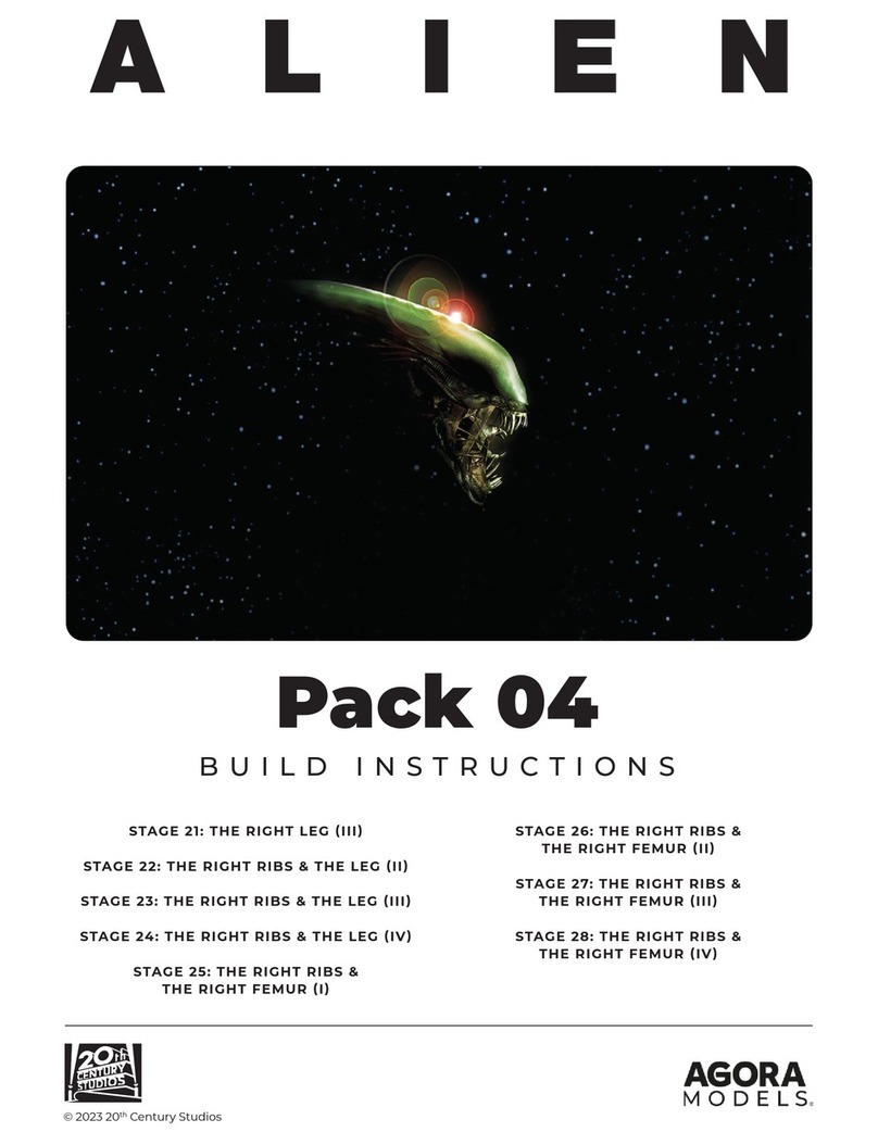
  9. Agora Models ALIEN Pack 03 Manual

Agora Models ALIEN Pack 03 Manual

1PB
ALIENALIEN
Pack 03
BUILD INSTRUCTIONS
© 2023 20th Century Studios
STAGE 13: THE HEAD AND THE SKULL (II)
STAGE 14: THE SKULL & THE RIGHT LEG (I)
STAGE 15: THE SKULL & THE RIGHT LEG (II)
STAGE 16: THE SKULL & THE RIGHT LEG (III)
STAGE 17: THE RIGHT LEG (I)
STAGE 18: THE RIGHT LEG (II)
STAGE 19: THE RIGHT RIBS
STAGE 20: THE RIBS & THE RIGHT LEG (I)
2PB
WARNING: Some parts are assembled using magnets. These magnets can cause serious injury if they are
swallowed. Keep away from children. If you suspect a magnet has been swallowed, seek medical help
straight away.
All parts belong to a kit. Collectors item for adults.
Not suitable for children under 14.
Some parts may have sharp edges, please handle them with care.
The installation of electronic parts must always be carried out by an adult. When replacing batteries, use
the same type of batteries.
Please ensure that the battery compartment is securely fastened before you use the model.
Used batteries should be recycled.
Please make sure to check with your local authority how batteries should be disposed of in your area.
Batteries can present a choking danger to small children and may cause serious harm if ingested. Do not
leave them lying around and keep any spare batteries locked away at all times.
Before you start...
!
To help you get the best out of building the Xenomorph, we’ve prepared a modellers checklist
with hints, tips and advice from our expert. The information below is aimed at making your
build as enjoyable and professional as possible right from the start.
Make sure you have good ventilation when using adhesives and to replace
caps firmly.
Always use the correct adhesives and always follow manufacturers guidance.
Apply glue sparingly and use a cocktail stick to apply so that you don’t use too
much nor apply the glue too heavily.
Work in a well lit area. Use an anglepoise lamp or similar on your work bench to ensure you
have good light whenever you’re at work.
Organise storage – stackable, labeled containers like old clean takeaway or ice-cream plastic
tubs with lids are perfect. Small parts which may not be needed until a later stage should be
kept in clear plastic and labeled bags.
Use masking tape to hold parts temporarily in place.
Only use the correct size screwdriver that fits the screw head firmly.
Cut parts from a sprue (framework) with side cutters or a craft knife. Side cutters tend to be
easiest.
Use a magnet to help find screws that have fallen on the floor.
Leave parts in the paper bags supplied until they are needed. You can write a note of the stage
and part on the paper bag too.
If a screw is tight, try turning a half turn forwards followed by a quarter turn backwards. Also, it
can sometimes help to temporarily fit a screw into its hole before assembling the parts.
But most of all, enjoy your build!
3PB
ASSEMBLY GUIDE
In this stage you will continue to assemble different parts of the
Xenomorph’s head and skull.
STAGE 13: THE HEAD
AND THE SKULL (II)
13-1 13-2
13-4
13-3
13-5
PARTS SUPPLIED
Ref. Name Qty.
13-1 Lower Back Part of the Head 1
13-2 Pipe R1 1
13-3 Pipe R2 1
Ref. Name Qty.
13-4 Pipe R3 1
13-5 2.3x6mm screws 3*
*A spare screw is supplied in case of loss or damage.
4PB
STAGE 13: THE HEAD AND THE SKULL (II)
1
Take the Lower Back Part
of the Head 13-1 and
Pipe R1 13-2. Test-fit
the pipe before gluing in
place, as shown.
13-2 (R1)
13-1
EXPERT ADVICEEXPERT ADVICE
From this stage onwards, the Pipes provided will be attached to small numbered tabs which will allow for quick identication.
Before adding them to the assembly, gently twist the tab to remove it from the piece.
5PB
STAGE 13: THE HEAD AND THE SKULL (II)
2
3
13-5
13-1
13-3
(R2)
1-1
7-1
9-1
Take the head assembly you
worked on in stage 12 and
orientate Head part 13-1 as
shown. The tabs on Head part
13-1 (circled) fit over raised
screw sockets on parts 7-1
and 9-1. Fix in place with two
2.3x6mm screws 13-5.
Next, take the skull
assembly which was
also worked on in the
last stage. After test-
fitting the tabs of Pipe R2
13-3 into the slots on
the right-hand side of the
skull 1-1, glue in place.
6PB
STAGE 13 IS COMPLETE
4
1-1
13-3
(R2)
3-1
13-4 (R3)
Further parts have been
fitted to the head and
skull.
To finish, test-fit the tabs
on Pipe R3 13-4 into the
next three slots and glue
in place.
STAGE 13: THE HEAD AND THE SKULL (II)
7PB
ASSEMBLY GUIDE
In this stage you will continue to add appendages to the skull as well as
working on parts of the right calf.
STAGE 14: THE SKULL &
THE RIGHT LEG (I)
14-1
14-2 14-3
14-4 14-5
PARTS SUPPLIED
Ref. Name Qty.
14-1 Skin (right calf) 1 1
14-2 Pipe A1 (skull) 1
14-3 Pipe A2 (skull) 1
Ref. Name Qty.
14-4 Pipe A3 (skull) 1
14-5 Magnets 4
8PB
STAGE 14: THE SKULL & THE RIGHT LEG (I)
1
2
3
14-2 (A1)
14-3 (A2)
14-4
(A3)
5-1
14-2 (A1)
5-1
3-1
Finish the line of pipes
along the right side of the
skull by fitting Pipe A3
14-4. Check the fit and
glue firmly in place.
Repeat the previous step
to secure Pipe A2 14-3
as a continuation of Pipe
A1 14-2.
Take the skull assembly which was
worked on in the last stage and
continue fitting the pipes on the
right-hand side. Check the fit of
Pipe A1 14-2 and glue firmly in
place on skull part 3-1.
9PB
STAGE 14: THE SKULL & THE RIGHT LEG (I)
4
14-5
14-1
14-5
14-5
14-5
STAGE 14 IS COMPLETE MORE PIPES HAVE BEEN SECURED
TO THE SKULL AND MAGNETS
FITTED TO THE RIGHT CALF SKIN.
Finally, take the Calf Skin 14-1
and fit the four Magnets 14-5
into the circular recesses as
shown on the left. Secure them in
place with a little glue. This time,
it doesn’t matter which way round
the magnets are fitted.
EXPERT TIP: As some of
the skin parts look quite similar,
it may help to label the inside
of the part. This could be done
by writing the part number on a
small piece of masking tape.
10 PB
ASSEMBLY GUIDE
In this stage you will continue to add appendages to the skull as well as
working on parts of the right calf.
STAGE 15: THE SKULL &
THE RIGHT LEG (II)
15-1
15-4
15-6 15-7
15-5
15-2 15-3
PARTS SUPPLIED
Ref. Name Qty.
15-1 Right Tibia 1 1
15-2 Connector 1
15-3 Pipe R4 1
15-4 Pipe R5 1
Ref. Name Qty.
15-5 Pipe R7 1
15-6 Pipe R6 1
15-7 2.3x6mm screws 2*
*A spare screw of each type is supplied in case of loss or damage.
11 PB
STAGE 15: THE SKULL & THE RIGHT LEG (II)
1
2
3
15-3 (R4)
15-4 (R5) 15-3 (R4)
1-1
5-1 3-1
15-7
15-2
15-1
3-1 Take the skull assembly you
worked on in the previous stage.
Check that the tabs on Pipe R4
15-3 fit correctly into the notches
underneath the Skull 1-1 and 3-1,
then fix in place with a little glue.
The pipe may need to be stretched
slightly to fit.
Repeat the previous step to fit
Pipe R5 15-4 into the notches
underneath parts 3-1 and 5-1 so
that it continues Pipe R4 15-3. A
peg at the end of Pipe 15-4 fits
into a hole in part 5-1. Again, the
pipe may need to be stretched
slightly to fit.
Take the Right Tibia 15-1 and the
Connector 15-2. The Connector
is fitted, as shown on the left and
secured in place with a 2.3x6mm
screw 15-7. Put the part aside until
it is needed in the next stage.
12 PB
STAGE 15: THE SKULL & THE RIGHT LEG (II)
45
14-1
15-5 (R7) 15-6 (R6)
14-1
15-5 (R7)
STAGE 15 IS COMPLETE
MORE PIPES HAVE BEEN FITTED TO
THE SKULL AND CALF SKIN ALONG
WITH A CONNECTOR ON THE TIBIA.
Take the right Calf Skin 14-1,
supplied with the previous stage,
along with the Pipe R7 15-5. Before
fixing in place with a little glue,
check that the tabs on Pipe R7
15-5 fit properly into the slots on
the Calf Skin 14-1. Hold in place
until the glue has set.
Repeat the previous step to attach
Pipe R6 15-6 to the Calf Skin 14-1.
Pipe R6 15-6 is a continuation of
Pipe R7 15-5. Again, hold the pipe
in place until the glue has set.
13 PB
ASSEMBLY GUIDE
In this stage you will continue to add appendages to the skull as
well as starting work on building the right tibia.
STAGE 16: THE SKULL
AND THE RIGHT LEG (III)
16-1 16-2
16-616-516-416-3
PARTS SUPPLIED
Ref. Name Qty.
16-1 Right Tibia 1
16-2 Pipe R8 (skull) 1
16-3 Pipe R9 (skull) 1
Ref. Name Qty.
16-4 Pipe R10 (skull) 1
16-5 Magnets 4
16-6 2.3x6 mm screws 2*
*A spare screw is supplied in case of loss or damage.
14 PB
STAGE 16: THE SKULL & THE RIGHT LEG (III)
1
2
1-1
1-2
16-2 (R8)
16-3 (R9)
Check that the tabs on
Pipe R9 16-3 fit correctly
into the slots in the
underside of the left part
of the Jaw 1-2. Once
happy with the fit, glue the
pipe in place.
Take the skull assembly that you
worked on in the previous stage.
Check that the Pipe R8 16-2 fits
correctly in place at the front of the
Skull 1-1. Study the ends of the
pipe closely and note that there is
a hole at each end that fits over a
peg each side of the skull part 1-1.
When sure of a good fit, apply a
little glue to the tabs on Pipe R8
16-2 and the pegs on skull part
1-1 and secure the pipe in place.
15 PB
STAGE 16: THE SKULL & THE RIGHT LEG (III)
3
4
1-2
16-4 (R10)
16-6
15-1
16-1
15-2
Repeat the previous step
to fit the Pipe R10 16-4
underneath the other side
of the Jaw 1-2.
Taking the Tibia 15-1 from the last stage
along with Tibia 16-1, join the parts
together using the Connector 15-2 then
secure the parts with a 2.3x6mm screw
16-6 as shown.
16 PB
STAGE 16 IS COMPLETE
5
6
15-1
16-1
14-1
16-5
15-1
16-1
More pipes have been fitted to the skull and
work has continued on the right leg.
Put the head safely aside until it is needed
in a later stage.
Take the Right Calf Skin 14-1 which
was worked on in stage 14 and the
Tibia parts 15-1/16-1. Place the
Tibia 15-1/16-1 on top of the
Right Calf Skin 14-1, as shown.
To hold the skin to the tibia, Magnets
16-5 will now be tted to the assembly
15-1/16-1. To do this, slot a Magnet
16-5 into the rst recess on the left. The
magnetic pole is automatically attracted
towards the magnet already tted below on
the Calf Skin 14-1. If tted incorrectly, the
poles will repel and the magnet may even
jump out of the recess.
In a similar manner, t the remaining
magnets. Again, the magnets already in
place below will attract the magnets to be
tted. When you are happy with the polarity
of the Magnets 16-5, glue in place.
STAGE 16: THE SKULL & THE RIGHT LEG (III)
17 PB
ASSEMBLY GUIDE
In this stage you will continue to assemble parts of the right tibia and leg.
STAGE 17: THE RIGHT
LEG(I)
17-1
17-2 17-3 17-4
PARTS SUPPLIED
Ref. Name Qty.
17-1 Right Tibia 1 1
17-2 Connector 1
Ref. Name Qty.
17-3 Magnets 4
17-4 2.3x6mm screws 2*
*A spare screw is supplied in case of loss or damage.
18 PB
STAGE 17: THE RIGHT LEG (I)
1
2
3
17-2
17-4
17-2
17-1
17-1
17-3
4-4
17-3
Place the Right Tibia 17-1
on the work surface and
note from the diagram how
Connector 17-2 fits into the
oval recess on part 17-1.
Take the right calf assembly
4-4 which was last worked
on in stage 4. Fit two
Magnets 17-3 into the
circular recesses, as shown,
and secure in place with a
little glue. It doesn’t matter
which way up the magnets
are fitted.
Use a 2.3x6mm
screw 17-4 to fix the
Connector 17-2 in place.
19 PB
STAGE 17: THE RIGHT LEG (I)
4
17-3
4-4
17-3
WORK HAS CONTINUED ON THE
RIGHT LEG WITH A CONNECTOR AND
MAGNETS BEING ADDED.
Repeat the previous step
to add the remaining two
Magnets 17-3 to part 4-4,
as shown. Again, it doesn’t
matter which way up the
magnets are tted.
STAGE 17 IS COMPLETE
20 PB
ASSEMBLY GUIDE
In this stage you will continue to assemble parts of the right leg.
STAGE 18: THE RIGHT
LEG (II)
18-1
18-4
18-2
18-3
PARTS SUPPLIED
Ref. Name Qty.
18-1 Right Tibia 1
18-2 Connectors 4
Ref. Name Qty.
18-3 Magnets 4
18-4 2.3x6 mm screws 10*
*A spare screw is supplied in case of loss or damage.

Other Agora Models Toy manuals

Agora Models Hachette Mitsubishi A6MZERO FIGHTER Manual

Agora Models

Agora Models Hachette Mitsubishi A6MZERO FIGHTER Manual

Agora Models OPTIMUS PRIME Pack 04 Manual

Agora Models

Agora Models OPTIMUS PRIME Pack 04 Manual

Agora Models CORVETTE STING RAY 1963-Z06/N03 Manual

Agora Models

Agora Models CORVETTE STING RAY 1963-Z06/N03 Manual

Agora Models OPTIMUS PRIME Pack 01 Manual

Agora Models

Agora Models OPTIMUS PRIME Pack 01 Manual

Agora Models OPTIMUS PRIME Pack 03 Manual

Agora Models

Agora Models OPTIMUS PRIME Pack 03 Manual

Agora Models OPTIMUS PRIME Pack 02 Manual

Agora Models

Agora Models OPTIMUS PRIME Pack 02 Manual

Agora Models FERRARI 312 T4 User manual

Agora Models

Agora Models FERRARI 312 T4 User manual

Agora Models Lamborghini MIURA Manual

Agora Models

Agora Models Lamborghini MIURA Manual

Agora Models OPTIMUS PRIME Manual

Agora Models

Agora Models OPTIMUS PRIME Manual

Agora Models Mitsubishi A6M ZERO Fighter Manual

Agora Models

Agora Models Mitsubishi A6M ZERO Fighter Manual

Agora Models Bismarck Manual

Agora Models

Agora Models Bismarck Manual

Agora Models Bismarck 08 Manual

Agora Models

Agora Models Bismarck 08 Manual

Agora Models Mitsubishi A6M ZERO Fighter Manual

Agora Models

Agora Models Mitsubishi A6M ZERO Fighter Manual

Agora Models OPTIMUS PRIME Pack 05 Manual

Agora Models

Agora Models OPTIMUS PRIME Pack 05 Manual

Agora Models Mitsubishi A6M ZERO Fighter Manual

Agora Models

Agora Models Mitsubishi A6M ZERO Fighter Manual

Agora Models LONDON TRANSPORT ROUTEMASTER RM 857 Manual

Agora Models

Agora Models LONDON TRANSPORT ROUTEMASTER RM 857 Manual

Agora Models Mitsubishi A6M ZERO Fighter Manual

Agora Models

Agora Models Mitsubishi A6M ZERO Fighter Manual

Agora Models Mitsubishi A6M ZERO Fighter Manual

Agora Models

Agora Models Mitsubishi A6M ZERO Fighter Manual

Agora Models Hachette Mitsubishi A6MZERO FIGHTER Manual

Agora Models

Agora Models Hachette Mitsubishi A6MZERO FIGHTER Manual

Agora Models ALIEN Manual

Agora Models

Agora Models ALIEN Manual

Agora Models JAGUAR E-TYPE Manual

Agora Models

Agora Models JAGUAR E-TYPE Manual

Agora Models FERRARI 312 T4 User manual

Agora Models

Agora Models FERRARI 312 T4 User manual

Agora Models Hachette Mitsubishi A6MZERO FIGHTER Manual
Agora Models

Agora Models Hachette Mitsubishi A6MZERO FIGHTER Manual

Agora Models FDNY FIRE TRUCK TOWER LADDER 9 Manual

Agora Models

Agora Models FDNY FIRE TRUCK TOWER LADDER 9 Manual

Popular Toy manuals by other brands

Mattel Barbie M4215 instructions

Mattel

Mattel Barbie M4215 instructions

LEGO The Hobbit - An Unexpected Journey 3920 manual

LEGO

LEGO The Hobbit - An Unexpected Journey 3920 manual

Smoby 140103 manual

Smoby

Smoby 140103 manual

Eduard P-51B Mustang placards S.A. manual

Eduard

Eduard P-51B Mustang placards S.A. manual

Thames & Kosmos WIND POWER Experiment manual

Thames & Kosmos

Thames & Kosmos WIND POWER Experiment manual

Eduard Bf 109E-7 interior S.A. manual

Eduard

Eduard Bf 109E-7 interior S.A. manual

Trix BR 150 22151 manual

Trix

Trix BR 150 22151 manual

Align T-REX 450X manual

Align

Align T-REX 450X manual

Topmodel Precision Products micro Bullit manual

Topmodel

Topmodel Precision Products micro Bullit manual

Trix VT 75.9 manual

Trix

Trix VT 75.9 manual

LEGO 60096 manual

LEGO

LEGO 60096 manual

MadLab WIND GENERATOR manual

MadLab

MadLab WIND GENERATOR manual

Eduard Zoom Bf 109F-2 Weekend Assembly instructions

Eduard

Eduard Zoom Bf 109F-2 Weekend Assembly instructions

PEEQ Qball Quick setup guide

PEEQ

PEEQ Qball Quick setup guide

Mattel Hot Wheels GBF81 instructions

Mattel

Mattel Hot Wheels GBF81 instructions

RTS 1S18 VINTAGE SPECTATOR OUTLOOK Assembly instructions

RTS

RTS 1S18 VINTAGE SPECTATOR OUTLOOK Assembly instructions

eKids Dreamworks Trolls TR-615 quick guide

eKids

eKids Dreamworks Trolls TR-615 quick guide

Fisher-Price Hot Wheels Dune Racer W6201 Owner's manual with assembly instructions

Fisher-Price

Fisher-Price Hot Wheels Dune Racer W6201 Owner's manual with assembly instructions

manuals.online logo
manuals.online logoBrands
  • About & Mission
  • Contact us
  • Privacy Policy
  • Terms and Conditions

Copyright 2025 Manuals.Online. All Rights Reserved.