manuals.online logo
Brands
  1. Home
  2. •
  3. Brands
  4. •
  5. Agora Models
  6. •
  7. Toy
  8. •
  9. Agora Models Mitsubishi A6M ZERO Fighter Manual

Agora Models Mitsubishi A6M ZERO Fighter Manual

STAGE 46: ATTACHING THE TYPE 99
MKII 20 MM MACHINE GUN TO THE
RIGHT LANDING GEAR
STAGE 47: ATTACHING THE RIGHT LANDING
GEAR AND MOTOR
STAGE 48: INSTALLING THE RIGHT AILERON
STAGE 49: INSTALLING RIGHT WING
SUPPORT FITTINGS, THE EXTERNAL PANEL
FRAME AND THE COCKPIT
STAGE 50: ASSEMBLING THE TAIL GEAR
RETRACTION MECHANISM
STAGE 51: CHECKING THE ELEVATOR
SERVOMOTOR
STAGE 52: ASSEMBLING THE RIGHT
LANDING GEAR (1)
STAGE 53: TESTING THE SERVOMOTOR
AND ASSEMBLING THE TAIL GEAR
RETRACTION MECHANISM (3)
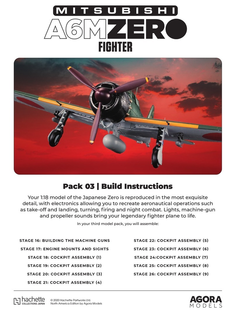
Pack 06 |Build Instructions
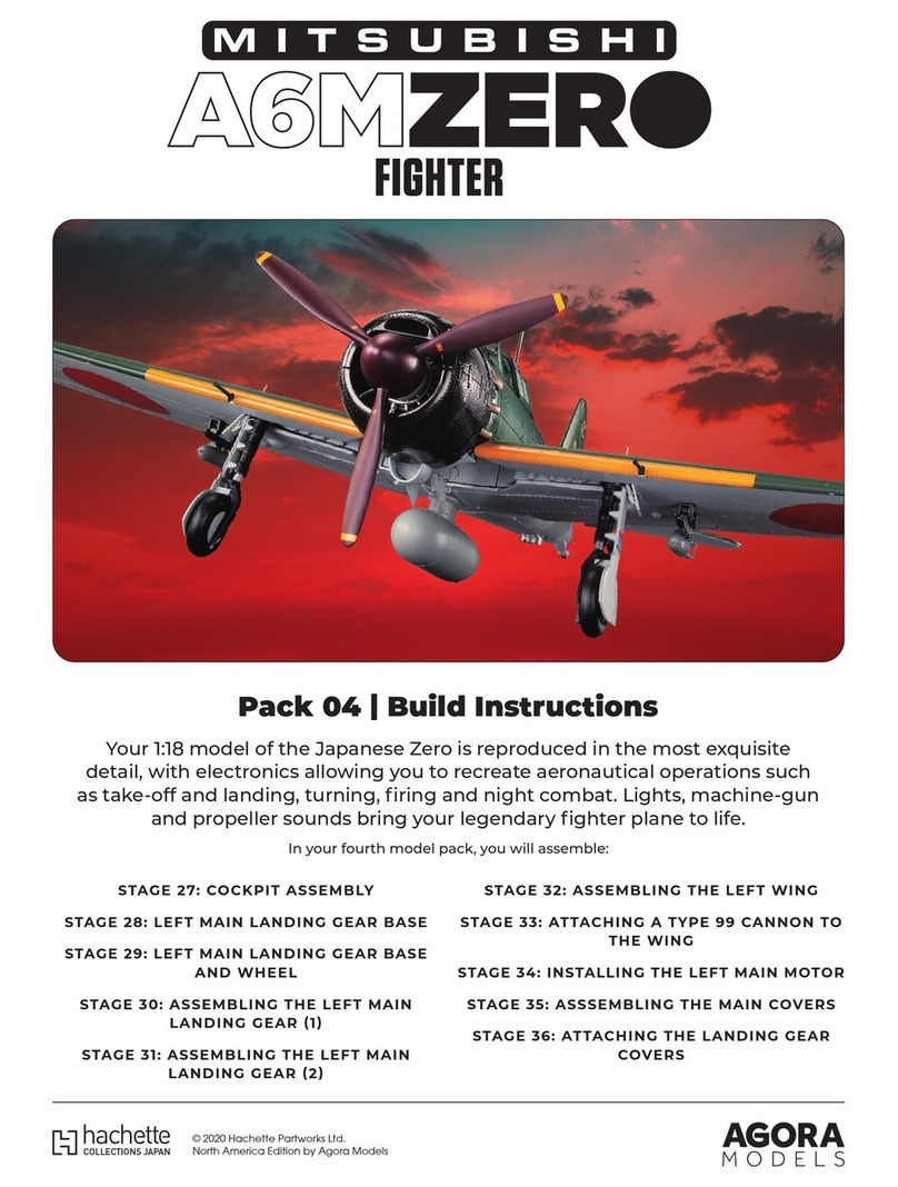
Your 1:18 model of the Japanese Zero is reproduced in the most exquisite
detail, with electronics allowing you to recreate aeronautical operations such
as take-off and landing, turning, firing and night combat. Lights, machine-gun
and propeller sounds bring your legendary fighter plane to life.
In your sixth model pack, you will assemble:
© 2020 Hachette Partworks Ltd.
North America Edition by Agora Models
2
AGORAMODELS A6M ZERO
Not suitable for children under the age of 14. This product is not a toy and is not designed for use in play. Keep
the parts out of the reach of small children. Some parts may have sharp edges. Please handle them with care.
Advice from the experts
Spare screws are included with each part. Occasionally, you may
be instructed to keep spare or unused screws for a later stage.
Keep these spares in a safe place and label them correctly.
Please make sure you don’t mix up the screws. They look quite
similar, but the threads do vary slightly. Using the wrong screws
may damage the parts.
When securing parts together using multiple screws, fit each
screw loosely to ensure all the parts are correctly aligned before
gently tightening them firmly, but not overtight, in the order in
which you placed them.
The screwdriver can be magnetised by stroking it with a magnet
(fridge magnet, etc.) enabling it to hold the screws and make
assembly easier.
If a screw is tight going into a metal part, do not force it as you
may shear the head off. Remove it and put a tiny smear of Vaseline,
soap or light oil on the thread. That will lubricate it and make it
easier to drive home.
During the course of this build, you will receive many pieces that
you will assemble immediately – following the instructions in the
corresponding stage – and other pieces that you should store
safely to one side, for use in future assembly stages.
When gluing parts together, glue may be applied to either of the
two parts. Some experts find it asier to apply glue to a hole rather
than a pin. Choose a method that works best for you.
It's a good idea to test fit your parts so that you can check their
positioning before gluing.
There are excellent videos showing
how to build the Zero here.
You will also need: tweezers, screwdriver, needle-nose pliers
046-01 046-02
046-03 046-04
046-01
046-02
046-03
046-04
Switch board
LED
Steel
ABS resin
1
1
4
1
(1 spare)
MATERIALNo.PART
STAGE 46 PARTS PARTS LIST
Stage 46 Assembly
Landing Gear & Machine Gun
Stage 46: Attaching the Type
99 MkII 20 mm Machine Gun
to the Right Landing Gear
In this stage we’ll be installing the landing gear
limit switch as well as assembling the Type 99
mk II 20 mm machine gun and then attaching
this to the landing gear frame.
組み立てガイド組み立てガイド
3
AGORAMODELS A6M ZERO
Attaching the landing gear limit switch
STEP 1
NOTE
Since the LED has a hard
metal wire, if you try to install
it as it is, the metal wire will
get in the way. Hold the area
just below the LED with
needle-nose pliers and bend
the metal wire with your
fingers.
Installing the right landing gear
STEP 2
Assembling and attaching the Type 99 mkII 20 mm machine gun
STEP 3
046-04
046-02
044-04
044-02
Fit the right landing gear assembled in stage 43 into the right
wing frame 044-01.
Fix the right landing gear with 1 x 044-02
(thick one) and 1 x 044-04 (thin one) screw
that came with stage 44.
Insert LED 046-02 into the Type 99 20-millimeter machine gun (right) 046-04.
1
2
1
044-01
044-01
046-01
041-11
041-11
046-03
Place the right landing gear limit switch 046-01 on the right wing frame 044-01, and fix it with two screws 046-03. The cord of the
switch 046-01 should be fed out through the hole of the wing frame 044-01. The screw on the left is fixed by sandwiching the washer,
so be careful not to shift the washer 041-11.。
Place the washer 041-1 1 on the right wing frame 044-01 so that the holes match.
2
1
:Glue
:Don’t Glue
:Glue
:Don’t Glue
組み立てガイド組み立てガイド
4
AGORAMODELS A6M ZERO
Attaching the landing gear limit switch
STEP 1
NOTE
Since the LED has a hard
metal wire, if you try to install
it as it is, the metal wire will
get in the way. Hold the area
just below the LED with
needle-nose pliers and bend
the metal wire with your
fingers.
Installing the right landing gear
STEP 2
Assembling and attaching the Type 99 mkII 20 mm machine gun
STEP 3
046-04
046-02
044-04
044-02
Fit the right landing gear assembled in stage 43 into the right
wing frame 044-01.
Fix the right landing gear with 1 x 044-02
(thick one) and 1 x 044-04 (thin one) screw
that came with stage 44.
Insert LED 046-02 into the Type 99 20-millimeter machine gun (right) 046-04.
1
2
1
044-01
044-01
046-01
041-11
041-11
046-03
Place the right landing gear limit switch 046-01 on the right wing frame 044-01, and fix it with two screws 046-03. The cord of the
switch 046-01 should be fed out through the hole of the wing frame 044-01. The screw on the left is fixed by sandwiching the washer,
so be careful not to shift the washer 041-11.。
Place the washer 041-1 1 on the right wing frame 044-01 so that the holes match.
2
1
:Glue
:Don’t Glue
:Glue
:Don’t Glue
組み立てガイド組み立てガイド
5
AGORAMODELS A6M ZERO
The machine gun (right) 046-04 assembled in 1 is installed in the right main wing frame 044-01. The wire of LED 046-02 should be
fed through the same hole as the wire of the right landing gear limit switch 046-01.
The machine gun 046-04 is fixed with 1 x 046-03 screw .
046-03
046-04
2
3
STAGE COMPLETE
組み立てガイド組み立てガイド
6
AGORAMODELS A6M ZERO
You will also need: screwdriver
047-01
047-02
Plastic
Motor
1
1
047-01
047-02
MATERIALNo.PART
STAGE 47 PARTS PARTS LIST
Stage 47 Assembly
Right Landing Gear Motor
Stage 47: Attaching the
Right Landing Gear and
Motor
In this stage we’ll attach the right landing gear as well
as the motor (which drives this side forward) to the
left wing frame. Be careful when installing the gears
and make sure the motor gears properly engage.
組み立てガイド組み立てガイド
7
AGORAMODELS A6M ZERO
組み立てガイド組み立てガイド
Attaching the right landing gear and motor
STEP 1
NOTE
Make sure the landing gear and motor gear properly engage
when installing these parts
3
45
045-01
047-02
047-01
045-06
1
2
045-05
045-03
045-03
044-01
STAGE COMPLETE
:Glue
:Don’t Glue
8
AGORAMODELS A6M ZERO
組み立てガイド組み立てガイド
Attaching the right landing gear and motor
STEP 1
NOTE
Make sure the landing gear and motor gear properly engage
when installing these parts
3
45
045-01
047-02
047-01
045-06
1
2
045-05
045-03
045-03
044-01
STAGE COMPLETE
:Glue
:Don’t Glue
9
AGORAMODELS A6M ZERO
You will also need: screwdriver, tweezers, superglue.
048-01
048-02
048-03
048-04
048-05
048-06
048-07
048-01
048-02
048-03
048-04
048-05
048-06
048-07
ABS resin
ABS resin
ABS resin
ABS resin
Steel
Steel
Steel
1
1
1
1
1
3
7
(1 spare)
MATERIALNo.PART
STAGE 48 PARTS PARTS LIST
Stage 48 Assembly
Aileron
Stage 48: Installing the
Right Aileron
In this stage we’ll be installing the right
aileron. Not inserting or fitting small parts
properly or having them in a skewed
position means the model won’t work later.
組み立てガイド組み立てガイド
10
AGORAMODELS A6M ZERO
Assembling the aileron base (R)
STEP 1
048-03
048-07
044-03
036-01
048-04
048-05
048-06
Installing the right wing
STEP 2
Insert the hinges 048-06 into the three grooves of the aileron base 048-04 with the notches facing down, and lower the fastener
048-03 on top.
Fix the fastener 048-03 to the aileron base 048-04 with 4 x
screws 048-07.
Pass shaft 048-05 through the holes in hinges 048-06.
1
2 3
Fit the right wing assembled in stage 47 into the right side of the main wing base frame 036-01 of the body to which the left wing
was attached in stage 40.
Fix the right wing with the 4 screws 044-03 that came with stage 44.
1
2
Align each of the 4 screw holes
:Glue
:Don’t Glue
組み立てガイド組み立てガイド
11
AGORAMODELS A6M ZERO
Assembling the aileron base (R)
STEP 1
048-03
048-07
044-03
036-01
048-04
048-05
048-06
Installing the right wing
STEP 2
Insert the hinges 048-06 into the three grooves of the aileron base 048-04 with the notches facing down, and lower the fastener
048-03 on top.
Fix the fastener 048-03 to the aileron base 048-04 with 4 x
screws 048-07.
Pass shaft 048-05 through the holes in hinges 048-06.
1
2 3
Fit the right wing assembled in stage 47 into the right side of the main wing base frame 036-01 of the body to which the left wing
was attached in stage 40.
Fix the right wing with the 4 screws 044-03 that came with stage 44.
1
2
Align each of the 4 screw holes
:Glue
:Don’t Glue
組み立てガイド組み立てガイド
12
AGORAMODELS A6M ZERO
組み立てガイド組み立てガイド
048-07
048-01
044-01
048-02
Installing the right aileron
STEP 3
Fit the aileron base assembled in STEP 1 into the right wing
frame 044-01.
Fix the aileron base in place with 2 x screws 048-07.
Apply a small amount of superglue to the 10 lugs on the aileron underside 048-02 (see stage 39 "STEP 2 Installing the aileron") and
attach to the aileron base in 2. Place the shaft 048-05 and the hinges 048-06 in the grooves and then lower the upper surface of the
aileron 048-01 on top, squeezing the glued lugs into the corresponding recesses to fix.
3
1 2
STAGE COMPLETE
13
AGORAMODELS A6M ZERO
You will also need: screwdriver, tweeers.
049-05
049-06
049-02
049-01 049-03
049-04
049-01
049-02
049-03
049-04
049-05
049-06
Steel
Steel
Steel
Steel
Steel
ABS resin
2
3
5
7
1
1
(1 spare)
(1 spare)
(1 spare)
(1 spare)
MATERIALNo.PART
STAGE 49 PARTS PARTS LIST
Stage 49 Assembly
Metal Support Bar, External
Panel Frame & Cockpit
Stage 49: Installing Right Wing
Support Fittings, the External
Panel Frame and the Cockpit
In this stage we’ll be installing support fittings for the left wing as well as the frame we’ll
attach the external panels to later. We’ll also attach the cockpit to the wing main frames.
組み立てガイド組み立てガイド
14
AGORAMODELS A6M ZERO
Installing the right wing support fittings
STEP 1
049-06
049-04
049-05
044-01
049-02
049-01
Installing the external panel frame
STEP 2
Installing the cockpit
STEP 3
1
2
1 2
NOTE
There are four types of screws. Be careful not to make a mistake.
1
2
Fit the metal support bar 049-05 into the right wing frame 044-01 assembled in stage 48.
Cover the right main wing frame 044-01 with the external panel frame 049-06. Align the 6 screw holes and 6 pins of 049-06 with the
corresponding parts of the wing frame.
Fix in place with 4 x screws 049-04.
Extend the wire of connector 015-06 from the carburettor and
supercharger unit attached to the wing base frame 036-01 to the
rear and pass it between the two cylinders on the left side of the
wing base frame 036-01.
Extend the wire of the machine gun magazine circuit board
020-01 from the cockpit assembled in stage 27 backward and
pass it between the two cylinders on the right side of the main
wing base frame 036-01.
Fix in place with 1 x screw 049-01 and 2 x screws 049-02.
049-01 049-02 049-03 049-04
036-01
044-01
:Glue
:Don’t Glue
組み立てガイド組み立てガイド
15
AGORAMODELS A6M ZERO
Installing the right wing support fittings
STEP 1
049-06
049-04
049-05
044-01
049-02
049-01
Installing the external panel frame
STEP 2
Installing the cockpit
STEP 3
1
2
1 2
NOTE
There are four types of screws. Be careful not to make a mistake.
1
2
Fit the metal support bar 049-05 into the right wing frame 044-01 assembled in stage 48.
Cover the right main wing frame 044-01 with the external panel frame 049-06. Align the 6 screw holes and 6 pins of 049-06 with the
corresponding parts of the wing frame.
Fix in place with 4 x screws 049-04.
Extend the wire of connector 015-06 from the carburettor and
supercharger unit attached to the wing base frame 036-01 to the
rear and pass it between the two cylinders on the left side of the
wing base frame 036-01.
Extend the wire of the machine gun magazine circuit board
020-01 from the cockpit assembled in stage 27 backward and
pass it between the two cylinders on the right side of the main
wing base frame 036-01.
Fix in place with 1 x screw 049-01 and 2 x screws 049-02.
049-01 049-02 049-03 049-04
036-01
044-01
:Glue
:Don’t Glue
組み立てガイド組み立てガイド
16
AGORAMODELS A6M ZERO
Insert the cockpit so that the carburettor and supercharger of the main wing base frame 036-01 can be inserted into the silver frame
at the tip of the cockpit. The black cylindrical part on the left back of the carburettor and supercharger gets in the way, so it's a good
idea to insert it diagonally from the left back.
The wires for connector 015-06 and machine gun magazine
circuit board 020-01 should pass outside the cockpit rear
bulkhead 026-02.
Fix the cockpit in place with 4 x screws 049-03.
NOTE
If there is a gap between the main wing base frame and the
silver frame at the tip of the cockpit, the wire of connector
015-06 is caught, so insert it by pressing it against the front
partition wall with tweezers.
3
4
026-02
015-06
STAGE COMPLETE
組み立てガイド組み立てガイド
17
AGORAMODELS A6M ZERO
You will also need: screwdriver, tweezers.
050-01 050-02
050-05050-04
050-07
050-03 050-06
050-01
050-02
050-03
050-04
050-05
050-06
050-07
050-08
050-09
ABS resin
ABS resin
Plastic
Plastic
Plastic
Plastic
Steel
Steel
Steel
1
1
1
1
1
1
1
3
2
(1 spare)
(1 spare)
050-08 050-09
STAGE 50 PARTS PARTS LIST
Stage 50 Assembly
Tail Gear Retraction
Mechanism
MATERIALNo.PART
Stage 50: Assembling
the Tail Gear Retraction
Mechanism
The A6M Zero Type 52 was designed such that when in
flight both the main and rear landing gear would retract
into the body of the plane, coming back out for landings.
In this stage we’ll assemble the gearbox for the tail gear
retraction mechanism, so make sure the gears are facing
in the right direction when working through those steps.
18
AGORAMODELS A6M ZERO
組み立てガイド組み立てガイド
Inserting the gears
STEP 1
Fit the clutch 050-05 into
the gearbox 050-02.
1
2
3 4
5
6 7
8
NOTE
If you make a mistake on the front and
back of the gear, it will not operate
normally. Make sure they are combined
as shown in the picture.
Fit the gear 050-06 into the clutch 050-05 installed in 1.
Cover the gearbox 050-02 with the gear cover 050-01.
Secure the gear cover 050-01 with 2 x screws 050-08.
Fix the arm 050-03 with 1 x screw 050-09.
Fit the arm 050-03 onto the shaft of the clutch 050-05.
Insert the shaft 050-07 into the gearbox
050-02.
Fit the gear 050-04 into the shaft 050-07
attached in 3.
050-05
050-01
050-03
050-09
050-08
050-06
050-02
050-07
050-04 050-07
050-04
050-06
:Glue
:Don’t Glue
STAGE COMPLETE
19
AGORAMODELS A6M ZERO
組み立てガイド組み立てガイド
Inserting the gears
STEP 1
Fit the clutch 050-05 into
the gearbox 050-02.
1
2
3 4
5
6 7
8
NOTE
If you make a mistake on the front and
back of the gear, it will not operate
normally. Make sure they are combined
as shown in the picture.
Fit the gear 050-06 into the clutch 050-05 installed in 1.
Cover the gearbox 050-02 with the gear cover 050-01.
Secure the gear cover 050-01 with 2 x screws 050-08.
Fix the arm 050-03 with 1 x screw 050-09.
Fit the arm 050-03 onto the shaft of the clutch 050-05.
Insert the shaft 050-07 into the gearbox
050-02.
Fit the gear 050-04 into the shaft 050-07
attached in 3.
050-05
050-01
050-03
050-09
050-08
050-06
050-02
050-07
050-04 050-07
050-04
050-06
:Glue
:Don’t Glue
STAGE COMPLETE
20
AGORAMODELS A6M ZERO

Other manuals for Mitsubishi A6M ZERO Fighter

5

Other Agora Models Toy manuals

Agora Models Bismarck 08 Manual

Agora Models

Agora Models Bismarck 08 Manual

Agora Models OPTIMUS PRIME Pack 03 Manual

Agora Models

Agora Models OPTIMUS PRIME Pack 03 Manual

Agora Models CORVETTE STING RAY 1963-Z06/N03 Manual

Agora Models

Agora Models CORVETTE STING RAY 1963-Z06/N03 Manual

Agora Models FERRARI 312 T4 User manual

Agora Models

Agora Models FERRARI 312 T4 User manual

Agora Models OPTIMUS PRIME Pack 01 Manual

Agora Models

Agora Models OPTIMUS PRIME Pack 01 Manual

Agora Models Mitsubishi A6M ZERO Fighter Manual

Agora Models

Agora Models Mitsubishi A6M ZERO Fighter Manual

Agora Models Hachette Mitsubishi A6MZERO FIGHTER Manual

Agora Models

Agora Models Hachette Mitsubishi A6MZERO FIGHTER Manual

Agora Models Hachette Mitsubishi A6MZERO FIGHTER Manual

Agora Models

Agora Models Hachette Mitsubishi A6MZERO FIGHTER Manual

Agora Models Bismarck Manual

Agora Models

Agora Models Bismarck Manual

Agora Models FDNY FIRE TRUCK TOWER LADDER 9 Manual

Agora Models

Agora Models FDNY FIRE TRUCK TOWER LADDER 9 Manual

Agora Models FERRARI 312 T4 User manual

Agora Models

Agora Models FERRARI 312 T4 User manual

Agora Models LONDON TRANSPORT ROUTEMASTER RM 857 Manual

Agora Models

Agora Models LONDON TRANSPORT ROUTEMASTER RM 857 Manual

Agora Models Mitsubishi A6M ZERO Fighter Manual

Agora Models

Agora Models Mitsubishi A6M ZERO Fighter Manual

Agora Models FERRARI 312 T4 User manual

Agora Models

Agora Models FERRARI 312 T4 User manual

Agora Models OPTIMUS PRIME Manual

Agora Models

Agora Models OPTIMUS PRIME Manual

Agora Models ALIEN Pack 03 Manual

Agora Models

Agora Models ALIEN Pack 03 Manual

Agora Models Lamborghini MIURA Manual

Agora Models

Agora Models Lamborghini MIURA Manual

Agora Models Mitsubishi A6M ZERO Fighter Manual

Agora Models

Agora Models Mitsubishi A6M ZERO Fighter Manual

Agora Models ALIEN Manual

Agora Models

Agora Models ALIEN Manual
Agora Models OPTIMUS PRIME Pack 04 Manual

Agora Models

Agora Models OPTIMUS PRIME Pack 04 Manual

Agora Models Hachette Mitsubishi A6MZERO FIGHTER Manual
Agora Models

Agora Models Hachette Mitsubishi A6MZERO FIGHTER Manual

Agora Models Mitsubishi A6M ZERO Fighter Manual

Agora Models

Agora Models Mitsubishi A6M ZERO Fighter Manual

Agora Models OPTIMUS PRIME Pack 02 Manual

Agora Models

Agora Models OPTIMUS PRIME Pack 02 Manual

Agora Models ALIEN Pack 04 Manual

Agora Models

Agora Models ALIEN Pack 04 Manual
Popular Toy manuals by other brands

Hasbro Disney Princess Rainbow Style Rapunzel Hair... Assembly instructions

Hasbro

Hasbro Disney Princess Rainbow Style Rapunzel Hair... Assembly instructions

Betzold Compra Noise Control PRO instructions

Betzold

Betzold Compra Noise Control PRO instructions

Eduard P-61B interior manual

Eduard

Eduard P-61B interior manual

Rompa Rainbow in my Room manual

Rompa

Rompa Rainbow in my Room manual

ItsImagical fresh & fun instructions

ItsImagical

ItsImagical fresh & fun instructions

The Learning Journey Techno Gears Aero Trax Plane 2.0 instruction manual

The Learning Journey

The Learning Journey Techno Gears Aero Trax Plane 2.0 instruction manual

POLA G Grange festive Assembly Intructions

POLA G

POLA G Grange festive Assembly Intructions

WowWee Fingerlings user manual

WowWee

WowWee Fingerlings user manual

QABA 3A0-008 Assembly instruction

QABA

QABA 3A0-008 Assembly instruction

Eduard Mosquito B Mk.IX exterior / engines 1/32 quick start guide

Eduard

Eduard Mosquito B Mk.IX exterior / engines 1/32 quick start guide

Eduard 648 526 quick guide

Eduard

Eduard 648 526 quick guide

LEGO CREATOR 5893 Building instructions

LEGO

LEGO CREATOR 5893 Building instructions

Eduard ZOOM B-26C Invader manual

Eduard

Eduard ZOOM B-26C Invader manual

Talon BADGER CLASS ASSAULT DROPSHIP Assembly instructions

Talon

Talon BADGER CLASS ASSAULT DROPSHIP Assembly instructions

Fisher-Price Animal Sounds Farm 77746 manual

Fisher-Price

Fisher-Price Animal Sounds Farm 77746 manual

Lionel F3ABA owner's manual

Lionel

Lionel F3ABA owner's manual

GREAT PLANES SEAWIND RP RX-R instruction manual

GREAT PLANES

GREAT PLANES SEAWIND RP RX-R instruction manual

Horizon Hobby E-FLITE Carbon-Z T-28 instruction manual

Horizon Hobby

Horizon Hobby E-FLITE Carbon-Z T-28 instruction manual

manuals.online logo
manuals.online logoBrands
  • About & Mission
  • Contact us
  • Privacy Policy
  • Terms and Conditions

Copyright 2025 Manuals.Online. All Rights Reserved.