manuals.online logo
Brands
  1. Home
  2. •
  3. Brands
  4. •
  5. Agora Models
  6. •
  7. Toy
  8. •
  9. Agora Models Bismarck 06 Manual

Agora Models Bismarck 06 Manual

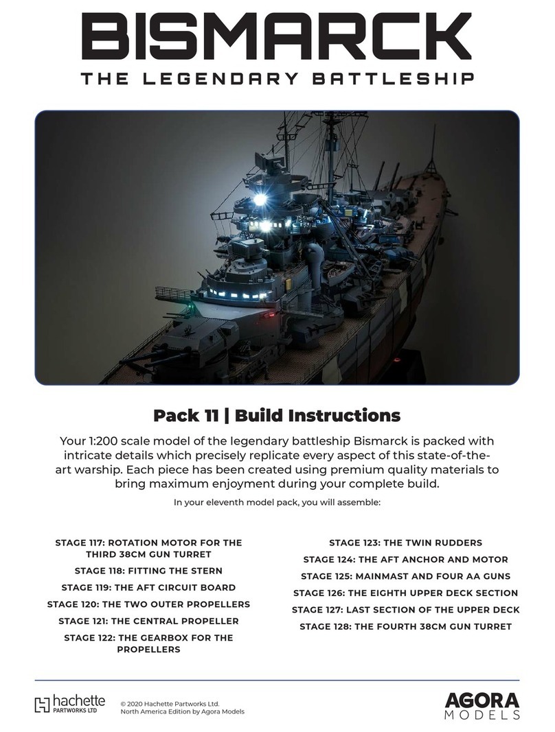
Pack 06 |Build Instructions
Your 1:200 scale model of the legendary battleship Bismarck is packed with
intricate details which precisely replicate every aspect of this state-of-the-
art warship. Each piece has been created using premium quality materials to
bring maximum enjoyment during your complete build.
In your sixth model pack, you will assemble:
© 2020 Hachette Partworks Ltd.
North America Edition by Agora Models
STAGE 57: THE FIRST 15CM TURRET AND
A CIRCUIT BOARD
STAGE 58: MOTOR FOR THE FIRST 15CM
TURRET
STAGE 59: THE NEXT HULL SECTION
STAGE 60: THE NEXT HULL SECTION
STAGE 61: SECOND 15CM GUN TURRET
AND THE FUNNEL
STAGE 62: THE MOTOR FOR THE SECOND
15CM GUN TURRET
STAGE 63: TWO SEARCHLIGHTS FOR THE
FUNNEL
STAGE 64: THE NEXT SECTION OF THE UPPER
DECK
STAGE 65: TWO MORE SEARCHLIGHTS
STAGE 66: THE NEXT SECTION OF THE HULL
STAGE 67: THE THIRD 15CM GUN TURRET
STAGE 68: THE NEXT SECTION OF THE HULL
Not suitable for children under the age of 14. This product is not a toy and is not designed for use in play. Keep
the parts out of the reach of small children. Some parts may have sharp edges. Please handle them with care.
Advice from the experts
Spare screws are included with each part. Occasionally, you may
be instructed to keep spare or unused screws for a later stage.
Keep these spares in a safe place and label them correctly.
Please make sure you don’t mix up the screws. They look quite
similar, but the threads do vary slightly. Using the wrong screws
may damage the parts.
When securing parts together using multiple screws, fit each
screw loosely to ensure all the parts are correctly aligned before
gently tightening them firmly, but not overtight, in the order in
which you placed them.
Your screwdriver can be magnetised by stroking it with a magnet
(fridge magnet, etc.) enabling it to hold the screws and make
assembly easier.
If a screw is tight going into a metal part, do not force it as you
may shear the head off. Remove it and put a tiny smear of Vaseline,
soap or light oil on the thread. That will lubricate it and make it
easier to drive home.
During the course of this build, you will receive many pieces that
you will assemble immediately – following the instructions in the
corresponding stage – and other pieces that you should store
safely to one side, for use in future assembly stages.
22
AGORAMODELS BISMARCK PB
AGORAMODELS BISMARCK
01. FITTING THE ARTILLERY TARGET FINDERS
AND SEARCHLIGHT DIRECTORS
STAGE 57
THE FIRST 15CM TURRET AND
A CIRCUIT BOARD
01 02
5701
5705
5706
B2
B1 PWB
PB
1.7 x 6
PB
2 x 5
5702 5703
5704
5707
5708 5709
A2
A2 A1
B1 B3B4
2902 2902
A1
A1
COMPONENTS CHECKLIST
57-01: Gun turret housing (Port I)
57-02: 15cm gun barrels with
cradle
57-03: Base of the 15cm gun
turret
57-04: Cog
57-05: Two artillery target finders
(A1) and six searchlight
directors (A2)
57-06: Mast support platform
and antenna outriggers
57-07: Cable and switch
57-08: Cable label
57-09: Circuit board
PB: Two 2 x 5mm PB screws
PB: Four 1.7 x 6mm PB screws
PWB: Two 2.3 x 4mm PWB
scews
Cut the two artillery target finders A1 from frame
57-05. Take the forward superstructure assembly and
use a little superglue to fix one of the target finders
A1 to the port side of decking 29-02 as shown.
On the starboard side of the superstructure, glue
the second target finder A1 to the decking 29-02
as shown.
33
AGORAMODELS BISMARCK PB
AGORAMODELS BISMARCK
03 04
05 06
Cut the six searchlight directors A2 from frame 57-05.
Fix three to the port side of the superstructure, gluing
them into the recesses in decking 29-02 as shown.
Glue the remaining three searchlight directors A2 in
place in the recesses on the starboard side of decking
29-02 as shown.
Cut part B4 from frame 57-06. Bend the sides up at
right angles, as shown.
Cut the platform B2 from frame 57-06. Bend the
railings up at right angles, as shown.
02. DETAILS FOR THE FORWARD SUPERSTRUCTURE
01 02
There are two tabs at the sides of the floor of platform
B2. Bend them up at right angles, as shown (arrows).
Cut the antenna outriggers B3 from the frame 57-06.
There are two small pegs on the end of the part (inset,
arrows). Find the matching holes in the underside of
the searchlight platform 40-03 on the starboard side.
Apply a little superglue to the pegs and fix in place.
2902
A2
2902
A2
B3
B4
B2
B2
4003
03 04
44
AGORAMODELS BISMARCK 5
AGORAMODELS BISMARCK
05 06
Repeat to fix the second antenna outrigger B3 to the
underside of the searchlight platform 40-03 on the
port side.
Fit the support B4 to the underside of the foretop
gallery 38-02 so that the straight edge of the tapered
sides is flush with the underside of the gallery, as
shown. When you are happy with the fit, apply a little
superglue and fix in place.
09 10
Repeat to fix the second outrigger B1 to the underside
of the aft port corner of the foretop gallery 38-02.
This view of the superstructure shows the details from
frame 57-06 in place.
07 08
Fit the floor of the platform B2 to the underside of
the foretop gallery 38-02, between the tapered
sides of the support B4, as indicated by the arrows.
When you are happy with the fit, apply superglue to
the flat floor surface and fix in place.
Cut the two antenna outriggers B1 from the frame
57-06. Note the two pegs on the end (inset) and
identify two matching recesses on the underside of
the foretop gallery 38-02 on the aft starboard corner.
Apply a little superglue to the pegs and fix in place.
4003
B3
B43802
B2
B1
B1
B1
3802
3802
B4
3802
B1
B3 B2
5
4
AGORAMODELS BISMARCK 5
AGORAMODELS BISMARCK
03. ASSEMBLING AND FITTING THE FIRST 15CM GUN TURRET
01 02
05 06
Turn the gun turret housing 57-01 upside down and
insert the gun barrels 57-02 through the two
openings in the housing. The ends of the cradle
should rest in the supports (arrows).
Fit the base of the turret 57-03 over the housing. Fix
in place with a single PB 2 x 5mm screw.
Fix the cog 57-04 to the base 57-03 with three 1.7 x
6mm PB screws. Wrap the cable label 57-08 round
the end of the cable 57-07 close to the connector as
shown (inset).
Fit the switch into the recess on the underside of the
upper deck 22-01. Fix in place with a single PWB
screw, as shown.
03 04
Take the upper deck structure 19-01/22-01/48-01. Fit
the 15cm gun turret base 57-01/57-02 on the port
barbette 22-02 as shown.
Carefully holding the 15cm gun turret in place, turn
the deck over. Fit the cog 57-04 onto the gun turret
base 57-03 as shown (arrow), so that the screw holes
are aligned and the peg on the cog fits into the recess
in the base (circled in blue).
5702
2202
5703
PWB
5701
5701
PB
2 x 5
2201
1901
5701
5703
5704
5708
5704
5703
PB 1.7 x 5
5707
2201
5707
4801
66
AGORAMODELS BISMARCK 7
AGORAMODELS BISMARCK
04. TESTING THE MOTORS AND LIGHTS
02
01 First, we test the two radar units, 34-02
and 37-02. In order to do this, connect the
battery box 4-07 to the circuit board 4-06.
Plug the cable marked B-18 into the free
socket on the circuit board 4-06. Now switch
the battery box to “On”. The radar
unit 37-02 will turn. Switch off the battery
box before proceeding. Connecting cable B-19
to the circuit board 4-06 turns the radar unit
34-02. You can also test the firing of the second
38cm gun turret by plugging the cable marked
B-21 into the circuit board (inset).
NOTE: Extreme care is needed when
testing the LED lights. Only connect
them to the new circuit board 57-09,
otherwise permanent damage could
occur.
Next, we test the lights of the forward
superstructure. With the battery box
switched off, remove the circuit board
4-06 and plug in the circuit board
57-09. Plug the cable marked B-9 into
the free socket on the circuit board. Now
switch on the battery box: the
searchlight 40-07 comes on. Switch off
the battery box before continuing.
Next we test the lights of the forward
superstructure. It is essential that this is
only done with the new circuit board
57-09. By plugging different cables
into the circuit board 57-09, different
lights can be switched on, as follows:
B-5: Green navigation light
B-6: Red navigation light
B-7: Bridge light
B-8: Lights on the admiral’s bridge
B-9: Searchlight
NOTE: Always switch off the power
supply when connecting or
disconnecting cables.
5709
407
406
B18
3702
3402
407
B9
4007
B9
B8
B5
B7
B6
03
B18
7
6
AGORAMODELS BISMARCK 7
AGORAMODELS BISMARCK
PB
5801
5802
5805
5802
5803
5804 5805
01. FIXING THE MOTOR TO THE UPPER DECK
STAGE 58
MOTOR FOR THE FIRST 15CM TURRET
01
COMPONENTS CHECKLIST
58-01: Motor (controls the
rotation of the gun)
58-02: Cable for the motor
58-03: Cog
58-04: Motor housing
58-05: Cable label
PB: Three 2 x 5mm PB screws
Take the cable 58-02 and the cable
label 58-05. The plug at one end will
connect to the motor and the other
should be labelled with part 58-05.
The plugs at each end of the cable are
identical.
88
AGORAMODELS BISMARCK PB
AGORAMODELS BISMARCK
5801
5803
5801
5802
2201
5801
5803
5704
02
03
04
Fit the unmarked end of the connector
on cable 58-02 into the socket of the
motor 58-01 as shown.
Fit the drive cog 58-03 onto the shaft
of the motor 58-01 with the ribs of the
cog away from the motor, as shown.
The cog is quite a loose fit on the shaft
of the motor.
Take the upper deck assembly 19-01/22-
01/48-01 from the previous stage and
carefully turn it upside down. Fit the
motor 58-01 into the recess on the
underside of the deck section 22-01.
Ensure that the two cogs are properly
engaged (arrow).
99
AGORAMODELS BISMARCK 10
AGORAMODELS BISMARCK
PB
5804
5801
5804
5801
05
06
Fit the housing 58-04 over the motor
58-01 so that the screw holes in the
housing are aligned with the sockets in
the upper deck, as shown.
Completed work
The motor that controls rotation of the
first 15cm gun turret has been fitted to
the underside of the upper deck.
Fix the housing in place with two PB
screws.
10
9
AGORAMODELS BISMARCK 10
AGORAMODELS BISMARCK
01. ADDING DETAILS TO THE FORWARD SUPERSTRUCTURE
STAGE 59
THE NEXT HULL SECTION
01
Take part 59-03 and position it across the central railings
43-08 (1) which protrude from the front of the lower
searchlight deck, above the bridge. The centre tab on part
59-03 is fitted to the top of the railings. When you are
happy with the fit, glue it in place.
5901
PM
5903 5902
3702
5902
5903 4308 1
Remove part 59-02 from the frame. Check the fit on
top of the radar unit 37-02 on the foretop gallery.
Apply a tiny bit of superglue to the feet of the
mooring manoeuvre light 59-02 and fix in place.
02
COMPONENTS CHECKLIST
59-01: Lower port hull
section
59-02: Mooring
manoeuvre light
59-03: Framework PM: Four 2 x 4 PM
screws
11 11
AGORAMODELS BISMARCK PB
AGORAMODELS BISMARCK
02. FITTING THE NEXT HULL SECTION
PM
5901
4601
5601
5901
Place the hull assembly on your work
surface. Take the lower port hull section
59-01 and fit it in place so that the raised
screw sockets fit into the sockets on
parts 46-01 and 56-01 as shown.
Fix the hull section 59-01 in place with
three PM screws.
Completed work
The next hull section has been added,
and details have been added to the
forward superstructure.
01
02
12 12
AGORAMODELS BISMARCK PB
AGORAMODELS BISMARCK
01. SHAPING AND ASSEMBLING THE PLATFORM
STAGE 60
THE NEXT HULL SECTION
01
PM
6001
6002
A
BD
C
A
COMPONENTS CHECKLIST
60-01: Starboard lower hull section
60-02: Platform (parts A, B, C and D)
PM: Four 2 x 4mm PM screws
Cut the platform part Afrom the
frame 60-02. Study the shape of it
to ensure you have the correct
orientation, as shown here. Bend
the platform railing up at right
angles (arrow).
13 13
AGORAMODELS BISMARCK PB
AGORAMODELS BISMARCK
02
03
04
Cut the railing part Dfrom frame 60-02.
Note the position of the sloping corner of
the railing (circled). Apply a little
superglue to the three pegs at the
bottom of the railing and fit them into
the holes in the platform part A. Bend
the two short edges of the platform up
at right angles (arrows).
Take the superstructure assembly and
identify the rear of the admiral’s bridge,
part 43-01. Apply a little superglue to
the two short edges of the platform
(bent upwards in step 2) and fit them
into the recesses on the underside of
the admiral’s bridge.
Cut parts Band Cfrom frame 60-02.
Position part Bon the platform as
shown, and hold it in place. Check the fit
of part C, positioning it as shown so that
it will hold part Bin place. Apply a little
superglue to the ends of part Cand glue
it in place, with the top struts against the
admiral’s bridge and the bottom peg
fitting into the slot in platform part A.
4301
D
A
A
C
B
A
4301
14 14
AGORAMODELS BISMARCK 15
AGORAMODELS BISMARCK
01 Take the hull assembly and identify the
position for hull section 60-01. Two
raised screw sockets fit under the
sockets on part 56-01 and one fits under
the socket on part 49-01.
Completed work
Another section has been added to the
hull, and a platform has been fitted to
the forward superstructure.
When you are happy with the fit, fix in
place with three PM screws.
6001
6001
4901
5601
PM
02. FITTING THE HULL SECTION
02
15
14
AGORAMODELS BISMARCK 15
AGORAMODELS BISMARCK
6102
6103
PB
2 x 5
6101 6101
01. ASSEMBLING AND FITTING THE 15 GUN TURRET
STAGE 61
SECOND 15CM GUN TURRET
AND THE FUNNEL
01
6101
6105
6106
PWB
6102 6103
6104
6107 6108 6109
A
DC
B
02
PB
1.7 x 6
PB
2 x 5
COMPONENTS CHECKLIST
61-01: Gun turret housing
(starboard I)
61-02: 15cm gun barrels with
cradle
61-03: Gun turret base plate
61-04: Cog
61-05: Right half of the funnel
61-06: Left half of the funnel
61-07: Platform (parts A, B, C
and D)
61-08: Cable and switch
61-09: Cable label
PB Two 2 x 5mm screws
PB Four 1.7 x 6mm screws
PWB Two 2.3 x 4mm screws
Fit the base plate of the turret 61-03 into the gun
turret housing 61-01 as shown. Fix in place with a PB
2 x 5mm screw.
Turn the gun turret housing 60-01 upside down
and fit the gun barrels 60-02 into the housing so that
the pegs on each side rest in the recesses in part
60-01 (indicated by red arrows).
16 16
AGORAMODELS BISMARCK PB
AGORAMODELS BISMARCK
6101
PWB
PB
1.7 x 6
6108
2201
2202 6104
6103
6109
6108
6108
2201
6108
6104
2201
03
01
03
Take the large upper deck assembly 19-01/22-01/48-
01. Identify and position of the gun turret assembly on
the barbette 22-02, as shown.
Holding the gun turret in place, carefully turn the deck
assembly over. Fit the cog 61-04 on the base plate
61-03 with the tab on part 61-03 fitting in the notch in
part 61-04. Fix in place with three PB 1.7 x 6mm screws.
Fix the switch 61-08 to the underside of the upper
deck 22-01 using a PWB 2.3 x 4mm screws
04
02. FITTING THE SWITCH
Take the cable 61-08 and wrap the cable label
61-09 around the end of the cable near the
connector, as shown.
On the underside of the deck assembly, identify the
recess for the switch 61-08 in the recess in deck
section 22-01 (arrow).
Fit the switch 61-08 into the recess in the upper
deck, so that the long white arm is near the cog
61-04 (arrow).
04
02
17 17
AGORAMODELS BISMARCK 18
AGORAMODELS BISMARCK
B
6106
B
D
4301
B
A
C
B
6105
01
Completed work
Another 15cm gun turret has been fitted to
the deck, a second platform has been added to the
superstructure and the funnel has been assembled.
Cut the platform railing D from the frame 60-07.
Apply a little superglue to the three pegs along the
bottom of the railing and fix them into the three holes
on the platform B.
03. ASSEMBLING A PLATFORM AND THE FUNNEL
03
02
04
05
Cut the platform section Bfrom the frame 61-07.
Bend the railing up at right angles. Bend the two
short edges up at right angles, as indicated by the
arrows.
Check the fit of the platform on the admiral’s bridge
43-01. Apply a little superglue to the two short
turned-up edges (bent upwards in step 1) of platform
section B and fix them into the recesses in the
underside of the admiral’s bridge.
Take the two halves of the funnel 61-05 and 61-06
and check the fit. Apply a little superglue to the pegs
and fix together as shown.
As described in issue 60, and noting the orientation, fit
part C(from frame 61-07) at an angle on the edge of the
platform. Apply a little superglue to the ends of part Band
fix the top struts against the side of the admiral’s bridge
and the bottom pins into the sockets in the platform.
18
17
AGORAMODELS BISMARCK 18
AGORAMODELS BISMARCK
01. ATTACHING THE CABLE TO THE MOTOR
STAGE 62
THE MOTOR FOR THE SECOND
15CM GUN TURRET
01 Take the cable 62-02 and remove the
wire wrapped around it as shown.
Straighten out the cable.
6201
6202
6203
6202
6203
COMPONENTS CHECKLIST
62-01: Motor (controls the
rotation of the gun)
62-02: Cable for the motor
62-03: Cable label
19 19
AGORAMODELS BISMARCK PB
AGORAMODELS BISMARCK
6201
6202
6203
6202
Take the cable label 62-03 and remove
the backing. Wrap the label around the
cable, close to one of the connectors.
(The connectors are identical.)
Fit the connector on the other end of
cable 62-02 into the socket in the motor
62-01.
Completed work
A label has been fitted to the cable and
it has been connected to the motor for
the second 15cm gun.
02
03
20 20
AGORAMODELS BISMARCK PB
AGORAMODELS BISMARCK

Other Agora Models Toy manuals

Agora Models Mitsubishi A6M ZERO Fighter Manual
Agora Models

Agora Models Mitsubishi A6M ZERO Fighter Manual

Agora Models Mitsubishi A6M ZERO Fighter Manual

Agora Models

Agora Models Mitsubishi A6M ZERO Fighter Manual

Agora Models Bismarck Manual

Agora Models

Agora Models Bismarck Manual

Agora Models Mitsubishi A6M ZERO Fighter Manual

Agora Models

Agora Models Mitsubishi A6M ZERO Fighter Manual

Agora Models OPTIMUS PRIME Pack 01 Manual

Agora Models

Agora Models OPTIMUS PRIME Pack 01 Manual

Agora Models Hachette Mitsubishi A6MZERO FIGHTER Manual

Agora Models

Agora Models Hachette Mitsubishi A6MZERO FIGHTER Manual

Agora Models ALIEN Pack 03 Manual

Agora Models

Agora Models ALIEN Pack 03 Manual

Agora Models JAGUAR E-TYPE Manual

Agora Models

Agora Models JAGUAR E-TYPE Manual

Agora Models OPTIMUS PRIME Manual

Agora Models

Agora Models OPTIMUS PRIME Manual

Agora Models OPTIMUS PRIME Pack 05 Manual

Agora Models

Agora Models OPTIMUS PRIME Pack 05 Manual

Agora Models Bismarck 08 Manual

Agora Models

Agora Models Bismarck 08 Manual

Agora Models Hachette Mitsubishi A6MZERO FIGHTER Manual

Agora Models

Agora Models Hachette Mitsubishi A6MZERO FIGHTER Manual

Agora Models OPTIMUS PRIME Pack 04 Manual

Agora Models

Agora Models OPTIMUS PRIME Pack 04 Manual

Agora Models ALIEN Pack 04 Manual

Agora Models

Agora Models ALIEN Pack 04 Manual

Agora Models Mitsubishi A6M ZERO Fighter Manual

Agora Models

Agora Models Mitsubishi A6M ZERO Fighter Manual

Agora Models Lamborghini MIURA Manual

Agora Models

Agora Models Lamborghini MIURA Manual

Agora Models FDNY FIRE TRUCK TOWER LADDER 9 Manual

Agora Models

Agora Models FDNY FIRE TRUCK TOWER LADDER 9 Manual

Agora Models FERRARI 312 T4 User manual
Agora Models

Agora Models FERRARI 312 T4 User manual

Agora Models ALIEN Manual

Agora Models

Agora Models ALIEN Manual

Agora Models OPTIMUS PRIME Pack 02 Manual

Agora Models

Agora Models OPTIMUS PRIME Pack 02 Manual

Agora Models OPTIMUS PRIME Pack 03 Manual

Agora Models

Agora Models OPTIMUS PRIME Pack 03 Manual

Agora Models LONDON TRANSPORT ROUTEMASTER RM 857 Manual

Agora Models

Agora Models LONDON TRANSPORT ROUTEMASTER RM 857 Manual

Agora Models Mitsubishi A6M ZERO Fighter Manual

Agora Models

Agora Models Mitsubishi A6M ZERO Fighter Manual

Agora Models Hachette Mitsubishi A6MZERO FIGHTER Manual
Agora Models

Agora Models Hachette Mitsubishi A6MZERO FIGHTER Manual

Popular Toy manuals by other brands

goliath Gobble Monster quick start guide

goliath

goliath Gobble Monster quick start guide

Eduard Jagdpanzer Hetzer quick start guide

Eduard

Eduard Jagdpanzer Hetzer quick start guide

Fisher-Price K9875 Consumer information

Fisher-Price

Fisher-Price K9875 Consumer information

Heli-Professional REVOLUTION 500E Additional technical manual

Heli-Professional

Heli-Professional REVOLUTION 500E Additional technical manual

Fisher-Price Rescue Heroes K9700 manual

Fisher-Price

Fisher-Price Rescue Heroes K9700 manual

Tiger Electronics Battlebots Minion RC Custom Series Tournament... instructions

Tiger Electronics

Tiger Electronics Battlebots Minion RC Custom Series Tournament... instructions

Modellbau Laffont H1801 quick start guide

Modellbau Laffont

Modellbau Laffont H1801 quick start guide

SpaceraiL LEVEL 1 - CLASSIC manual

SpaceraiL

SpaceraiL LEVEL 1 - CLASSIC manual

Mega Bloks World Builders Jeep Off-Road Adventure 97804 Assembly manual

Mega Bloks

Mega Bloks World Builders Jeep Off-Road Adventure 97804 Assembly manual

POLA G Hans Meissel manual

POLA G

POLA G Hans Meissel manual

Trix 26000 Series manual

Trix

Trix 26000 Series manual

Fisher-Price DTM18 manual

Fisher-Price

Fisher-Price DTM18 manual

Eduard Spitfire F.Mk.22/24 landing flaps Assembly instructions

Eduard

Eduard Spitfire F.Mk.22/24 landing flaps Assembly instructions

Tinplate Traditions 408E Operator's manual

Tinplate Traditions

Tinplate Traditions 408E Operator's manual

PIKO MINI MOGUL D&RGW STEAM LOCOMOTIVE instruction manual

PIKO

PIKO MINI MOGUL D&RGW STEAM LOCOMOTIVE instruction manual

Mattel Hot Wheels Slot Car Racing G4186 quick start guide

Mattel

Mattel Hot Wheels Slot Car Racing G4186 quick start guide

SIG Rascal 72 EG Assembly manual

SIG

SIG Rascal 72 EG Assembly manual

Hasbro Transformers Universe Autobot Roadbuster 83794... installation guide

Hasbro

Hasbro Transformers Universe Autobot Roadbuster 83794... installation guide

manuals.online logo
manuals.online logoBrands
  • About & Mission
  • Contact us
  • Privacy Policy
  • Terms and Conditions

Copyright 2025 Manuals.Online. All Rights Reserved.