manuals.online logo
Brands
  1. Home
  2. •
  3. Brands
  4. •
  5. Agora Models
  6. •
  7. Toy
  8. •
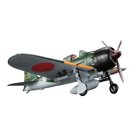
  9. Agora Models Mitsubishi A6M ZERO Fighter Manual

Agora Models Mitsubishi A6M ZERO Fighter Manual

STAGE 27: COCKPIT ASSEMBLY
STAGE 28: LEFT MAIN LANDING GEAR BASE
STAGE 29: LEFT MAIN LANDING GEAR BASE
AND WHEEL
STAGE 30: ASSEMBLING THE LEFT MAIN
LANDING GEAR (1)
STAGE 31: ASSEMBLING THE LEFT MAIN
LANDING GEAR (2)
STAGE 32: ASSEMBLING THE LEFT WING
STAGE 33: ATTACHING A TYPE 99 CANNON TO
THE WING
STAGE 34: INSTALLING THE LEFT MAIN MOTOR
STAGE 35: ASSSEMBLING THE MAIN COVERS
STAGE 36: ATTACHING THE LANDING GEAR
COVERS
Pack 04 |Build Instructions
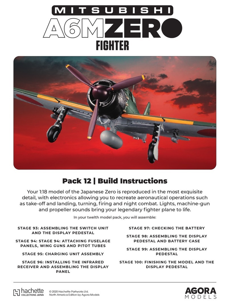
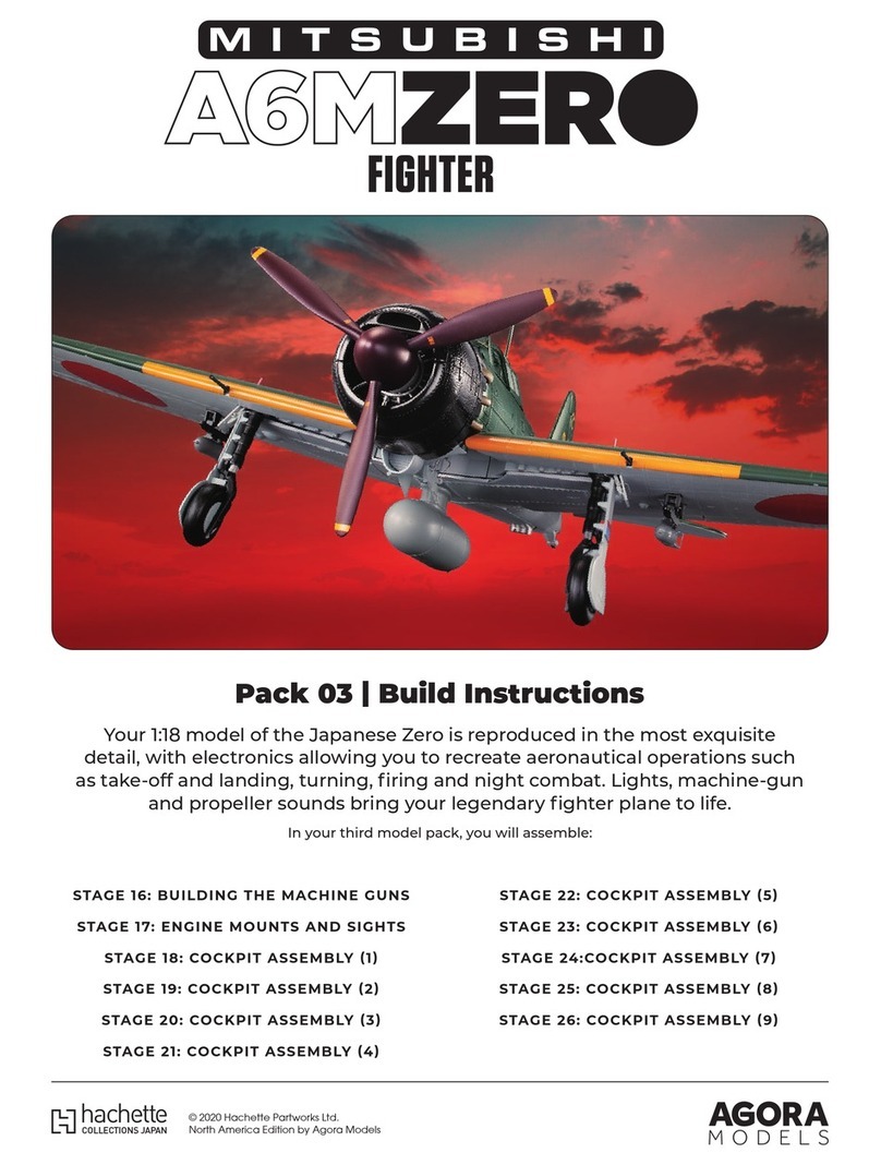
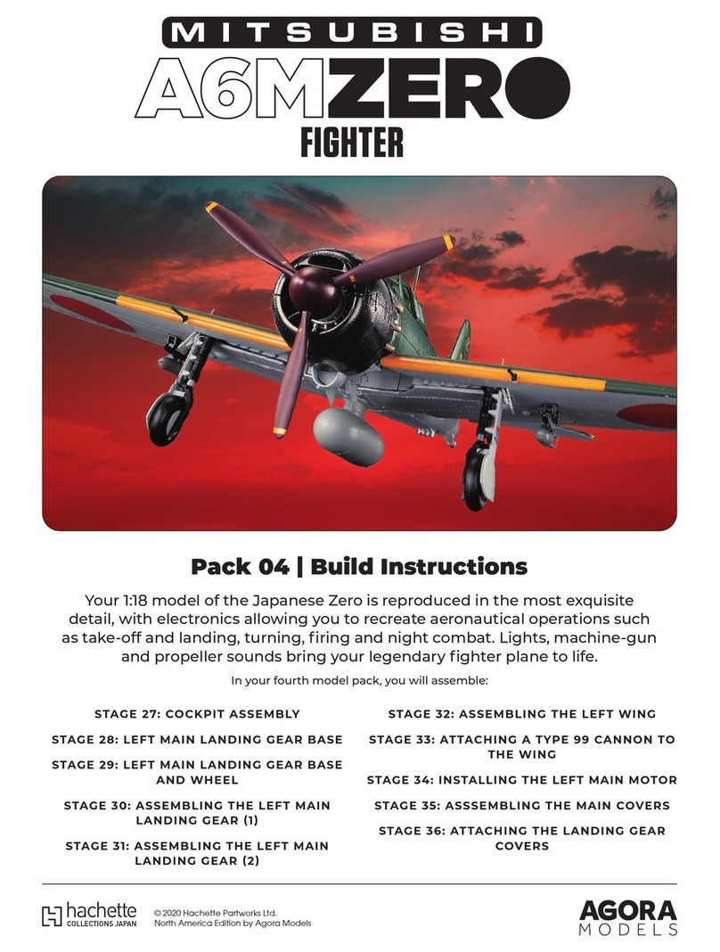
Your 1:18 model of the Japanese Zero is reproduced in the most exquisite
detail, with electronics allowing you to recreate aeronautical operations such
as take-off and landing, turning, firing and night combat. Lights, machine-gun
and propeller sounds bring your legendary fighter plane to life.
In your fourth model pack, you will assemble:
© 2020 Hachette Partworks Ltd.
North America Edition by Agora Models
2
AGORAMODELS A6M ZERO
Not suitable for children under the age of 14. This product is not a toy and is not designed for use in play. Keep
the parts out of the reach of small children. Some parts may have sharp edges. Please handle them with care.
Advice from the experts
Spare screws are included with each part. Occasionally, you may
be instructed to keep spare or unused screws for a later stage.
Keep these spares in a safe place and label them correctly.
Please make sure you don’t mix up the screws. They look quite
similar, but the threads do vary slightly. Using the wrong screws
may damage the parts.
When securing parts together using multiple screws, fit each
screw loosely to ensure all the parts are correctly aligned before
gently tightening them firmly, but not overtight, in the order in
which you placed them.
The screwdriver can be magnetised by stroking it with a magnet
(fridge magnet, etc.) enabling it to hold the screws and make
assembly easier.
If a screw is tight going into a metal part, do not force it as you
may shear the head off. Remove it and put a tiny smear of Vaseline,
soap or light oil on the thread. That will lubricate it and make it
easier to drive home.
During the course of this build, you will receive many pieces that
you will assemble immediately – following the instructions in the
corresponding stage – and other pieces that you should store
safely to one side, for use in future assembly stages.
When gluing parts together, glue may be applied to either of the
two parts. Some experts find it asier to apply glue to a hole rather
than a pin. Choose a method that works best for you.
It's a good idea to test fit your parts so that you can check their
positioning before gluing.
There are excellent videos showing
how to build the Zero here.
You will also need: superglue, small dish of water, tissue, cotton bud, tweezers
027-03
027-01 027-02
027-01
027-02
027-03
1
1
1
ABS resin
ABS resin
Die-cast
Decal
MATERIALNo.PART
STAGE 27 PARTS PARTS LIST
Stage 27 Assembly
Cockpit
In this stage, you will add a
decal to the instrument panel,
attach the seat and seat
adjustment lever to the cockpit
partition and complete the
cockpit.
Stage 27: Cockpit
assembly
組み立てガイド組み立てガイド
3
AGORAMODELS A6M ZERO
STEP 1
STEP 2
Insert the protrusions of seat 027-02 into the holes on the seat frames 026-03 & 026-04 assembled in stage 26, and glue the lower
lugs into the cockpit partition. Then glue the seat adjustment lever 027-01 to the cockpit partition.
Glue the two lugs on the instrument panel completed in STEP 1 to the two holes on the
left side frame of the cockpit.
STEP 3
NOTE
Push the two lugs on the instrument
panel (circled right) into the two holes
in the left cockpit frame (circled left).
019-02
021-02
2
Attach decal 027-03 to the instrument panel
assembled in stage 21. Prepare a small dish
of water, a tissue, and cotton bud.
Float the decal 027-03 in the dish of water
with the printed side facing up and wait
for about 10 seconds.
Remove the decal from the water using
tweezers and place it on a tissue to absorb
excess water.
Slide the decal with your finger and grab the part that comes off
the mount with tweezers. If it’s difficult to slide, the glue hasn’t
melted, so put it in water for a few seconds and try again.
Fine-tune the position with a cotton bud so that the compass is in the centre of the decal circle, and absorb excess water.
Attach decal 027-03 to the compass in the centre of the instru-
ment panel.
1 2 3
4 5
6
1
1
Glue the three tabs on the left side frame assembled in stage 25 to the three corresponding notches on the cockpit floor.
026-02
018-01
024-01
027-01
027-02
026-02
026-03026-04
027-03
:Glue
:Don’t Glue
組み立てガイド組み立てガイド
4
AGORAMODELS A6M ZERO
STEP 1 STEP 2
Insert the protrusions of seat 027-02 into the holes on the seat frames 026-03 & 026-04 assembled in stage 26, and glue the lower
lugs into the cockpit partition. Then glue the seat adjustment lever 027-01 to the cockpit partition.
Glue the two lugs on the instrument panel completed in STEP 1 to the two holes on the
left side frame of the cockpit.
STEP 3
NOTE
Push the two lugs on the instrument
panel (circled right) into the two holes
in the left cockpit frame (circled left).
019-02
021-02
2
Attach decal 027-03 to the instrument panel
assembled in stage 21. Prepare a small dish
of water, a tissue, and cotton bud.
Float the decal 027-03 in the dish of water
with the printed side facing up and wait
for about 10 seconds.
Remove the decal from the water using
tweezers and place it on a tissue to absorb
excess water.
Slide the decal with your finger and grab the part that comes off
the mount with tweezers. If it’s difficult to slide, the glue hasn’t
melted, so put it in water for a few seconds and try again.
Fine-tune the position with a cotton bud so that the compass is in the centre of the decal circle, and absorb excess water.
Attach decal 027-03 to the compass in the centre of the instru-
ment panel.
1 2 3
4 5
6
1
1
Glue the three tabs on the left side frame assembled in stage 25 to the three corresponding notches on the cockpit floor.
026-02
018-01
024-01
027-01
027-02
026-02
026-03026-04
027-03
:Glue
:Don’t Glue
組み立てガイド組み立てガイド
5
AGORAMODELS A6M ZERO
 
STEP 4
STEP 5
3
4
1 2
3
5
1
6
4
Glue the three tabs on the right side frame assembled in stage 24 to the three notches on the cockpit floor, and glue the two lugs on
the instrument panel into the two holes on the right side frame.
Align and glue the holes in the cockpit partition assembled in STEP 2 to the two protrusions on each of the left and right side frames. A
little extra glue can be applied to adjoining surfaces in 1–4 . Our video series shows you how and demonstrates the gluing technique.
Fix the partition wall assembled in stage 19 to the cockpit using the two screws 019-03 that came with stage 19. The machine guns fit
into the semi-circular notches at the top of the partition.
Pass the cord of the cockpit interior light 023-04 on the right
side of the cockpit through the groove on the outside of the
frame on the right side of the cockpit.
Pull the tip of the cockpit-light wire forward through the hole under
the 7.7mm machine gun magazine.
Insert the connector labelled B1 into the second socket from the
left on the board of the 7.7mm machine gun magazine.
Pull the tip of the cockpit-light wire forward through the hole under
the 7.7mm machine gun magazine.
Insert the connector labeled B2 into the second socket from the
right on the board of the 7.7mm machine gun magazine.
Pass the wire of the left interior light 025-04 through the groove
on the outside of the frame on the left side of the cockpit.
022-01
019-01
019-01
026-02
019-03
Click here to watch.
組み立てガイド組み立てガイド
6
AGORAMODELS A6M ZERO
 
STEP 4
STEP 5
3
4
1 2
3
5
1
6
4
Glue the three tabs on the right side frame assembled in stage 24 to the three notches on the cockpit floor, and glue the two lugs on
the instrument panel into the two holes on the right side frame.
Align and glue the holes in the cockpit partition assembled in STEP 2 to the two protrusions on each of the left and right side frames. A
little extra glue can be applied to adjoining surfaces in 1–4 . Our video series shows you how and demonstrates the gluing technique.
Fix the partition wall assembled in stage 19 to the cockpit using the two screws 019-03 that came with stage 19. The machine guns fit
into the semi-circular notches at the top of the partition.
Pass the cord of the cockpit interior light 023-04 on the right
side of the cockpit through the groove on the outside of the
frame on the right side of the cockpit.
Pull the tip of the cockpit-light wire forward through the hole under
the 7.7mm machine gun magazine.
Insert the connector labelled B1 into the second socket from the
left on the board of the 7.7mm machine gun magazine.
Pull the tip of the cockpit-light wire forward through the hole under
the 7.7mm machine gun magazine.
Insert the connector labeled B2 into the second socket from the
right on the board of the 7.7mm machine gun magazine.
Pass the wire of the left interior light 025-04 through the groove
on the outside of the frame on the left side of the cockpit.
022-01
019-01
019-01
026-02
019-03
組み立てガイド組み立てガイド
7
AGORAMODELS A6M ZERO
Fit the oil tank 020-03 that came with stage 20 into the partition wall. It does not glue.
Align the pins on the engine mount frame assembled in stage 17 with the four holes on the partition wall and glue them together.
2
3
020-03
019-01
STAGE COMPLETE
組み立てガイド組み立てガイド
8
AGORAMODELS A6M ZERO
You will also need: tweezers
028-01
028-02
028-05
028-08
028-04
028-03
028-06
028-09
028-07
028-01
028-02
028-03
028-04
028-05
028-06
028-07
028-08
028-09
ABS resin
ABS resin
ABS resin
ABS resin
ABS resin
ABS resin
Steel
Plastic
Plastic
1
1
1
1
1
1
1
1
1
MATERIALNo.PART
STAGE 28 PARTS PARTS LIST
Stage 28 Assembly
Left main landing gear base In this stage you will assemble the
base of the left main landing gear.
Stage 28: Left Main
Landing Gear Base
組み立てガイド組み立てガイド
9
AGORAMODELS A6M ZERO
NOTE
STEP 1
1 2
3
4
5
Align the pin on the leg position pointer 028-08 with the
groove on the shaft retainer 028-03.
Fit the gears 028-09 onto the shaft of the shock absorber 028-01.Fit the bearing 028-07 onto the shaft of the shock absorber 028-01
Fit part 028-04 onto the shock absorber 028-01, keeping the shock absorber in a horizontal position.
Push 028-02 onto the lug on 028-03 so that the leg position pointer 028-08 does not come off but can still slide within the groove.
Insert the leg position pointer 028-08 into the shaft retainer 028-03.
028-09
028-04
028-01
028-03
028-03
028-02
028-03
028-08
028-02
028-08
028-07
028-08
:Glue
:Don’t Glue
組み立てガイド組み立てガイド
10
AGORAMODELS A6M ZERO
NOTE
STEP 1
1 2
3
4
5
Align the pin on the leg position pointer 028-08 with the
groove on the shaft retainer 028-03.
Fit the gears 028-09 onto the shaft of the shock absorber 028-01.Fit the bearing 028-07 onto the shaft of the shock absorber 028-01
Fit part 028-04 onto the shock absorber 028-01, keeping the shock absorber in a horizontal position. Push 028-02 onto the lug on 028-03 so that the leg position pointer 028-08 does not come off but can still slide within the groove.
Insert the leg position pointer 028-08 into the shaft retainer 028-03.
028-09
028-04
028-01
028-03
028-03
028-02
028-03
028-08
028-02
028-08
028-07
028-08
:Glue
:Don’t Glue
組み立てガイド組み立てガイド
11
AGORAMODELS A6M ZERO
6
7
8
NOTE
Keep the leg position pointer 028-08 in the lowest
position when fitting.
Fit 028-03 assembled in 5 onto 028-04 assembled in 3. Work with the shock absorber 028-01 in the horizontal position.
Spread the metal fittings attached to the centre of the main landing gear cover 028-06 and fit them into the holes on the shock
absorber 028-01. Next, fit the metal fitting attached to the end of the main landing gear cover 028-06 into the L-shaped grooves on
the shaft retainer 028-03.
Fit the metal fitting holder 028-05 being careful not to move the metal fittings on the main landing gear cover.
028-05
028-03
028-06
028-01
028-04
028-03
028-01
STAGE COMPLETE
組み立てガイド組み立てガイド
12
AGORAMODELS A6M ZERO
6
7
8
NOTE
Keep the leg position pointer 028-08 in the lowest
position when fitting.
Fit 028-03 assembled in 5 onto 028-04 assembled in 3. Work with the shock absorber 028-01 in the horizontal position.
Spread the metal fittings attached to the centre of the main landing gear cover 028-06 and fit them into the holes on the shock
absorber 028-01. Next, fit the metal fitting attached to the end of the main landing gear cover 028-06 into the L-shaped grooves on
the shaft retainer 028-03.
Fit the metal fitting holder 028-05 being careful not to move the metal fittings on the main landing gear cover.
028-05
028-03
028-06
028-01
028-04
028-03
028-01
STAGE COMPLETE
組み立てガイド組み立てガイド
13
AGORAMODELS A6M ZERO
You will also need: tweezers
*029-04 will not be used in this stage. Keep it in a safe place until required.
029-01 029-02 029-03
029-04 029-05 029-06
029-01
029-02
029-03
029-04
029-05
029-06
Steel
Plastic
PVC
ABS resin
ABS resin
ABS resin
1
1
1
1
1
1
MATERIALNo.PART
STAGE 29 PARTS PARTS LIST
Stage 29 Assembly
Landing gear base and wheel
In stage 29, gears will be installed in the
base of the left main landing gear
assembled in stage 28, and a wheel will
also be assembled.
Stage 29: Assembling the
Left Main Landing Gear
Base and Wheel
組み立てガイド組み立てガイド
14
AGORAMODELS A6M ZERO
STEP 1 STEP 2
1
2
1
2
Fit the bearing 029-01 onto the shaft of the shock absorber assembly from stage 28.
Fit gear 029-02 onto the shaft of the shock absorber.
Fit and glue wheel parts 029-05 and 029-06.
Fit the tyre 029-03 to the wheel assembled in 1, pulling and tucking the centre ring into the grooves on the wheel.
029-01
029-06
029-05
029-03
029-05
029-02
STAGE COMPLETE
:Glue
:Don’t Glue
組み立てガイド組み立てガイド
15
AGORAMODELS A6M ZERO
STEP 1
STEP 2
1
2
1
2
Fit the bearing 029-01 onto the shaft of the shock absorber assembly from stage 28.
Fit gear 029-02 onto the shaft of the shock absorber.
Fit and glue wheel parts 029-05 and 029-06.
Fit the tyre 029-03 to the wheel assembled in 1, pulling and tucking the centre ring into the grooves on the wheel.
029-01
029-06
029-05
029-03
029-05
029-02
STAGE COMPLETE
:Glue
:Don’t Glue
組み立てガイド組み立てガイド
16
AGORAMODELS A6M ZERO
You will also need: superglue, tweezers.
030-03
030-06
030-01
030-02
030-07
030-04 030-05
030-08 030-09 030-10
030-01
030-02
030-03
030-04
030-05
030-06
030-07
030-08
030-09
030-10
Die-cast
ABS resin
ABS resin
ABS resin
ABS resin
ABS resin
Steel
Steel
Steel
Steel
1
1
1
1
1
1
1
1
1
1
MATERIALNo.PART
STAGE 30 PARTS PARTS LIST
Stage 30 Assembly
Left Main Landing Gear
This stage includes a mechanism built into
the main landing gear support to absorb the
impact during landing.
Stage 30: Assembling the
Left Main Landing Gear (1)
組み立てガイド組み立てガイド
17
AGORAMODELS A6M ZERO
STEP 1
030-01
030-01
030-05
030-02
030-01
030-06
030-10
030-05
030-04
030-04
030-09
030-07
030-08
030-08
NOTE
Insert the left main landing gear support 030-01 into the spring
030-07.
Insert the support assembled in 1 into the base of the left main
landing gear assembled in stage 29.
Push the parts together, and insert the pin 030-08 into the hole in the base of the left main landing gear.
If the pin 030-08 is inserted into the groove on the left main
landing gear support 030-01 the support will not come off.
Insert the pin 030-08 with the smooth end first. Push until
the pin is completely inside the hole.
Combine the lower arm 030-04 and the upper arm 030-05 and fix them with pin 030-09.
Fit the holes on the upper arm 030-05 onto the tip of the left main
landing gear base, and insert the pin 030-10 to secure it in place.
Insert the lugs on the lower arm 030-04 of the arm assembled in
4 into the holes on the left main landing gear support 030-01.
Glue the lugs on the brake line 030-02 to the two holes in the left main landing gear base cover 030-06.
7
1
3
2
4
5 6
:Glue
:Don’t Glue
組み立てガイド組み立てガイド
18
AGORAMODELS A6M ZERO
STEP 1
030-01
030-01
030-05
030-02
030-01
030-06
030-10
030-05
030-04
030-04
030-09
030-07
030-08
030-08
NOTE
Insert the left main landing gear support 030-01 into the spring
030-07.
Insert the support assembled in 1 into the base of the left main
landing gear assembled in stage 29.
Push the parts together, and insert the pin 030-08 into the hole in the base of the left main landing gear.
If the pin 030-08 is inserted into the groove on the left main
landing gear support 030-01 the support will not come off.
Insert the pin 030-08 with the smooth end first. Push until
the pin is completely inside the hole.
Combine the lower arm 030-04 and the upper arm 030-05 and fix them with pin 030-09.
Fit the holes on the upper arm 030-05 onto the tip of the left main
landing gear base, and insert the pin 030-10 to secure it in place.
Insert the lugs on the lower arm 030-04 of the arm assembled in
4 into the holes on the left main landing gear support 030-01.
Glue the lugs on the brake line 030-02 to the two holes in the left main landing gear base cover 030-06.
7
1
3
2
4
5 6
:Glue
:Don’t Glue
組み立てガイド組み立てガイド
19
AGORAMODELS A6M ZERO
030-06
030-03
030-03
029-04
030-06
Glue the 6 lugs on the left main landing gear base cover 030-06 assembled in 7 to the left main landing gear base. Note that the
brake line runs on the outside of the third pair of lugs.
Glue the left brake disc 030-03 to the left main landing gear
support 030-01, and insert the tip of the brake line 030-02 into
the hole on 030-03.
Fit the wheel assembled in stage 29 onto the left brake disc
030-03. Do not glue.
Glue the lugs on the left tyre cover 029-04 to the hole in the left
main landing gear support. Be careful not to glue it to the left
main landing gear base cover 030-06.
8
910
11 STAGE COMPLETE
組み立てガイド組み立てガイド
20
AGORAMODELS A6M ZERO

Other manuals for Mitsubishi A6M ZERO Fighter

5

Other Agora Models Toy manuals

Agora Models Bismarck Manual

Agora Models

Agora Models Bismarck Manual

Agora Models FERRARI 312 T4 User manual

Agora Models

Agora Models FERRARI 312 T4 User manual

Agora Models FERRARI 312 T4 User manual

Agora Models

Agora Models FERRARI 312 T4 User manual

Agora Models OPTIMUS PRIME Manual

Agora Models

Agora Models OPTIMUS PRIME Manual

Agora Models Mitsubishi A6M ZERO Fighter Manual

Agora Models

Agora Models Mitsubishi A6M ZERO Fighter Manual

Agora Models Hachette Mitsubishi A6MZERO FIGHTER Manual

Agora Models

Agora Models Hachette Mitsubishi A6MZERO FIGHTER Manual

Agora Models OPTIMUS PRIME Pack 04 Manual

Agora Models

Agora Models OPTIMUS PRIME Pack 04 Manual

Agora Models ALIEN Pack 03 Manual

Agora Models

Agora Models ALIEN Pack 03 Manual

Agora Models OPTIMUS PRIME Pack 05 Manual

Agora Models

Agora Models OPTIMUS PRIME Pack 05 Manual

Agora Models OPTIMUS PRIME Pack 03 Manual

Agora Models

Agora Models OPTIMUS PRIME Pack 03 Manual

Agora Models Bismarck 06 Manual

Agora Models

Agora Models Bismarck 06 Manual

Agora Models ALIEN Pack 04 Manual

Agora Models

Agora Models ALIEN Pack 04 Manual

Agora Models LONDON TRANSPORT ROUTEMASTER RM 857 Manual

Agora Models

Agora Models LONDON TRANSPORT ROUTEMASTER RM 857 Manual

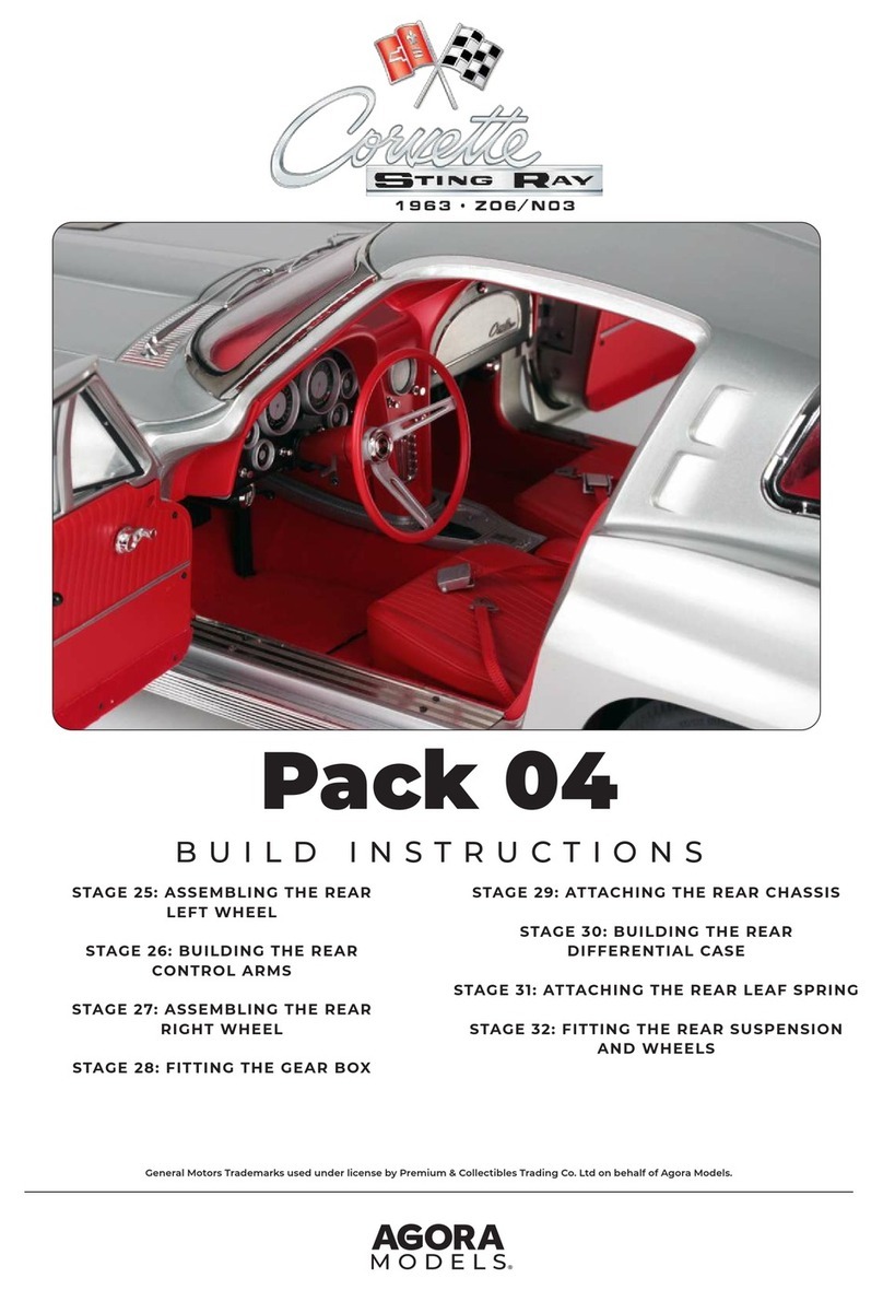
Agora Models CORVETTE STING RAY 1963-Z06/N03 Manual

Agora Models

Agora Models CORVETTE STING RAY 1963-Z06/N03 Manual

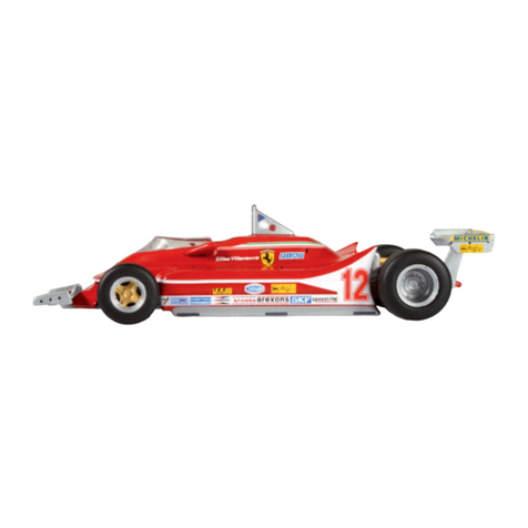
Agora Models FERRARI 312 T4 User manual
Agora Models

Agora Models FERRARI 312 T4 User manual

Agora Models Mitsubishi A6M ZERO Fighter Manual

Agora Models

Agora Models Mitsubishi A6M ZERO Fighter Manual
Agora Models Mitsubishi A6M ZERO Fighter Manual

Agora Models

Agora Models Mitsubishi A6M ZERO Fighter Manual

Agora Models OPTIMUS PRIME Pack 02 Manual
Agora Models

Agora Models OPTIMUS PRIME Pack 02 Manual

Agora Models Hachette Mitsubishi A6MZERO FIGHTER Manual

Agora Models

Agora Models Hachette Mitsubishi A6MZERO FIGHTER Manual

Agora Models FDNY FIRE TRUCK TOWER LADDER 9 Manual

Agora Models

Agora Models FDNY FIRE TRUCK TOWER LADDER 9 Manual

Agora Models Mitsubishi A6M ZERO Fighter Manual

Agora Models

Agora Models Mitsubishi A6M ZERO Fighter Manual

Agora Models OPTIMUS PRIME Pack 01 Manual

Agora Models

Agora Models OPTIMUS PRIME Pack 01 Manual

Agora Models Hachette Mitsubishi A6MZERO FIGHTER Manual

Agora Models

Agora Models Hachette Mitsubishi A6MZERO FIGHTER Manual

Agora Models ALIEN Manual

Agora Models

Agora Models ALIEN Manual

Popular Toy manuals by other brands

LEGO Bionicle 70781 Assembly guide

LEGO

LEGO Bionicle 70781 Assembly guide

Chad Valley 557-8025 Assembly & user instructions

Chad Valley

Chad Valley 557-8025 Assembly & user instructions

Electrovision GH916 manual

Electrovision

Electrovision GH916 manual

Educational Insights EI-4112 manual

Educational Insights

Educational Insights EI-4112 manual

Hasbro Beyblade Metal Driger 82656 instructions

Hasbro

Hasbro Beyblade Metal Driger 82656 instructions

Fisher-Price SERGEANT SIRENTM G6534 instruction sheet

Fisher-Price

Fisher-Price SERGEANT SIRENTM G6534 instruction sheet

marklin BR 261 DB manual

marklin

marklin BR 261 DB manual

LEGO Ninjago 70505 Building instructions

LEGO

LEGO Ninjago 70505 Building instructions

The World Models Manufacturing Rambler EP instruction manual

The World Models Manufacturing

The World Models Manufacturing Rambler EP instruction manual

BRAWA Locomotive E 42 operating instructions

BRAWA

BRAWA Locomotive E 42 operating instructions

Mattel little MOMMY Bake with Me Baby instructions

Mattel

Mattel little MOMMY Bake with Me Baby instructions

Eduard BAC Lightning F.1A/ F.3 interior S.A. manual

Eduard

Eduard BAC Lightning F.1A/ F.3 interior S.A. manual

Dancing Wings Hobby K13 Beechcraft T-34 Mentor instruction manual

Dancing Wings Hobby

Dancing Wings Hobby K13 Beechcraft T-34 Mentor instruction manual

Mattel MOJANG instructions

Mattel

Mattel MOJANG instructions

LEGO CREATOR 10233 Building instructions

LEGO

LEGO CREATOR 10233 Building instructions

EBMA Hobby & Craft Wing Jig Construction Instructions

EBMA Hobby & Craft

EBMA Hobby & Craft Wing Jig Construction Instructions

LGB 20990 manual

LGB

LGB 20990 manual

Educational Insights CoinStruction EI-4026 Helicopter manual

Educational Insights

Educational Insights CoinStruction EI-4026 Helicopter manual

manuals.online logo
manuals.online logoBrands
  • About & Mission
  • Contact us
  • Privacy Policy
  • Terms and Conditions

Copyright 2025 Manuals.Online. All Rights Reserved.