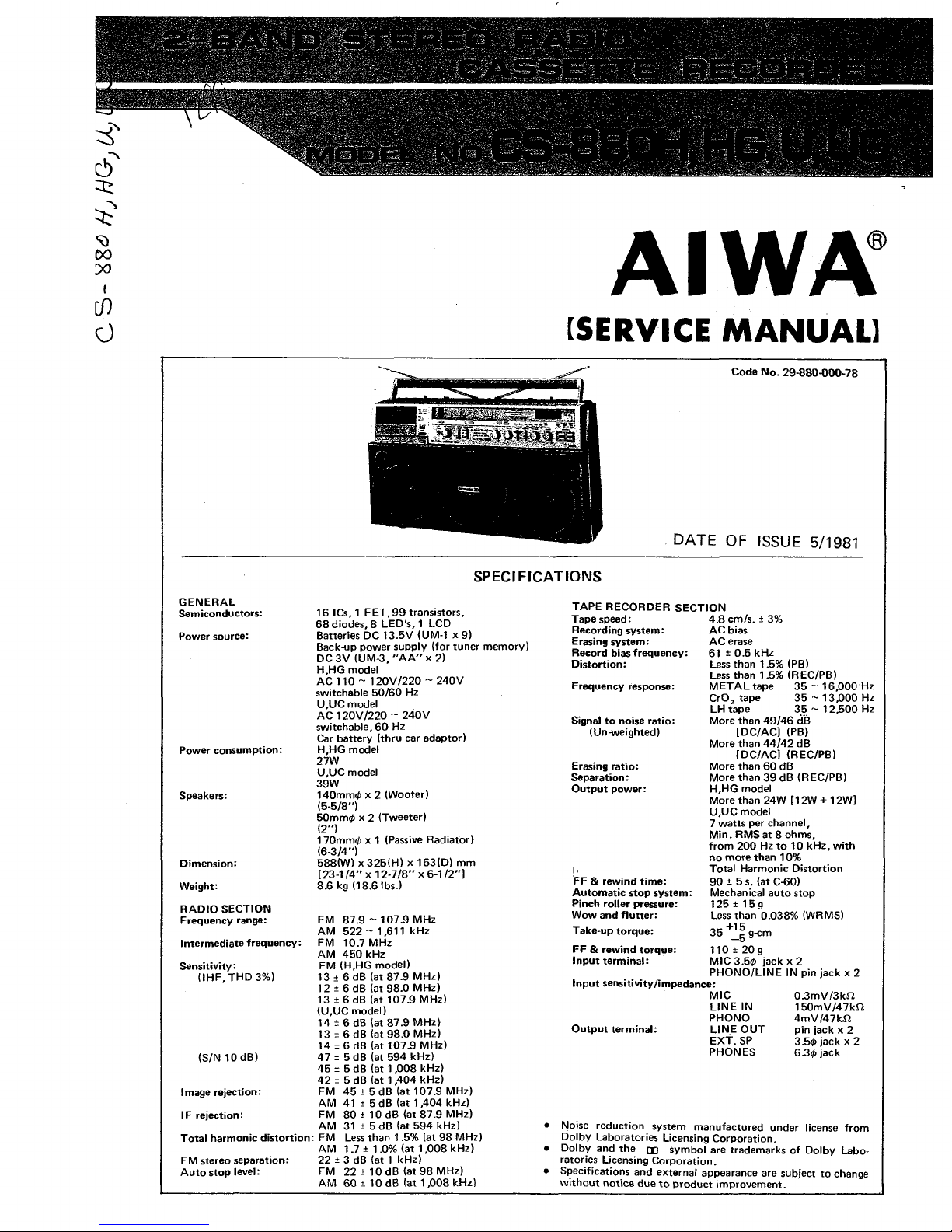
Aiwa CS-880 H User manual

G S- H
à
's AIWA
[SERVICE MANUAL]
Code No. 29-880-000-78
DATE OF ISSUE 5/1981
SPECIFICATIONS
GENERAL
Se iconductors:
Power source:
Power consu ption:
Speakers:
Di ension:
Weight:
RADIO SECTION
Frequency range:
Inter ediate frequency:
Sensitivity:
(IH F, THD 3%)
16 ICs, 1 FET.99 transistors,
68 diodes, 8 LED's, 1 LCD
Batteries DC 13.5V (UM-1 x 9)
Back-up power supply (for tuner e ory)
DC 3V (UM-3, "A A "x 2)
H,HG odel
AC 110 ~ 120V/220 ~ 240V
switchable 50/60 Hz
U,UC odel
AC 120V/220 ~ 240V
switchable, 60 Hz
Car battery (thru car adaptor)
H,HG odel
27W
U,UC odel
39W
14O 0 x 2 (Woofer)
(5-5/8")
5O 0 x 2 (Tweeter)
(2")
17O 0 x 1 (Passive Radiator)
(6-3/4” )
588(W) x 325(H) x 163(D)
[23-1/4" x 12-7/8" x 6-1/2")
8.6 kg (18.6 lbs.)
FM
AM
FM
AM
875 ~ 107.9 MHz
522 ~1,611 kHz
10.7 MHz
450 kHz
FM (H,HG odel)
13 ± 6 dB (at 87.9 MHz)
12 ± 6 dB (at 98.0 MHz)
13 ± 6 dB (at 107.9 MHz)
(U,UC odel)
14 ±6 dB (at 87.9 MHz)
13 +6 dB (at 98.0 MHz)
14 ±6 dB (at 107.9 MHz)
(S/N 10 dB) 47 ±5 dB (at 594 kHz)
45 ±5 dB (at 1,008 kHz)
42 ±5 dB (at 1,404 kHz)
I age rejection: FM 45 ±5 dB (at 107.9 MHz)
AM 41 ±5 dB (at 1,404 kHz)
IF rejection: FM 80 ±10 dB (at 87.9 MHz)
AM 31 +5 dB lat 594 kHz)
Total har onic distortion:: FM Less than 1.5% (at 98 MHz)
AM 1.7 ±1.0% (at 1,008 kHz)
FM stereo separation: 22 ±3 dB (at 1 kHz)
Auto stop level: FM 22 ±10 dB (at 98 MHz)
AM 60 ±10 dB (at 1,008 kHz)
TAPE RECORDER SECTION
Tape speed: 4.8 c /s. ± 3%
Recording syste :
Erasing syste :
Record bias frequency:
Distortion:
Frequency response:
Signal to noise ratio:
(Un-weighted)
Erasing ratio:
Separation:
Output power:
IFF & rewind ti e:
Auto atic stop syste :
Pinch roller pressure:
Wow and flutter:
Take-up torque:
AC bias
AC erase
61 ± 0.5 kHz
Less than 1.5% (PB)
Less than 1.5% (REC/PB)
M ETALtape 35- 16,000 Hz
CrOj tape 35 ~ 13,000 Hz
LH tape 35 ~ 12,500 Hz
More than 49/46 dB
[DC/AC] (PB)
More than 44/42 dB
[DC/AC] (REC/PB)
More than 60 dB
More than 39 dB (REC/PB)
H,HG odel
More than 24W [12W + 12W)
U,UC odel
7 watts per channel,
Min. RMS at 8 oh s,
fro 200 Hz to 10 kHz, with
no ore than 10%
Total Har onic Distortion
90 ±5 s. (atC-60)
Mechanical auto stop
125 ± 15q
Less than 0.038% (WRMS)
, , +15
35 c g-c
FF & rewind torque:
Input ter inal:
-5
110 ± 20g
MIC 3.50 jack x 2
PHONO/LINE IN pin jack x 2
Input sensitivity /i pedance:
MIC 0.3 V/3kfi
LIN E IN 150 V/47kn
PHONO 4 V/47kii
Output ter inal: LIN E OUT pin jack x 2
EXT. SP 3.50 jack x 2
PHONES 6.30 jack
Noise reduction syste anufactured under license fro
Dolby Laboratories Licensing Corporation.
Dolby and the [Xj sy bol are trade arks of Dolby Labo
ratories Licensing Corporation.
Specifications and external appearance are subject to change
without notice due to product i prove ent.

CS-880H,HG,U,UC L AIWA
DISASSEMBLING CHART OF MAIN PARTS
To avoid troubles when disasse bling or replacing the ain parts, follow the chart diagra as below.
Radio chassis
(Including radio chassis, tuning, display MS, Af|
{pattern side) PC Boards)
Tuning circuit board
A F circuit board (Part side) i
MD-3 echanis
2

AIWA J CS-880H,HG,U,UC
DISASSEMBLY INSTRUCTIONS
Removing the Main Case
1) Re ove 11 screws on the rear lid shown by arrows <
- Q © o
________
j—
-----
-
rO§"©On
-
-
°v=Cj -
— Ö 1- ©<= ”
-
“□
Installing the Main Case
1) Check that the fibre apper of the REC/PB PC Board (pattern
die) is fixed properly.
Fir ly fix the fibre paper using two-sided tape, etc.
because it is likely to lift up when it is peeled off
once.
2) Lower all the lever switches in the direction of the arrow.
2) Re ove 9 knobs. 5 0 3 ) Be sure to install in the order (1) — (3). Be careful: when
it is ounted incorrectly, it ay da age the dial plate
and the display PC Boards, etc.
S g 3 ) Open the cassette lid.
(It is not required to re ove the cassette lid) 4) Match the knobs while perfor ing ite 3) and tapping the
side.
3

CS-880H,HG,U,UC
JL
AIWA
Re oving the radio chassis
1) Be sure to re ove the level eter before starting work to
prevent the pointer of the level eter fro being da aged.
Installing the radio chassis
1) Hook the jack plate to the tab of the rear lid while paying
attention not to pinch the wire. Co press the radio chassis
against the direction of the arrow after checking that the
tuner PC Board is inserted into the rib.
4

AIWA I CS-880H,HG,U;UC
Removing Mechanism
1) Loosen the screw and re ove the hook of the rod. 2) Re ove 4 screws.
5

CS-880H,HG,U,UC 1 AIWA
Cautions on Disassembling MD-3 Mechanism
Disasse ble or repair the MD-3 echanis while paying attention
to the springs and levers, etc. shown in the figure below.
the lever R EC driver)
Be sure to hook the T-spring (PLA Y lever) to the ca of the
gear when installing the gear PLA Y.
Hook it fro the inside of the gear using a clock screwdriver
as shown in the figure. Perfor the sa e for the gear FR
and ca gear PAU SE.
6

AIWA
J
CS-880H,HG,U,UC
DESCRIPTION OF THE MD-3 MECHANISM
Description of the PL Y Operation
With the plate button pressed, the trigger lever (PLA Y) oves in
the direction of the arrow «- (1), the gear (P LA Y) is released fro
the boss of the trigger lever (P LAY) engages with the gear flywheel
and rotates in the direction of the arrow ■*- (2), the boss (A) of the
gear (P LA Y) touches the trigger lever (PLA Y) and the gear
stops rotating.
When the gear (PLA Y ) rotates, the lever (PLA Y) oves in the
direction of the arrow •*- (3) along the ca groove on the rear of
the gear to push up the operation chassis in the direction of the
arrow <-(4). **
The PLA Y button which has been locked is released by pressing
the STOP button, the trigger lever (PLA Y) oves in the direction of
the arrow *- (5), the boss (A) of the gear (PLA Ÿ) is released and the
PLA Y operation stops.
the boss (A ) of the gear (PLA Y).

CS-880H,HG,U,UC JAIWA
Description of the FF Operation
When the FF button is pressed, the trigger lever FF oves in the
direction of the arrow *- (1 ), the boss of the gear FR ca is released
and engages with the gear wheel to rotate in the direction of the
arrow <- (2), the boss (A) touches the boss of the trigger lever FF
and the gear FR ca stops. The FR lever B oves in the direction
of the arrow <- (3) along the groove of the gear FR ca , the FR
lever B oves in the direction of the arrow «- (3), the FR lever C
co presses the gear of the FR lever A » 'y against the Take-up
reel disc ass'y to perfor the FF operation.
Boss A FR lever B
8

AIWA
J
[ CS-880H.HG.il.UC
REW Operation
When the REW button is pressed, the trigger lever REW oves in
the direction of the arrow <- (1) and pushes the lever REW in the
direction of the arrow <- (2). The trigger lever FF releases the boss
A of the gear at that ti e, the gear FR engages with the gear fly
wheel, rotates in the direction of the arrow <- (3), boss B touches
the trigger lever FF and rotation stops.
The FR gear B is oved in the dirSfction the arrow <- (4) by eans
of the ca of the gear FR following the rotation of the gear FR ;
pulls thè FR lever C in the direction of the arrow <- (5) and oves
the FR lever ass’y in the direction of the arrow ■*- (6) to rotate the
Take-up reel disc reel disc ass'y to perfor the REW operation.
9

CS-880H,H6,U,UC J I AIWA
Description of the P USE Operation
When the PA USE button is pressed, the trigger lever PAUSE oves
in the direction of the arrow +- (1), the boss A of the gear PA USE
is released, enages with the gear flywheel and rotates in the
direction of the arrow - (2), the boss B touches the trigger PAUSE
and rotation stops.
The PAU SE lever oves in the direction of the arrow *- (3) along
the ca groove of the PA USE g e^ a t that ti e. The PLA Y idler
lever and the pinch lever ass'y is oved to perfor the PAUSE
operation at that ti e.
When the PA USE button is pressed again, the button is released
fro locking and si ultaneously the boss B of the gear PA USE is
released fro the trigger lever PAU SE and the PA USE operation
Play idler lever Lever, PAU SE
10

AIWA
J
CS-880H,HG,U,UC
R EC Operation
When one of the STOP, FF and REW buttons is pressed, the REC
When the R EC and PLA Y buttons are pressed si ultaneously. trjgger |ever js re|eased fro the R Ê t ,ever driver and on|y the
the trigger lever R EC oves in the direction of the arrow - (1 ). REC operation is released.
The P LA Y operation is perfor ed si ultaneously at that ti e,
so the R EC lever driver oves in the direction of the arrow <-.(2),
pushes the lever R EC A, B in the direction of the arrow (3),
the interlocked slide REC plate pulls the rod, the slide switch is
11

CS-880H,HG,U,UC JIAIWA
Description of the uto-stop Operation
The otor rotation is trans itted to the gear auto-kick of the
MD-3 echanis via the slip pulley FR ass’y.
The slip disk presses the lever auto A in the direction of the arrow
<- (1) when the Take-up reel disc ass'y is rotating, so the boss of the
lever auto A oves along the ca (A ) groove of the gear auto-kick.
When the reel discs (S, T sides) stop, the lever auto A stops in the
condition being oves in the direction of flle arrow (2).
The ca (B) of the gear auto-kick oves the lever auto A in the
direction of the arrow <- (3), operates the plate auto-kick in the
direction of the arrow <- (4) to release the plate lock and perfor s
the AUTO STOP operation.
Boss
12

AIWA
J
CS-880H,HG,U,UC
SPRING APPLICATION POSITION
13

CS-880H,HG,U,UC j AIWA
E PLODED VIEW—1
1 I 2 3 I 4 I 5 7
B
H
14

AIWA j
MECHANICAL PARTS P RTS LIST
I
CS-880H,HG,U,UC
1 ark in this part list shows exclusive part.
Ref. No. Part No. Part No.
Changed to Description Common
odel Q'ty
1-1 a 09-017-839-01 Main case ass’y (Silver) *1
(H,U,UC odel only)
1-1b 09-017-840-01 Main case ass'y (Blue) *1
82-58 7-001-01 Cabinet, Main (Silver) * «• 1
82-587-044 -0 1 Cabinet, Main (Blue) •1
82-58 7-234-01 Da per A, Rubber •14
82-587-235 -0 1 Da per B, Rubber
8 2 -5 8 7 -0 0 7 -0 t Panching (Silver) *1
82-587-045-01 Panching (Blue) •1
82-58 7-036-01 Badge (Stiver) *1
82-587-060-01 Badge (Blue) •1
82-587-009 -0 1 Side panel R *1.
82-587-010-01 Side panel L *1
82-587-027 -0 1 Panel, Front •1
82 -5 63-032-01 Cassette plate CS-990 1
82-587-003 -0 1 Window, Dial *1
82-587-221-01 E-spring (tact) •1
82-587-040 -0 1 Label, DSL »1
82-587-239-01 P-sprin , T act A *
87-392-003 -0 1 Nut, Speed
87-321-097-21 Q T, + 3 - 1 2
1-2 82-587-635-01 Drone cone ass'y *1
1-3 82-587-227-01 P-spring, Earth •1
1-4 82-576-241-01 E-spring, Earth CS-350 1
1-5 82-587-020-01 T act push-key *12
1-6 82-587-021 -01 Push-button *
1-7 82-587-218-01 T-spring, Cassette lid *1
1-8 82-587-202-01 Cassette box *1
1-9a 82-587-004-01 Window, Cassette (Silver) *1
(H,U,UC odel only)
1-9b 82-587-047-01 Window, Cassette (Blue) *1
1-10 82-587-011-01 Decorative panel. Cassette *1
1-11 87-081-979-01 Decorative screw 3-12
1-12 82-587-219-01 P-spring, Cassette holder *
1-13a 09-017-841-01 Back cover ass'y (H,HG odel only) *1
1-13b 09-017-842-01 Back cover ass'y (U,UC odel only) ■ft 1
82-587-038-01 Back cover ass'y (H,HG m odel only) *1
82-587 -0 42-01 Back cover ass'y (U ,UC m odel only) 1
82-587-236-01 Rubber cushion 4-6-4
82-587 -2 13-01 C-sprin , Term inal A •1
82-587 -2 14-01 C-spring, Ter inal B *1
82-587 -2 16-01 C-spring, Ter inal C •1
82-587-215 -0 1 Term inal plate U, *1
82-587-217 -0 1 Ter inal plate U3 1
82-587-226 -0 1 Sheet, Faiber •
82-277 -3 82-01 Spring, Ter inal 1
81-235-211-01 Ter inal plate D 1
87-349-095-21 U T, + 3 - 8 1
1-14 82-534-203-01 Click plate spring R 1
1-15 82-587-212-01 Shaft, Handle *
1-16 82-587-231-01 Rubber bushing 6 x1 0 *1
1-17 82-587-233-01 Rubber bushing 7x10 *1
1-18 87-038-039-01 Wire binder
1-19 82-587-208-01 Rubber bushing 3 x 5 *1
1-20 82-587-013-01 Handle L * 1
1-21 82-587-014-01 Handle grip *1
1-22 82-587-012-01 Handle R »1
1-23 82-587-005-01 Battery roo lid * 1
1-24 82-587-237-01 M cushion 14 x 35 x 5 *1
1-25a 82-587-211-01 Cushion, Battery (H,HG odel only) *2
1-25b 82-588-223-01 M cushion 7 x 281 x 7 CS-770 2
1-26 82-587-017-01 Knob *4
1-27 82-563-014-01 Knob, TOG GLE CS-990 4
1-28 82-587-023-01 Knob, VOLU M E (UP) *1
1-29 82-587-024-01 Knob, VO LU ME (DOWN) *1
1-30a 82-587-029-01 Na e plate. Spec. (H odel only) *1
1-30b 82-587-033-01 Na e plate. Spec. (HG odel only) *1
1-30C 82-587-032-01 Na e plate. Spec. (U,UC odel only) *1
1-31a 82-587-025-01 AC jack plate (H,HG odel only) *1
1-31b 82-587-026-01 AC jack plate (U,UC odel only) *1
1-31C 82-587-034-01 AC jack plate S-1 (UC odel only) *1
1-31d 82-587-035-01 AC jack plate S-2 (U,UC odel only) *1
................
- ■ — ?

CS-880H,HG,uj u
E PLODED VIEW—2
1 I 2
B
H
16

AIWA
J
CS880H;HG,U,UC
Ref. No. Part No. Part No.
Changed to Description Co on
Model Q'ty
2-1 87-043-058-01 Whip antenna 2
2-2 87-033-166-01 Antenna ter inal 2
2-3 82-587-220-01 Ter inal plate. Antenna *2
2-4 82-587-205-01 Rod, REC •1
2-5 82-588-209-01 Cushion 15 x 15 x 41 CS-770 1
2-6 82-587-242-01 Sheet, Fiber A •2
2-7 82-587-211-01 Cushion, Battery *1
2-8 82-587-225-01 Rod 37.8 •1
2-9 82-587-206-01 Rod 87.8 *2
2-10 82-587-608-01 Shield, Front *1
2-11 82-587-238-01 Rubber cushion 10 x 25 x 14 •1
2-12 82-587-201-01 Chassis *1
2-13 82-587-207-01 Holder, Dial plate *2
2-14 82-162-037-01 Push-button B 2 ÀD-R500 H,U,UC:4
HG:3
2-15 82-588-634-01 Earth, REC CS-770 1
2-16a 82-587-008-01 Dial plate (Silver)
(H,U,UC odel only) *1
2-16b 82-587-061-01 Dial plate (Blue)
(H,HG odel only)
*1
2-16c 82-587-062-01 Dial plate (Blue)
(U,UC odel only)
*1
2-17 87-064-084-01 Holder , ECM 30 2
2-18 82-587-019-01 Push-key, REC ute *1
2-19 82-563-247-01 E-spring, Air-da p CS-990 1
2-20 87-096-045-01 String, Dial 1
2-21 87-078-003-01 Air-da p unit ass'y 1
2-22 82-587-240-01 LED reflector *1
2-23 82-587-224-01 Holder, Switch *1
2-24 87-040-143-01 Counter 1
2-25 82-587-209-01 Rubber belt *1
2-26 82-587-203-01 Holder, Counter *1
2-27 82-587-037-01 Push-key, REC *1
2-28 82-587-018-01 Push-key, Tape recorder *5
2-29 82-588-208-01 Rubber cushion 33-6-3 CS-770 1
2-30 87-063-113-01 Cushion WA 2
2-31 82-587-049-01 Push-button, DSL *1
17

CS-880H,HG,U,UC J[ AIWA
E PLODED V IE W —3
1 I 2
B
U 02-I2
H
PW I.7-3.5-0.25
PW I.7-3.5-0.25
PWI.7-3.5~0.25
18

AIWA
J
CS-880H,H6,U,UC
Ref. No. Part No. Part No.
Changed to Description Common
odel Q'ty
3-1 82-585-325-01 Outsert chassis 1
3-2 82-585-277-01 Plate button, F R 3
3-3 82-585-337-01 Plate button, REC 3
3-4 82-585-279-01 Lever A, Eject 1
3-5 82-585-255-01 REC blocking lever 1
3-6 82-585-319-01 P-spring, Cassette pressure 1
3-7 82-585-254-01 Slide plate. Eject 1
3-8 82-585-311-01 E-spring, Lid lock 1
3-9 82-585-290-01 C-spring, Back tension 1
3-10 82-585-215-01 Supply reel platfor ass'y 1
3-11 82-585-292-01 C-spring, Slip disk 1
3-12 82-585-272-01 Slip disk T 1
3-13 82-585-210-01 Take-up reel platfor ass'y 1
3-14 82-585-294-01 T-spring, Center shift 1
3-15 82-585-312-01 E-spring, Brake R 1
3-16 82-585-253-01 Lever, Brake R 1
3-17 82-585-286-01 Rubber cushion. Brake
3-18 82-585-252-01 Lever, Brake L 1
3-19 82-585-265-01 R EV lever 1
3-20 82-585-231-01 F R lever ass'y 1
3-21 82-585-235-01 Gear A, REW 1
3-22 82-585-223-01 Play idler lever ass’y 1
3-23 82-585-313-01 F-spring, Play idler 1
3-24 82-585-364-01 Pinch lever B ass'y 1
3-25 82-585-296-01 T-spring, Pinch lever 1
3-26 82-585-340-01 Plate lock ass'y 1
3-27 82-585-338-01 Rubber cushion. Play lever 1
3-28 82-585-295-01 T-spring. Actuating 1
3-29 82-585-208-01 Actuating chassis 1
3-30 82-585-209-01 Head base 1
3-31 82-585-291-01 C-spring, RPH 1
3-32 82-588-628-01 Shield plate CS-770 1
3-33 87-073-005-01 Steel ball 20 1
3-34 82-585-284-01 P-spring, Actuating 1
3-35 87-038-056-01 Wire binder 1
19

CS-880H.HG,uuc I { AIWA
B
H
E PLODED VIEW—4
___!
___
I
___
L
V © 3-I2
f^ V T T ® 2 .6 -5
PW2.1-3.5-0.25
32
20
This manual suits for next models
3
Table of contents
Other Aiwa Cassette Player manuals