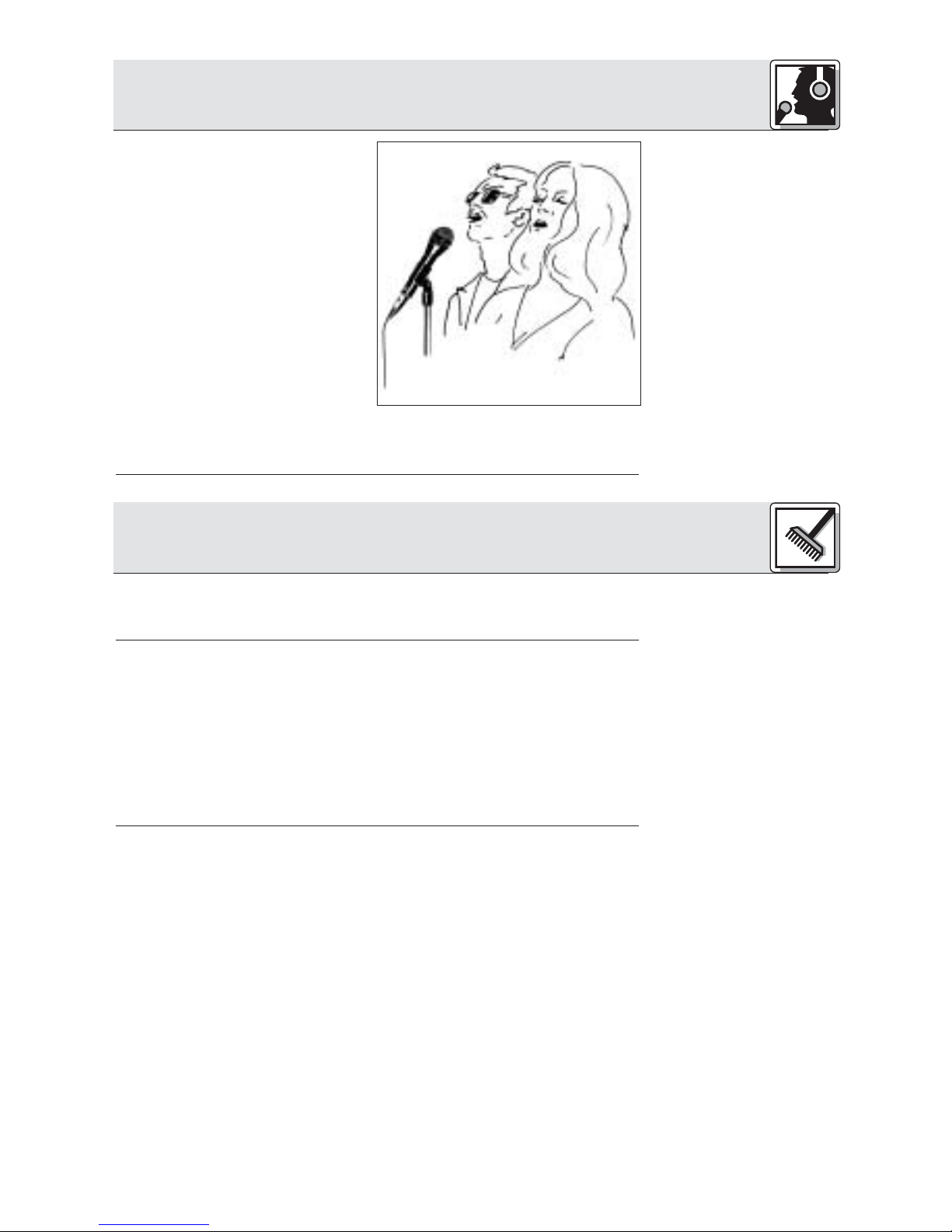
AKG D 3700 User manual

Bedienungsanleitung. . . . . . . . . . . . S. 2
Bitte vor Inbetriebnahme des Gerätes lesen!
User Instructions. . . . . . . . . . . . . . p. 12
Please read the manual before using the equipment!
Mode d’emploi. . . . . . . . . . . . . . . . p. 22
Veuillez lire cette notice avant d’utiliser le système!
Istruzioni per l’uso. . . . . . . . . . . . . p. 32
Prima di utilizzare l’apparecchio, leggere il manuale
Modo de empleo . . . . . . . . . . . . . . p. 42
¡Sirvase leer el manual antes de utilizar el equipo!
Instruções de uso . . . . . . . . . . . . . p. 52
Por favor leia este manual antes de usar o equipamento!
D 3700M
D 3700MS
D 3700M/TM 40

Überprüfen Sie bitte, ob das Gerät, an das Sie das Mikrofon
anschließen möchten, den gültigen Sicherheitsbestimmungen
entspricht und mit einer Sicherheitserdung versehen ist.
Kontrollieren Sie bitte, ob die Verpackung alle oben angeführ-
ten Teile enthält. Falls etwas fehlt, wenden Sie sich bitte an
Ihren AKG-Händler.
•Frequenzgang speziell für Gesangsübertragung ausgelegt.
•Integriertes Wind- und Popfilter unterdrückt wirkungsvoll
Pop- und Atemgeräusche.
•Gute Rückkopplungsunterdrückung durch frequenzunab-
hängige nierenförmige Richtwirkung.
•Brillante Übertragungsqualität durch neue Varimotion-
Membrantechnologie.
•Elastische Doubleflex-Lagerung des Wandlersystems redu-
ziert Griff- und Kabelgeräusche.
•Sicherer Schutz des Mikrofonwandlers durch nahezu unde-
formierbare Gitterkappe aus Federstahl
•Einbauschacht für optionales Sendermodul TM 40
1.1 Sicherheits-
hinweis
1.2 Lieferumfang
1.3 Empfohlenes
Zubehör
1.4 Besondere
Merkmale
2
1 Sicherheitshinweis/Beschreibung
• Mikrofonkabel MK 9/10: 10 m 2-polig geschirmtes
Kabel mit XLR-Stecker und XLR-Kupplung
• Sendermodul TM 40
• Windschutz W 23, W 3001
• Elastische Universal-Aufhängung H 30,
Stativanschluss SA 26
• Bodenstative ST 102A, ST 200,
ST 305
1 D 3700
M
oder D 3700
M
S
oder D 3700
M
/TM 40
1 SA 61 1 Mikrofonkoffer

1.5 D 3700M,
D 3700M/TM 40
Abb. 1:
Ergonomisch
optimierte
Gehäuseform
Abb. 2: Optionales
Sendermodul TM 40
Das D 3700
M
von AKG ist ein dynamisches Mikrofon mit nieren-
förmiger Richtcharakteristik, konzipiert für den Vokaleinsatz auf
der Bühne. Eine leichte Anhebung der Empfindlichkeit zwi-
schen 3 und 15 kHz verschafft der Stimme die nötige Durch-
setzungskraft auch bei sehr hoher Lautstärke auf der Bühne
und sorgt für gute Textverständlichkeit.
Der Hochleistungs-Neodym-Wandler mit Varimotion-Membran
liefert einen hohen Ausgangspegel und garantiert einen verzer-
rungsfreien, kräftigen Sound. Hand- und Kabelgeräusche wer-
den durch die elastische Doubleflex-Lagerung des Wandlers
weitgehend unterdrückt. Der Innenwindschutz reduziert Popp-,
Wind- und Atemgeräusche auf ein Minimum.
Eine robuste, nahezu unverformbare Gitterkappe aus Feder-
stahl und das stabile Zink-Alu-Druckgussgehäuse schützen
das Mikrofon und die Kapsel wirksam vor Beschädigungen im
harten Alltag "on the road".
Das D 3700
M
ist mit einem abnehmbaren Anschlussmodul mit
3-poligem XLR-Stecker ausgestattet. Sie können das D 3700
M
sowohl an symmetrischen als auch asymmetrischen Mischpult-
und Verstärkereingängen betreiben.
Die ergonomisch optimierte Form des
Gehäuses gewährleistet absolute
Funktionalität und exzellente Anwender-
freundlichkeit. Sie haben das Mikrofon
stets voll im Griff, egal, wie Sie es ein-
setzen.
Sie können das Mikrofon auf einfache
Weise in ein Drahtlos-Mikrofon umwan-
deln, indem Sie das XLR-Steckermodul
ausbauen und durch das optionale
Sendermodul TM 40 ersetzen.
1 Beschreibung
3

1.6 D 3700
M
S
Abb. 3:
Ein/Ausschalter des
D 3700
M
S
2.1 Schaltung
2.2 Anschluss an
symmetrischen
Eingang
Abb. 4: Anschluss
mittels symmetri-
schem XLR-Kabel
Siehe Abb. 4.
Das D 3700
M
Sist elektrisch, mechanisch
und akustisch identisch mit dem D 3700
M
,
besitzt jedoch ein XLR-Steckermodul mit
einem knackfreien Ein/Ausschalter. Der
Schalter ist versenkt angeordnet, um un-
beabsichtigtes Ausschalten zu verhindern.
Das Mikrofon besitzt einen symmetrischen Ausgang mit 3-poli-
gem XLR-Stecker:
Stift 1 = Masse
Stift 2 = Tonader (inphase)
Stift 3 = Tonader
Sie können das Mikrofon sowohl an symmetrische als auch
asymmetrische Mikrofoneingänge anschließen.
1. Verwenden Sie ein handelsübliches XLR-Kabel, z.B.
MK 9/10 von AKG (optionales Zubehör).
Die Länge dieses Kabels hat keinen Einfluss auf die
Signalqualität.
2. Stecken Sie die XLR-Kupplung des Mikrofonkabels an den
XLR-Stecker des Mikrofons an.
3. Stecken Sie den anderen Stecker des Mikrofonkabels an
den gewünschten Mikrofoneingang Ihres Mischpults oder
Verstärkers an.
1 Beschreibung
4
2 Anschluss

2.3 Anschluss an
asymmetrischen
Eingang
Abb. 5: Anschluss
mittels
asymmetrischem
Kabel
Siehe Abb. 5.
2.4 Optionales
Sendermodul
TM 40
Bauen Sie zuerst
das XLR-
Steckermodul aus:
Abb. 6: XLR-
Steckermodul
ausbauen
1. Wenn Sie das Mikrofon an einen asymmetrischen
Mikrofoneingang (6,3 mm-Klinkenbuchse) anschließen
wollen, verwenden Sie ein Kabel mit XLR-Kupplung und
6,3 mm-Mono-Klinkenstecker. Solche Kabel sind im
Musikfachhandel erhältlich.
Beachten Sie, dass asymmetrische Kabel Einstreuungen
aus Magnetfeldern (von Netz- und Lichtkabeln, Elektro-
motoren usw.) wie eine Antenne aufnehmen können. Bei
Kabeln, die länger als 5 m sind, kann dies zu Brumm- und
ähnlichen Störgeräuschen führen.
2. Stecken Sie die XLR-Kupplung des Mikrofonkabels an den
XLR-Stecker des Mikrofons an.
3. Stecken Sie den anderen Stecker des Mikrofonkabels an
den gewünschten Mikrofoneingang Ihres Mischpults oder
Verstärkers an.
Mit dem optionalen Sendermodul TM 40 von AKG können Sie
Ihr Mikrofon jederzeit in ein Funkmikrofon verwandeln, das Sie
mit jedem Empfänger der Serie WMS 40 von AKG betreiben
können.
2 Anschluss
5
1
2

Siehe Abb. 6.
Bauen Sie das
Sendermodul ein:
Abb. 7:
Sendermodul
einbauen
Siehe Abb. 7.
Hinweis:
Wenn Sie das
Sendermodul
wieder gegen das
XLR-Steckermodul
austauschen
wollen:
Siehe Abb. 8.
1. Öffnen Sie die Fixierungsschraube (1).
2. Ziehen Sie das XLR-Steckermodul (2) aus dem Mikrofon-
schaft heraus.
3. Damit Sie die Fixierungsschraube (1) nicht verlieren, drehen
Sie sie wieder in das Gewinde am XLR-Steckermodul hin-
ein.
1. Vergessen Sie nicht, den Zustand der Batterie im Sender-
modul zu kontrollieren. Legen Sie eine neue Batterie ein,
falls die derzeitige verbraucht ist oder sich gar keine
Batterie im Sendermodul befindet.
2. Halten Sie das Sendermodul (1) so, dass die Kontakte (2)
zum Mikrofon zeigen.
3. Schieben Sie das Sendermodul (1) so weit in den Mikrofon-
schaft hinein, bis das Sendermodul (1) hörbar einrastet.
Das Sendermodul verriegelt sich automatisch, die elektri-
schen Kontakte zum Mikrofon werden automatisch herge-
stellt.
Näheres zum Einlegen, Tauschen und Testen der Batterie
sowie zum Einstellen und Betrieb des Sendermoduls finden
Sie in der Bedienungsanleitung des Sendermoduls TM 40.
1. Führen Sie einen Kugelschreiber, kleinen Schraubenzieher
oder ähnlichen spitzen Gegenstand in die Öffnung (1) im
Mikrofonschaft ein und drücken Sie nach innen.
Das Sendermodul (2) wird entriegelt und gleitet ca. 2 mm
aus dem Mikrofonschaft heraus.
2. Ziehen Sie das Sendermodul (2) vom Mikrofon ab.
3. Drehen Sie die Fixierungsschraube (4) aus dem XLR-
Steckermodul (3) heraus.
4. Schieben Sie das XLR-Steckermodul (3) bis zum Anschlag
in den Mikrofonschacht hinein.
5. Fixieren Sie das XLR-Steckermodul (3), indem Sie die
Fixierungsschraube (4) fest anziehen.
2 Anschluss
6
1
2

Abb. 8:
Sendermodul
ausbauen
Hinweis:
3.1 Einleitung
3.2
Besprechungs-
abstand und
Naheffekt
3.3 Schall-
einfallswinkel
Siehe Abb. 9.
Sie können das Sendermodul auch ausbauen, indem Sie das
Sendermodul einfach nur kräftig aus dem Mikrofon heraus-
ziehen. Achten Sie darauf, das Sendermodul dabei nicht am
Batteriefachdeckel anzufassen. (Sie würden sonst lediglich das
Batteriefach öffnen.)
Ein Gesangsmikrofon bietet Ihnen viele Möglichkeiten, den
Klang Ihrer Stimme, wie er durch die Beschallungsanlage wie-
dergegeben wird, zu gestalten.
Beachten Sie bitte die folgenden Hinweise, um Ihr Mikrofon
optimal einsetzen zu können.
Die folgenden Kapitel gelten sowohl für die kabelgebundene
Ausführung des D 3700M/D 3700MS als auch für beide Mikro-
fone mit eingebautem optionalem Sendermodul TM 40.
Grundsätzlich wird Ihre Stimme umso voller und weicher wie-
dergegeben, je kürzer der Abstand zwischen den Lippen und
dem Mikrofon ist, während bei größerer Mikrofondistanz ein
halligeres, entfernteres Klangbild zustande kommt, da die
Akustik des Raumes mehr zur Geltung kommt.
Sie können daher Ihre Stimme aggressiv, neutral oder einschmei-
chelnd klingen lassen, indem Sie den Mikrofonabstand verändern.
Der Neheffekt tritt im unmittelbaren Nahbereich der
Schallquelle (weniger als 5 cm) auf und bewirkt eine starke
Betonung der Tiefen. Er verleiht Ihrer Stimme einen voluminö-
seren, intimen, bassbetonten Klang.
Singen Sie seitlich auf das Mikrofon oder über den Mikrofon-
kopf hinweg. So erhalten Sie einen ausgewogenen, naturge-
treuen Klang.
2 Anschluss
7
3 Anwendung
4
12
3

Abb. 9: Typische
Mikrofonposition
3.4 Rückkopplung
Abb. 10:
Mikrofonaufstellung
für minimale
Rückkopplung
Siehe Abb. 10.
Wenn Sie direkt von vorne auf
das Mikrofon singen, werden
nicht nur Atemgeräusche mit-
übertragen, sondern auch
Verschlusslaute (p, t) und
Zischlaute (s, sch, tsch) un-
natürlich hervorgehoben.
Die Rückkopplung kommt
dadurch zustande, dass ein
Teil des von den Laut-
sprechern abgegebenen
Schalls vom Mikrofon aufge-
nommen und verstärkt wieder
den Lautsprechern zugeleitet
wird. Ab einer bestimmten
Lautstärke (der Rückkopp-
lungsgrenze) läuft dieses
Signal gewissermaßen im
Kreis, die Anlage heult und
pfeift und kann nur durch
Zurückdrehen des Lautstärkereglers wieder unter Kontrolle
gebracht werden.
Um dieser Gefahr zu begegnen, hat das Mikrofon eine nieren-
förmige Richtcharakteristik. Das bedeutet, dass es für Schall,
der von vorne einfällt (die Stimme) am empfindlichsten ist,
während es auf seitlich einfallenden Schall oder Schall, der von
hinten auftrifft (z.B. von Monitorlautsprechern), kaum anspricht.
Minimale Rückkopplungsneigung erreichen Sie, indem Sie die
PA-Lautsprecher vor den Mikrofonen (am vorderen Bühnen-
rand) aufstellen.
Wenn Sie Monitorlautsprecher verwenden, lassen Sie Ihr
Mikrofon nie direkt auf die Monitore oder die PA-Lautsprecher
zeigen.
Rückkopplung kann auch durch Resonanzerscheinungen (als
Folge der Raumakustik), besonders im unteren
Frequenzbereich, ausgelöst werden, also indirekt durch den
Naheffekt. In diesem Fall brauchen Sie oft nur den
Mikrofonabstand zu vergrößern, um die Rückkopplung zum
Abreißen zu bringen.
3 Anwendung
8

3.5 Begleitchor
Abb. 11:
Mikrofonaufstellung
für Begleitduo
4.1 Gehäuse-
oberfläche
4.2 Innen-
windschutz
1. Lassen Sie nie mehr als
zwei Personen in ein
gemeinsames Mikrofon
singen.
2. Achten Sie darauf, dass
der Schalleinfallswinkel nie
größer als 35° ist.
Das Mikrofon ist für seit-
lich einfallenden Schall
sehr unempfindlich. Wenn
die beiden VokalistInnen
aus einem größeren Win-
kel als 35° auf das Mikro-
fon singen, müssten Sie den Pegelregler des Mikrofon-
kanals so weit aufziehen, dass die Rückkopplungsgefahr zu
groß würde.
Reinigen Sie die Gehäuseoberfläche des Mikrofons mit einem
mit Wasser befeuchteten Tuch.
1. Schrauben Sie die Gitterkappe des Mikrofons gegen den
Uhrzeigersinn ab.
2. Nehmen Sie den Windschutz aus der Gitterkappe heraus
und reinigen Sie den Windschutz mit Seifenwasser.
3. Lassen Sie den Windschutz über Nacht trocknen.
4. Legen Sie den Windschutz in die Gitterkappe ein und
schrauben Sie die Gitterkappe im Uhrzeigersinn auf das
Mikrofon auf.
3 Anwendung
9
4 Reinigung

5 Fehlerbehebung
10
Kein Ton.
Verzerrungen.
Mikrofon klingt mit der
Zeit immer dumpfer.
1. Mischpult und/oder
Verstärker ausgeschaltet.
2. Kanal- oder Summen-
Fader am Mischpult
oder Lautstärkeregler
des Verstärkers steht
auf Null.
3. Mikrofon nicht an
Mischpult oder Verstärker
angeschlossen.
4. Kabelstecker nicht
richtig angesteckt.
5. Kabel defekt.
6. Sendermodul aus- oder
stummgeschaltet.
7. Keine/leere Batterie im
Sendermodul.
8. Empfänger ausgeschal-
tet/nicht ans Mischpult
angeschlossen.
1. Gain-Regler am
Mischpult oder
Sendermodul nicht rich-
tig eingestellt.
2. Mischpulteingang zu
empfindlich.
•Verschmutzter
Innenwindschutz oder
Außenwindschutz
dämpft hohe
Frequenzen.
1. Mischpult und/oder
Verstärker einschalten.
2. Kanal- oder Summen-
Fader am Mischpult
oder Lautstärkeregler
des Verstärkers auf
gewünschten Pegel
einstellen.
3. Mikrofon an Mischpult
oder Verstärker ansch-
ließen.
4. Kabelstecker nochmals
anstecken.
5. Kabel überprüfen und
falls nötig ersetzen.
6. Sendermodul einschal-
ten.
7. Volle Batterie in
Sendermodul einlegen.
8. Empfänger
einschalten/an das
Mischpult anschließen.
1. Gain-Regler so einstel-
len, dass Verzerrungen
verschwinden.
2. 10-dB-Vorabschwächung
zwischen Mikrofonkabel
und Eingang stecken.
•Innenwindschutz bzw.
Außenwindschutz
reinigen.
Fehler Mögliche Ursache Abhilfe

6 Technische Daten
11
Richtcharakteristik: Niere
Übertragungsbereich: 70 - 20.000 Hz
Empfindlichkeit: 2,2 mV/Pa (-53 dBV)
Grenzschalldruckpegel (k=1%/3%): 147/156 dB SPL
Äquivalentschalldruckpegel: 19 dB-A (nach DIN 45412)
Elektrische Impedanz: 600 Ohm
Empfohlene Lastimpedanz: ≥2.000 Ohm
Anschlussstecker: 3-poliger XLR-Stecker
Oberfläche: matt-schwarz
Abmessungen: 50 Ø x 186 mm
Netto/Bruttogewicht: 290 /970 g
Dieses Produkt entspricht der Norm EN 50 082-1, vorausgesetzt, dass nachgeschaltete
Geräte CE-konform sind.
Frequenzgang Polardiagramm

1.1 Precaution
1.2 Unpacking
1.3 Optional
Accessories
1.4 Features
Please make sure that the piece of equipment your microphone
will be connected to fulfills the safety regulations in force in your
country and is fitted with a ground lead.
Check that the packaging contains all of the components listed
above. Should anything be missing, please contact your AKG
dealer.
•Frequency response optimized for vocal use.
•Integrated wind and pop screen for effective suppression of
pop and breath noise.
•Frequency independent cardioid polar pattern for high gain
before feedback.
•New Varimotion diaphragm for brilliant sound.
•Doubleflex shock mount on transducer element reduces
handling and cable noise.
•Extremely resilient, spring-steel wire-mesh cap for extra
impact resistance.
•Installation slot for optional TM 40 transmitter module.
1 Precaution/Description
12
1 D 3700Mor D 3700MS
or 3700M/TM 40
1 SA 61 1 Carrying case
• MK 9/10 microphone cable: 10 m (30 ft.)
2-conductor shielded cable with 3-pin male and
3-contact female XLR connectors
• TM 40 transmitter module
• W 23, W 3001 windscreens
• H 30 universal elastic suspension,
SA 26 stand adapter
• ST 102A, ST 200, ST 305
floor stands

1.5 D 3700M,
D 3700M/TM 40
Fig. 1:
Ergonomically opti-
mized shape.
Fig. 2: Optional
TM 40 transmitter
module.
The AKG D 3700Mis a dynamic cardioid microphone designed
for vocal use on stage. A slight sensitivity peak between 3 kHz
and 15 kHz provides good intelligibility and will make your voice
cut through the loudest mix on stage.
A high-flux neodymium transducer with a Varimotion dia-
phragm delivers a high output level and powerful, distortion free
sound. The Doubleflex shock mount on the transducer mini-
mizes handling and cable noise. An integrated windscreen
reduces pop, wind, and breath noise to a minimum.
A rugged front grill made of spring-steel wire mesh that is
extremely resistant to deformation and a sturdy zinc alloy die-
cast body effectively protect the microphone and transducer
element from damage on stage and on the road.
The D 3700Mfeatures a removable connection module with a
3-pin XLR connector. You can connect the microphone to both
balanced and unbalanced mixer or amplifier inputs.
The microphone body has been specifical-
ly designed for fatigue-free handling and
ease of use. No matter what microphone
technique you use, the microphone will
always settle comfortably into your hand.
You can easily convert the microphone
into a wireless microphone. All you need
to do is remove the XLR connector mod-
ule and replace it with an optional TM 40
transmitter module.
1 Description
13

Fig. 3: On/off switch
on D 3700MS.
2.1 Output Circuit
2.2 Connecting
the Microphone
to a Balanced
Input
Fig. 4: Using a bal-
anced connecting
cable.
Refer to fig. 4.
The D 3700MShas the same mechanical,
electrical, and acoustic characteristics as
the D 3700Mand features an XLR connec-
tor module with a noiseless on/off switch.
The switch is recessed to prevent the
microphone being switched off uninten-
tionally.
The microphone provides a balanced output on a 3-pin male
XLR connector:
Pin 1: ground
Pin 2: hot
Pin 3: return
You can connect the microphone either to a balanced or an
unbalanced microphone input.
1. Use a commercial XLR cable such as the optional MK 9/10
from AKG.
The length of these cables does not affect audio quality.
2. Plug the female XLR connector on the microphone cable
into the male XLR connector on the microphone.
3. Plug the other connector on the microphone cable into the
desired microphone input socket on your mixer or amplifier.
1 Description
14
2 Interfacing

2.3 Connecting
the Microphone
to an Unbalanced
Input
Fig. 5: Using an
unbalanced cable.
Refer to fig. 5.
2.4 Optional TM 40
Transmitter
Module
Start by removing
the XLR connec-
tor module:
Fig. 6: Removing
the XLR connector
module.
Refer to fig. 6.
1. To connect the microphone to an unbalanced microphone
input (1/4" jack), use a cable with a female XLR connector
and a 1/4" TS jack plug. These cables are available at music
stores.
Please note that unbalanced cables may pick up interfer-
ence from stray magnetic fields near power or lighting
cables, electric motors, etc. like an antenna. This may cause
hum or similar noise when you use a cable that is longer
than 16 feet (5 m).
2. Plug the female XLR connector on the microphone cable
into the male XLR connector on the microphone.
3. Plug the other connector on the microphone cable into the
desired microphone input jack on your mixer or amplifier.
The optional TM 40 transmitter module allows you to convert
your microphone into a wireless microphone that you can use
with any WMS 40 Series receiver from AKG.
1. Open the fixing screw (1).
2. Pull the XLR connector module (2) out of the microphone
body.
2 Interfacing
15
1
2

Install the trans-
mitter module:
Fig. 7: Installing the
transmitter module.
Refer to fig. 7.
Note:
Replacing the
transmitter
module with the
XLR connector
module:
Fig. 8: Removing
the transmitter
module.
Refer to fig. 8.
3. To avoid losing the fixing screw (1), screw it into the thread-
ed hole (3) in the XLR connector module.
1. Do not forget to check the condition of the battery inside the
transmitter module. If the battery is dead or there is no bat-
tery inside the transmitter module, insert a new battery.
2. Hold the transmitter module (1) to align the contacts (2) with
the microphone.
3. Slide the transmitter module (1) into the microphone body to
the point that the transmitter module (1) will lock with an
audible click.
As the transmitter module locks in place, the electrical con-
nections to the microphone are made automatically.
For details on inserting, replacing, and testing the battery as
well as setting up and operating the transmitter module
refer to the TM 40 transmitter module manual.
1. Insert a ball point pen, small screwdriver, or similar pointed
object into the opening (1) in the microphone body and
press inward.
2 Interfacing
16
1
2
4
12
3

Refer to fig. 8.
Note:
3.1 Introduction
3.2 Working
Distance and
Proximity Effect
The transmitter module (2) will unlock and slide out of the
microphone body for about 0.1 inch.
2. Pull the transmitter module (2) out of the microphone.
3. Unscrew the fixing screw (4) from the XLR connector mod-
ule (3).
4. Slide the XLR connector module (3) into the microphone
body to the stop.
5. To fix the XLR connector module (3), screw the fixing screw
(4) down firmly.
Alternatively, you can remove the transmitter module simply by
pulling it out of the microphone body with just enough force to
unlock it. Make sure not to grasp the transmitter module by the
battery compartment. (If you did, you would only open the bat-
tery compartment.)
A handheld vocal microphone provides many ways of shaping
the sound of your voice as it is heard over the sound system.
The following sections contain useful hints on how to use your
microphone for best results.
The following sections apply to both the hardwire D 3700M/
D 3700MS and either version with an optional TM 40 transmit-
ter module installed.
Basically, your voice will sound the bigger and mellower, the
closer you hold the microphone to your lips. Moving away from
the microphone will produce a more reverberant, more distant
sound as the microphone will pick more of the room’s rever-
beration.
You can use this effect to make your voice sound aggressive,
neutral, insinuating, etc. simply by changing your working dis-
tance.
Proximity effect is a more or less dramatic boost of low fre-
quencies that occurs when you sing into the microphone from
less than 2 inches. It gives more "body" to your voice and an
intimate, bass-heavy sound.
2 Interfacing
17
3 Using Your Microphone

3.3 Angle of
Incidence
Fig. 9: Typical
microphone
position.
3.4 Feedback
Fig. 10: Microphone
placement for maxi-
mum gain before
feedback.
Refer to fig. 10.
Sing to one side of the micro-
phone or above and across
the microphone’s top. This
provides a well-balanced, nat-
ural sound.
If you sing directly into the
microphone, it will not only
pick up excessive breath
noise but also overemphasize
"sss", "sh", "tch", "p", and "t"
sounds.
Feedback is the result of part
of the sound projected by a
speaker being picked up by a
microphone, fed to the ampli-
fier, and projected again by
the speaker. Above a specific
volume or "system gain" set-
ting called the feedback
threshold, the signal starts
being regenerated indefinitely,
making the sound system
howl and the sound engineer
desperately dive for the mas-
ter fader to reduce the volume and stop the howling.
To increase usable gain before feedback, the microphone has a
cardioid polar pattern. This means that the microphone is most
sensitive to sounds arriving from in front of it (your voice) while
picking up much less of sounds arriving from the sides or rear
(from monitor speakers for instance).main ("FOH") speakers in
front of the microphones (along the front edge of the stage).
If you use monitor speakers, be sure never to point any micro-
phone directly at the monitors, or at the FOH speakers.
Feedback may also be triggered by resonances depending on
the acoustics of the room or hall. With resonances at low fre-
quencies, proximity effect may cause feedback. In this case, it
is often enough to move away from the microphone a little to
stop the feedback.
3 Using Your Microphone
18

3.5 Backing
Vocals
Fig. 11: Two vocal-
ists sharing a micro-
phone.
4.1 Microphone
Body
4.2 Internal
Windscreen
1. Never let more than two
persons share a micro-
phone.
2. Ask your backing vocalists
never to sing more than 35
degrees off the micro-
phone axis.
The microphone is very
insensitive to off-axis
sounds. If the two vocal-
ists were to sing into the
microphone from a wider
angle than 35 degrees,
you may end up bringing up the fader of the microphone
channel far enough to create a feedback problem.
To clean the surface of the microphone body, use a soft cloth
moistened with water.
1. Unscrew the front grill from the microphone CCW.
2. Remove the windscreen from the from grill and wash the
windscreen in soap suds.
3. Allow the windscreen to dry overnight.
4. Replace the windscreen in the front grill and screw the front
grill on the microphone CW.
3 Using Your Microphone
19
4 Cleaning

5 Troubleshooting
20
No sound.
Distortion.
Microphone sound
becomes duller by and
by.
1. Power to mixer and/or
amplifier is off.
2. Channel or master fader
on mixer, or volume
control on amplifier is at
zero.
3. Microphone is not con-
nected to mixer or
amplifier.
4. Cable connectors are
seated loosely.
5. Cable is defective.
6. Transmitter module is off
or muted.
7. No/dead battery in
transmitter module.
8. Receiver is off or not
connected to mixer.
1. Gain control on mixer or
transmitter module not
set correctly.
2. Mixer input sensitivity
too high.
•Internal or external
windscreen attenuates
high frequencies when
soiled.
1. Switch power to mixer
or amplifier on.
2. Set channel or master
fader on mixer or vol-
ume control on amplifier
to desired level.
3. Connect microphone to
mixer or amplifier.
4. Check cable connectors
for secure seat.
5. Check cable and
replace if damaged.
6. Switch transmitter mod-
ule on.
7. Insert new/fully charged
battery.
8. Switch receiver on or
connect to mixer.
1. Set gain control to stop
distortion.
2. Insert 10 dB preattenua-
tion pad between micro-
phone cable and input.
•Clean internal or exter-
nal windscreen.
Problem Possible Cause Remedy
Other manuals for D 3700
2
This manual suits for next models
2
Table of contents
Languages:
Other AKG Microphone manuals