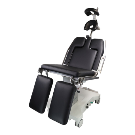
AKRUS ak 5010 MBS User manual

ak 5010 MBS
Mobile Mammography Chair
User Manual

277g001e_ak5010_3rd ed_MDR_REV 7.0.docx26.05.2021Page 2 of 23
Index
1GENERAL ................................................................................................................................................. 3
1.1 COPYRIGHT................................................................................................................................................ 3
1.2 DISCLAIMER ............................................................................................................................................... 3
1.3 APPLICABLE RULES AND REGULATIONS............................................................................................................. 3
1.4 WARNING AND CAUTIONING SIGNS................................................................................................................. 3
1.5 USER INSTRUCTIONS FOR SAFE OPERATION....................................................................................................... 4
1.6 PRODUCT DENOMINATION ............................................................................................................................ 4
2USEFUL LIFE AND WARRANTY CONDITIONS ............................................................................................ 5
3SCOPE OF DELIVERY................................................................................................................................. 5
4INTENDED USE......................................................................................................................................... 5
4.1 INTENDED USE ............................................................................................................................................ 6
5MOUNTING AND COMMISSIONING......................................................................................................... 6
6ELECTRICAL CONNECTIONS...................................................................................................................... 6
7PRODUCT DESCRIPTION AND CONTROLS................................................................................................. 6
7.1 BATTERY (100-925) ................................................................................................................................... 6
7.2 BATTERY RE CHARGING INTERVALS.................................................................................................................. 7
7.3 BATTERY RE CHARGER UNIT (100-924)........................................................................................................... 7
7.4 BATTERY HOLDER AT THE AK 5010 MBS CHAIR ................................................................................................ 8
7.5 ELECTRIC LIFT (101-016 /101-017) AND FOOT SWITCH (277.012003)............................................................. 8
7.6 SAFETY SWITCH........................................................................................................................................... 8
7.7 CONTROL LEVER FOR HEAVY DUTY CASTORS...................................................................................................... 9
7.8 WARNING AND CAUTIONING SIGNS ON THE CHAIR ........................................................................................... 10
8OPERATION OF CHAIR ............................................................................................................................13
8.1 DUTY CYCLE (CONTINUOUS OPERATION)OF ELECTRICAL MOTORS........................................................................ 13
8.1.1 Battery charge status (see also 7.2) ................................................................................................ 13
8.2 ENTRY AND EXIT POSITION .......................................................................................................................... 13
8.2.1 Foot rest adapter (277.950300)....................................................................................................... 13
8.2.2 Adjustment of armrests ................................................................................................................... 14
8.2.3 Adjustment of back rest................................................................................................................... 14
8.2.4 Adjustment of head rest (277.030600 / 277.030700) ..................................................................... 14
8.2.5 Adjustment of back rest segments .................................................................................................. 15
8.2.6 Lateral back support (277.032010).................................................................................................. 15
8.2.7 Lateral orientation (park bench)...................................................................................................... 15
8.2.8 Trendelenburg (277.025010) ........................................................................................................... 16
9CLEANING AND CONTAMINATION PROTECTION ....................................................................................16
10 MAINTENANCE .......................................................................................................................................16
11 PRODUCT SAFETY INSPECTION ...............................................................................................................16
12 DISPOSAL OF DEVICE ..............................................................................................................................17
13 TECHNICAL DATA....................................................................................................................................17
14 ENVIRONMENTAL CONDITIONS..............................................................................................................18
15 TROUBLE SHOOTING ..............................................................................................................................18
16 CE CONFORMITY.....................................................................................................................................18
17 MANUFACTURER ....................................................................................................................................18
18 ELECTROMAGNETIC COMPATIBILITY EMC ..............................................................................................19

277g001e_ak5010_3rd ed_MDR_REV 7.0.docx26.05.2021Page 3 of 23
1General
To safely operate and control the ak 5010 MBS please carefully read this user manual before operating.
Please pay attention to all cautionary statements pertaining to the safe operation of the ak 5010 MBS.
Please keep the manual on file at all times while the product is in service.
The manufacturer reserves the right to make technical changes or modifications in accordance with
advanced technical developments. This manual is not subject to an updating service.
1.1 Copyright
© Distributing, copying or any commercial use of this manual is strictly prohibited unless expressly
permitted in writing by the manufacturer. The manufacturer is entitled to compensation for any viola-
tion of this right.
The manufacturer claims any and all rights in case a patent is granted or the design is registered.
1.2 Disclaimer
Manufacturer excludes any and all liabilities in case of improper or not authorized operation or mainte-
nance or servicing of the product.
1.3 Applicable rules and regulations
The device complies with the following Regulations for medical devices.
o2017/745
oDIN / ISO 60601-1
oDIN / ISO 60601-1-2 EMC
oUMDNS No 16-437
oDevice classification according to MDR Medical Device Class I
The device meets the requirements MDR 2017/745
User must observe the national legal requirements governing the prevention of accidents.
1.4 Warning and cautioning signs
Warning
Indicates a hazardous situation which may result in fatal or serious bod-
ily injury if the appropriate safety precautions are not heeded.
Caution
Indicates a hazardous situation which may result in minor injury if the
appropriate safety precautions are not heeded.
This pictograph on the label indicates:
Equipment Category B according to EN 60601-1

277g001e_ak5010_3rd ed_MDR_REV 7.0.docx26.05.2021Page 4 of 23
1.5 User instructions for safe operation
Before using this medical device, please carefully read and observe the safety instructions and
recommendations listed in this manual
oTo safely use and operate the medical device, use only as directed.
oOperation of the medical device only in accordance with the intended use.
oDo not operate the medical device in explosive or hazardous environments. The device is not
suitable for operation in explosion risk areas (e.g. combustible mixture of anesthetic, cleaning
or disinfecting agents with air, oxygen or nitrous oxide).
oDo not set up the medical device in humid or damp rooms. Never expose the product to sprin-
kling, dripping or splashing water.
oPay special attention to any emphasized safety instructions or information in this user manual.
1.6 Product denomination
Product de-
nomination
Order no UDI
ak 5010 MBS
277.000000
04260647941517
277.000004
04260647941524
277.000005
04260647941531
277.000007
04260647941555
Accessories: see current price list and section 8,2
Caution
Risk of operat-
ing errors
The device may only be installed, operated, used and maintained
by persons who have been properly trained or who have the re-
quired knowledge and experience to do so. Please also adhere to
the national qualification guidelines applicable in your country.

277g001e_ak5010_3rd ed_MDR_REV 7.0.docx26.05.2021Page 5 of 23
2Useful life and warranty conditions
The useful product life is expected to be 8 years. Both, the useful life time and the warranty offered by
manufacturer are conditional upon the adherence to the conditions outlined below.
3Scope of delivery
The ak 5010 MBS scope of delivery comprises
Position
Qty
ak 5010 MBS examination chair
1
Re charger unit incl. power cord
1
Battery
1
Quality- test report
1
User Manual
1
Options according to order
4Intended use
oThe ak 5010 MBS is intended for use as an examination chair. Any other use of the product is not
permitted
oThe ak 5010 MBS is designed for a maximum patient weight of 135 kg (330 lbs) A 250 kg (550 lbs)
version is available upon request.
oThe headrest is designed for a maximum load of 20 kg (44 lbs).
oThe chair is suitable to be used in the immediate proximity of patients.
oThe device may only be operated with the battery supplied with the device. To re charge the
battery, remove battery from the device and use the recharger unit supplied with the device.
Caution
Risk of operat-
ing errors
The device may only be installed, operated, used and maintained
by persons who have been properly trained or who have the re-
quired knowledge and experience to do so. Please also adhere to
the national qualification guidelines applicable in your country.
Caution
General Haz-
ards
The development, production and maintenance of these medical
devices, together with associated risks, are based on an expected
service life of eight years, provided the device is serviced at the
specified intervals.
Modifications to the product or failure to follow the manufac-
turer’s instructions may substantially reduce the expected service
life and significantly increase the risks associated with the use of
this device.
It is the responsibility of the institution operating this product to
follow the man
ufacturer’s instructions and to decide on the
risk/benefit ratio upon expiration of the expected service life or
maintenance and inspection intervals specified by the manufac-
turer.
Caution
General Haz-
ards
The product is only operated in compliance with the provisions of
the intended use and the environmental conditions set forth in the
chapter “Ambient conditions”

277g001e_ak5010_3rd ed_MDR_REV 7.0.docx26.05.2021Page 6 of 23
4.1 Intended use
The medical has been designed to support / position patients for diagnostic or therapeutic pro-
cedures. The standards covering operating tables (EN 60601-2-46) are not applicable for this
product.
The essential performance is the ability to position a patient in a controlled manner by
means of control elements, within the scope of movement possibilities. The movements
must neither be continued with the omission of the operating command nor initiated by
external influences such as electromagnetic interference
(Proof, resistance to EM radiation in accordance with DIN/ISO 60601-1-2 EMV).
5Mounting and commissioning
The medical device is delivered fully assembled. If optional parts or accessories are part of the delivery,
please refer to the respective section in this user manual for mounting or connecting instructions.
No additional assembly or calibration work is required to operate the medical device.
6Electrical connections
Find the location of the power input on the device or the battery charger unit in the respective sec-
tion of this user manual. To connect the device to the power supply use only the power cable deliv-
ered with the devices or as specified by the manufacturer.
7Product description and controls
7.1 Battery (100-925)
The electric actuator is powered by a re chargeable battery.
Battery must be handled with care as the following miss handling may cause severe or fatal damage
to the battery:
- Total discharge
- Drop on hard surfaces (even from low heights)
- Short out of electrical connectors
Please also refer to chapter “Disposal of device”.
Warning
Electrical
shock
The medical device is only without electrical power after the battery has
been removed.

277g001e_ak5010_3rd ed_MDR_REV 7.0.docx26.05.2021Page 7 of 23
7.2 Battery re charging intervals
The battery should be re charged every 2-3 days, in case of heavy duty usage (> 30 full cycle move-
ments/day) re charge daily. The re charger protects the battery from damage by overloading, so the
battery may be re charged overnight or during the week end. It is not required to remove the battery
from the recharger after the recharging process is completed.
7.3 Battery re charger unit (100-924)
Attach the re charger unit permanently to the wall using two screws or set up at a suitable place. Make
sure the unit is oriented vertical to assure the gravity-assisted contact of the electrical metal contacts.
Make sure to place the recharger unit in a spot were the power cord is easily accessible in order to
disconnect the device from main power supply, if necessary.
The re charger unit is equipped with a voltage detecting power unit approved for 100V to 240V line
voltage. Battery Ready mode is indicated by a green LED.
The re charging process is indicated by a yellow LED and may take up to 4 hours. Upon completion the
yellow LED extinguishes. The electronic control of the re charger prevents an over charge, battery must
not be removed from charger after completion of charging process.
Control light
ON
Re charger unit with
power cord
Control light
CHARGE
Vertical orientation of re
charger unit
Warning
Electrical
shock
Remove battery from battery holder, if the device is not used for an
extended period of time.

277g001e_ak5010_3rd ed_MDR_REV 7.0.docx26.05.2021Page 8 of 23
7.4 Battery holder at the ak 5010 MBS chair
The battery holder is located under the lower frame and easily accessible. Pull at the spring loaded
handle at the head end of the battery to unlock and carefully remove battery from holder. To insert
battery in holder, slide battery in position applying a gentle push to battery and wait for the audible
click.
Position of battery holder
7.5 Electric lift (101-016 / 101-017) and foot switch (277.012003)
The ak 5010 MBS is powered by a low
voltage lift
The Up – Down movement are con-
trolled by two-foot operated
switches, one on either side of the
lower frame.
The arrows indicate the direction of
movement.
7.6 Safety switch
To avoid any unwanted Up – Down movement
during the procedure (biopsy needle inserted)
the ak 5010 features a safety switch located on
either side of the frame.
Push down the mushroom shaped head of the
switch to shut OFF the power. To switch ON
power, lift the lower head with the tip toes.
The functions of the safety switches are clearly
indicated by a red and a green mark.
Switch on green mark: power ON, chair
movements available
Switch on red mark: power OFF, chair
movements not available

277g001e_ak5010_3rd ed_MDR_REV 7.0.docx26.05.2021Page 9 of 23
7.7 Control lever for heavy duty castors
The chair features 4 heavy-duty cas-
tors and two foot levers on either side
of the lower frame.
The three settings below are available
-All wheels locked (kick on black arm)
-All wheels unlocked and swiveling (set arms horizontal)
-All wheel unlocked, one wheel set for steering (kick on green arm)
Foot operated control lever in different settings
all wheels locked
all wheels unlocked
one wheel locked for direc-
tional control
Proper operation of break
lever
To exert maximum push
force onto the brake lever,
place toes on break lever
using a sideways approach.
Improper operation of break lever
Do not place the foot onto the center of the axle or perpendicu-
lar to the frame. The might make it very hard to set the brake.

277g001e_ak5010_3rd ed_MDR_REV 7.0.docx26.05.2021Page 10 of 23
7.8 Warning and cautioning signs on the chair
1
2
3
3.1option

277g001e_ak5010_3rd ed_MDR_REV 7.0.docx26.05.2021Page 11 of 23
1
Manufacturer
Date of manufacturing
EU- symbol of confornity
Anwendungsteil vom Typ B
gemäß IEC 60601-1
Use only indoors.
do not dispose of through
general household waste
Order no/ part no
Serial no
Danger to patient, operator or
device
North America –
symbol of confornity
Identifier
Device is a medical
device
Unique device identification -
code (Data Matrix und
human readable text)
2
Safety switch, power ON
Safety switch, power OFF

277g001e_ak5010_3rd ed_MDR_REV 7.0.docx26.05.2021Page 12 of 23
3
Weight of chair
Max patient weight (135kg)
3.1
option
option
Weight of chair
Max patient weight (250kg)
4
Prohibition sign “DO NOT PLACE ANY
LOAD“
DIN 4844-2001
Any load > 200N is not permissible

277g001e_ak5010_3rd ed_MDR_REV 7.0.docx26.05.2021Page 13 of 23
8Operation of chair
8.1 Duty cycle (continuous operation) of electrical motors
The electrical motors are designed for a duty cycle of approximately 6 minutes at full load. Continuous
operations exceeding that time period may cause overheat conditions and permanent damage to the
transformer.
8.1.1 Battery charge status (see also 7.2)
After discharging the battery down to approximately 20% of total capacity, the chair will move signifi-
cantly slower, indicating that the battery is due for recharging. A total discharge may cause damage to
the battery.
8.2 Entry and exit position
The minimum seat cushion height
is at approximately 68 cm. A fold
away footrest may be used to as-
sist smaller or physically incapac-
itated patients to enter into or
get out of the chair.
Fold away footrest
8.2.1 Foot rest adapter (277.950300)
In order to assist smaller patients with shorter legs to comfortably sit in the chair, foot rest adapters
are available either as a single or a stackable dual block.
NOTE
These adapters are NOT designed as a STEP IN aid. If needed, attach the adapters after the patient has
been seated in the chair.
Attach single block:
Tilt and slide tongue into the
notch
Attach dual block:
First, slide the 2 blocks on
top of each other and then
proceed like above.

277g001e_ak5010_3rd ed_MDR_REV 7.0.docx26.05.2021Page 14 of 23
8.2.2 Adjustment of armrests
Both arm rests fold away upwards and can be
placed parallel to the back rest.
8.2.3 Adjustment of back rest
The back rest is infinitely ad-
justable from vertical to fully
horizontal. Pressing one of
the two spring loaded levers
behind the head rest (arrow)
unlocks the pneumatic gas
spring and the back rest will
gently move up or down.
8.2.4 Adjustment of head rest (277.030600 / 277.030700)
The ak 5010 features an infinitely height adjusta-
ble head rest, which is very comfortable for lat-
eral (park bench) patient positions. The knob eas-
ily moves the head rest up or down.
Caution
Over winding the full stop IN –OUT position by ap-
plying too much force on the knob may cause dam-
age to the adjustment mechanism.
The headrest max. 20 kg (44
lbs) can be moved left or
right.

277g001e_ak5010_3rd ed_MDR_REV 7.0.docx26.05.2021Page 15 of 23
8.2.5 Adjustment of back rest segments
The back rest offers two in-
dividually adjustable seg-
ments, allowing to position
patients laterally (park
bench). To make any adjust-
ment, secure segment with
one hand, then pull on the
peg (arrow). To lock seg-
ment in position, just let the
peg latch into the desired
lock hole.
8.2.6 Lateral back support (277.032010)
To attach the lateral back support, fold up the
arm rest in the back of patient to vertical and
slide the U shaped plastic arms of the support
pad over that arm rest. Position patient for-
ward to desired position relative to the exami-
nation equipment and latch the plastic peg into
the respective notch.
8.2.7 Lateral orientation (park bench)
The chair offers limitless positioning possibili-
ties thus allowing any examination or stereo-
tactic procedure to be performed on this chair.
The fold away back segment supports the
lower arm, while the head rest comfortably
supports patients head in a lateral (park bench)
position.
The back support helps to move the patient’s
chest wall to the very front end of the back rest
for easy access of the examination equipment.
At the same time it provides a relaxing support.

277g001e_ak5010_3rd ed_MDR_REV 7.0.docx26.05.2021Page 16 of 23
8.2.8 Trendelenburg (277.025010)
A manually operated Trendelenburg position is available.
Secure chair with one hand
at the foot rest.
Pull red handle foot ways to
unlock the Trendelenburg
mechanism. To lock the
Trendelenburg position, pull
back the handle to its origi-
nal position.
9Cleaning and contamination protection
oContamination protection
In order to protect the product against contamination by liquids, body liquids or other un-
wanted substances it is recommended to, while in use, cover the product with a non sterile
disposable impermeable cover sheet.
oSurfaces are resistant to all commonly used disinfectants as listed in the
D G H M (Deutsche Gesellschaft fuer Hygiene und Mikrobiologie) list.
http://www.gesundheitsamt.de/alle/technik/download/seuche/bakt/list/dghm.pdf. Any
apprpropriate desinfectant must not exceed the concentrations given for the following
ingredients. Propanol=35% // Ethanol=25% This would equal for example Terralin Liquid
offered by. Schülke&Mayr.
oDo not attempt to sterilize the ak 5010 MBS
oClean only the external surfaces of the equipment using a damp cloth. In case of heavy stains
do not use abrasive or aggressive materials other than common cleansers or detergents. Do
not use ether, acetone or concentrated acids.
oNo water or cleaning detergents may enter the inside of the equipment.
oTo clean soiled upholstery surfaces, use a damp cloth and/or commonly used upholstery spray.
oBefore resuming operation, allow sufficient time to dry.
10 Maintenance
The chair is maintenance free to users and operators.
Product is subject to the regular service intervals. Refer to the current issue of Manufacturers mainte-
nance record.
11 Product safety inspection
A product safety inspection is not required by manufacturer however, operator must adhere to any
current national regulations governing the requirements for medical products class I”.

277g001e_ak5010_3rd ed_MDR_REV 7.0.docx26.05.2021Page 17 of 23
12 Disposal of device
The battery and all electrical components must be disposed of in accordance with national applicable
laws and regulations.
All other components are household waste.
13 Technical Data
Technical Data
Value
Unit
Dimensions and weight
Length wheel base (backrest up)
760
mm
Width wheel base
580
mm
Width chair incl. attachment rails
760
mm
Width seat cushion
580
mm
Height chair back rest upright
1440
mm
Max. length chair, back rest horizontal
1730
mm
Max. patient weight
135/250
kg
Max. patient weight
300/550
lbs
Max chair load (static)
545
kg
Max chair load (static)
1200
lbs
Chair weight (depending on options)
95
kg
Vertical range chair (Z axis)
Lowest Entry height
680
mm
Lift
300
mm
Max height
980
mm
Range back rest
Vertical to horizontal
90
°
Shock position below horizontal
-15
°
Range head rest
Vertical, back rest horizontal
160
mm
Sideways
120
mm
Range shoulder segment
Fold down below horizontal
40
°
Wheel base
3 Pos. Brake system
all wheels pivoting
1 wheel locked for steering
all wheels locked
Wheel diameter
125
mm
Actuating force (brake) ± 10 %
250
N
Electrical data
Battery
24 (2,9)
Volt(Ah)
Period short time duty cycle Motors (ID 10)
ED 1,5/13,5
Min.
Upholstery electric conductible (optional)
Electrical data charger unit
Line power for re charger
100-240
Volt
Recharging time required
4
h
Nominal frequency
50 – 60
Hz
Nominal power
400
mA
Fuse
T 1,25 //250
A/H//V
Protection category
IP 65

277g001e_ak5010_3rd ed_MDR_REV 7.0.docx26.05.2021Page 18 of 23
14 Environmental Conditions
Ambient conditions for intended use
Ambient air temperature
+10° C - +40° C
Rel. Humidity max
50 % non-condensing
Ambient air pressure
700 – 1060 hPa
Ambient conditions for storage
Ambient air temperature
-10 °C to +55 °C
Rel. Humidity
10 % to 95 % non-condensing
Ambient conditions for storage and transport in original packaging
Ambient air temperature
-40 °C to +70 °C
Rel. Humidity
10 % to 95 % non-condensing
15 Trouble shooting
Fault/Malfunction
Possible cause
Corrective action
No function available
Battery discharged
Recharge battery
Safety switch in OFF position
Unlock safety switch (ref. to
sec.7.6)
Battery not properly snapped in
Check battery (ref. to sec.7.4)
No function available, bat-
tery charged
Battery defective
Call service
LED ON of re charger unit
not illuminated
Power cord not connected
Check power cord (ref. to
sec.7.2)
Re charger unit defective
Call service
LED CHARGE of re charger
unit not illuminated
Re charger unit or battery defective
Call service
Mechanical damages
External forces
Call service
16 CE Conformity
We declare the compliance of the device with the requirements of the Council Directive MDR 2017/745
about Medical Devices class I.
17 Manufacturer
AKRUS GmbH & Co KG
Otto-Hahn-Straße 3
D-25337 ELMSHORN
int. +49 (0) 4121 791930 Email: [email protected]
FAX int. +49 (0) 4121 791939 Website: www.akrus.de

277g001e_ak5010_3rd ed_MDR_REV 7.0.docx26.05.2021Page 19 of 23
18 Electromagnetic compatibility EMC
Electromagnetic compatibility
CAUTION - RISK OF ELECTROMAGNETIC INTERFERENCE
RADIATION
For the device, special precautions must be taken regarding EMC, and it must be
operated in accordance with the following requirements.
•The use of accessories, transducers of all kinds, and cables that are not
specified in these instructions or offered by Akrus as spare parts, may
cause an increased risk of emissions or reduced immunity of the unit.
•Portable and mobile HF communications equipment may cause an effect
to the ak 5010 MBS CHAIR. Use no cell phones and no other devices that
do not comply with the EMC class B CISPR 11 near the instrument.
•It cannot be excluded that an electromagnetic interference radiation may
lead to an unwanted interruption of the procedure.
•The ak 5010 MBS CHAIR is subject to particular precautions with regard to
electromagnetic compatibility (EMC). To avoid any unwanted EMC prob-
lems, do only use the ak 5010 MBS CHAIR as specified in this manual and
only such components supplied by Akrus may be installed, commissioned
and maintained.
•The ak 5010 MBS CHAIR has not been tested on electromagnetic compati-
bility with strong magnetic fields. The likely hood, that the presence of
strong magnetic fields on site may cause malfunctions of the product is very
minute. However, do not place the ak 5010 MBS CHAIR close to sources of
strong high-frequency magnetic fields.
•The ak 5010 MBS CHAIR may not be placed in the close proximity of, or
directly next to or stacked up with other devices. If it is necessary to
operate the ak 5010 MBS CHAIR close to or stacked up with other equip-
ment, closely monitor the device to assure proper operation of the de-
vice in this configuration.

277g001e_ak5010_3rd ed_MDR_REV 7.0.docx26.05.2021Page 20 of 23
Guidance and manufacturer's declaration - electromagnetic interference
The ak 5010 MBS chair is intended for use in the electromagnetic environment specified below. The customer
or the user of that ak 5010 MBS chair should ensure that it is used in such an environment.
Emitted interference measurements
Accordance with
Electromagnetic environment – guide lines
RF emissions to CISPR 11
group 1 The ak 5010 MBS chairRF uses HF energy only
for its internal functions. Therefore, its RF
emissions are very low and it is unlikely that it
causes any interference in nearby electronic
equipment.
RF emissions to CISPR 11
class B
The ak 5010 MBS chair is suitable for
use in all environments, including
those in the living area and those that
are directly connected to the public
supply network that supplies build-
ings used for residential purposes.
Emissions harmonics IEC 61000-
3-2
class
A
Emission of voltage fluctuation/flicker
IEC 61000-3-3
Right match
Table of contents
Other AKRUS Medical Equipment manuals
Popular Medical Equipment manuals by other brands

Kartsana
Kartsana BRAVA TG-1000 instruction manual

Welch Allyn
Welch Allyn Spot Vision Screener VS100 Directions for use

SENSIRION
SENSIRION Winnipeg Ventilator Quick reference guide

BMC
BMC RESmart Service manual

Valkee
Valkee HumanCharger user guide

SALUDA MEDICAL
SALUDA MEDICAL Evoke SCS System Clinical manual