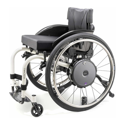
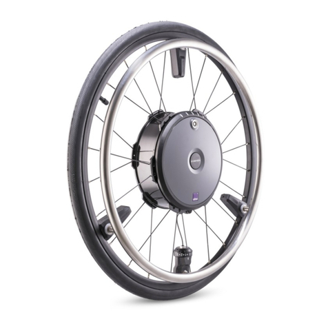
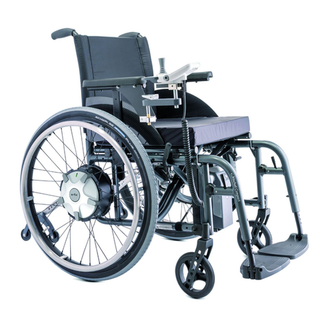
Alber E-MOTIONM12 User manual

Gebrauchsanweisung
Instructions d’utilisation
Manual de instrucciones
Istruzioni per l'uso
Brugsvejledning
Gebruiksaanwijzing
Bruksanvisning
Instruktionsbok
Operating Instructions
M 12
GB
F
D
E
I
DK
NL
N
S

5
11
15
7
3
1
2
12
4
3
8
9
10
6
14
13

Storage and Transportation
Protection of the Socket
Changing the Fuses
Recycling
Removing the wheels, transport
Signal Codes
Instructions for driving the e·motion
General instructions
Dangerous ground and dangerous sitations
Care
Maintenance
Care of batteries
Corrosion information
Service and Repair
Recycling
Warranty and Liability
Warranty
Liability
Index
1
2
3
3.1
3.2
3.3
4
5
6
6.1
6.2
7
7.1
7.2
8
9
9.1
9.2
4
5
6
6
6
6
8
9
12
12
12
12
13
14
14
15
15
15
9.3
9.4
9.5
9.6
10
11
12
12.1
12.2
13
13.1
13.2
13.3
14
15
16
16.1
16.2
17
16
16
16
17
17
19
20
20
21
22
22
22
23
23
24
24
24
24
25
Table of Contents
Delivery Package, Standard
Technical Data
Wheels
Holding Device for the Wheels
Delivery of Wheels and Batteries
Mounting the Wheels to the Wheelchair
Inserting the Batteries
Tilt Support
Operation
Turning On
Turning Off
Levels of Power
Power Survey
Sensitivity Control
Automatic Switch off
Batteries
Functions and Display
Charging the Batteries
1

· modular construction for easy and fast transport and
service
· user-friendly because of easily accessible elements such
as on/off switch, adjustment of the supporting power,
removal of the batteries, and of the wheels
We wish you a lot of fun and all the best with your e·motion,
your team
Dear wheelchair driver
With your decision to use the e·motion wheelchair power
by you got yourself a tangible glimpse of the future
and a great deal of personal mobility.
After the following brief information we will introduce you
to the e·motion and its functions, but first we would like
to explain the advantages of the system to you:
· absolutely noiseless technology, gearless and brushless
engine
· next to no maintenance
· the level of power that supports you and the driving
characteristics are individually adjustable to potential
physical handicaps
· superior steering electronics cater particularly to driving
a wheelchair
· driving downhill operates with electrically supported
breaking deceleration
· mountable to almost all types of wheelchairs with a wheel
size of 24“
2

3
wheelchair must be removed. In such cases retrofitting parking
brakes to the wheelchair is absolutely essential.
When transferring an occupant into or out of the wheelchair
the e·motion drive must be switched off and the parking
brakes applied. Under no circumstances may the push rims be
used to assist in transferring the occupant.
The e·motion is designed both for indoor and outdoor use.
Fundamentally, however, firm ground is a prerequisite for
operating the unit.
If a mobile phone or similar device is to be used, the e·motion
should provisionally be switched off on safe ground. Also travel
close to strong electric interference fields should be avoided.
Never use the e·motion before you participated
in the instruction session.
Important safety instructions
Please observe them closely!
In the interest of your safety, the e·motion may only be
operated by people who:
· have been taught how to use the e·motion
· are physically and mentally capable to use the e·motion in
all possible situations of employment
The instruction session is part of the delivery package. Your
local dealer or one of the distributors instructs you at
your convenience and no extra charge. If for some reason you
still do not feel comfortable handling the e·motion, please
contact your local dealer.
All the figures stated in the operating instructions provided
by the manufacturer of the wheelchair, in particular ones that
relate to the maximum obstruction heights, must be strictly
observed. Also the operating and safety instructions for the
wheelchair contained in the usage manual must be observed.
The e·motion wheels are not equipped with any independent
brakes. Consequently parking brakes must be fitted to the
wheelchair that can be adjusted to the e·motion wheels. In
order to operate the e·motion, any drum brakes fitted to the
4
1
Standard Delivery Package
· 2 powered wheels
· 2 batteries
· 2 protection covers for the batteries
· alber charger plus operating instructions
· 2 blade-type electric fuses 32 V, 15 A
· holding device already mounted on the wheelchair
· Operating instructions
Essential Parts
(please fold out the attached general drawing)
1 Holding ring
2 Battery
3 Wheel hub
4 Bow-type handle
5 Holding device
6 On/Off switch
7 Selection button
8 Socket
9 LED display
10 Charge capacity button
11 Sensor
12 Protection cover
13 Fuse box
14 Fuse 32 V, 15 A
15 Adjustment ring

10 kg
2 kg
12 km
2 x 150 W
24 V
2 x 24 V, 2 x 3,0 Ah
120 kg (observe the wheelchair manufacturer’s
specifications for this)
6 bar
for technical data, please consult its user’s manual
see wheelchair manufacturer’s specifications
Changes in technology and design due to constant
further development excepted.
2
Technical Data e·motion
Weight of the powered wheel:
Weight of the nickel metal hydrid battery:
Maximum range*:
Motor power:
Voltage:
Batteries:
Maximum weight added:
Pneumatic pressure:
charger BCS2402:
Maximum obstruction height:
* The battery range varies greatly and is predominantly
dependent on the quality of the driven surface on the driving
conditions. At optimum conditions (even surface, fully charged
batteries, motor power 50 %, temperature of 20 °C) the
indicated range can be reached.
The e·motion drive system serves to assist the wheelchair
driver in operating his manual wheelchair by providing him
with additional power. In particular, users with limited hand
and / or arm functionality can benefit from this drive system,
which can be individually tailored to the user. Consequently

it is also possible to pursue therapeutic goals with the e·motion.
The e·motion complies with the EU regulation for medical
products 93/42/EWG and 89/366/EWG electromagnetic
compatibility.
5

6
3
Wheels
3.1
Holding Device for the Wheels
To mount the e·motion to your wheelchair special holding
devices are necessary, which are mounted by or any
authorized dealer. These holding devices generally allow
the employment of the formerly used manual wheelchair wheels
as well as the use of the e·motion powered wheels.
3.2
Delivery of the Wheels and Batteries
Due to safety reasons wheels and batteries are separately
delivered. Thus you can mount the wheel immediately to the

wheelchair as described in the following paragraph.
We placed plastic protection covers (please see chapter 4) on
the batteries’ contact surfaces which you need to remove
according to the instructions delivered with the batteries.

Please keep these in a safe place because they are needed
furthermore for the transportation and storage of the batteries
(please see chapter 10).
1
2
3
4
3.3
Mounting the Wheels
Take any one of the e·motion wheels.
· In case the batteries [2] are
installed in the wheel.
Turn the holding ring [1]
counter clockwise and pull
the entire battery [2] out
of the wheel. Avoid touching
the contact surfaces at the
battery’s back side.
· Take the bow-type handle [4]
situated in the wheel hub [3]
out to 90°, which releases
the locking mechanism in
the axletree.

· Lock the wheel into place by
putting the bow-type handle
[4] back into its original
position.
·
Make sure the bow-type
handle [4]
is in its original
position and level
with the
rest of the surface.
· The wheel sits correctly in its
holding device [5] if it cannot
be removed without pulling out
the bow-type handle [4].
· Mount the second wheel accordingly.
Instructions for removing the wheels from the
wheelchair – see chapter 10
The e·motion wheel is now prepared to mount on the
wheelchair
Attention: never hold, shift or pull the wheel by
the bow-type handle [4] to avoid risk of fracture.
· Remove your wheelchair’s
wheel according to the

respective user’s manual
· Hold the e·motion wheel at
the wheel hub (as shown in
the picture on the right)
and insert it all the way
into the holding device [5]
on the wheelchair.
3
4
5
7

8
4
Inserting the Batteries
· Lock the wheelchair’s brakes
to avoid any movement of
the wheels.
· Make sure there is no foreign
matter such as pebbles,
pieces of metal etc. in the
wheel hub [3].
· Hold the battery [2] at its
holding ring [1].
· Please remove the plastic protection covers from the battery,
if you haven’t done so. Avoid touching the contact
surfaces (please see chapter 3.2).
· Insert the battery [2] all the way into the wheel hub [3]
(you hear a clicking sound as it catches).
· If you cannot insert the battery all the way, the wheel is
possibly not entirely in its holding device. Please see
chapter 3.
Attention: never force the battery
into the wheel hub!
· Insert the second battery [2] into the other wheel accordingly
· Release the wheelchair’s brakes.
It takes such little preparation to make your wheelchair ready
to use. Whether you want to activate the e·motion or not,
you can still move your wheelchair as usual manually. However,
you will notice that you will need a bit more physical power
as before.
1
2
3

9
5
Tilt Support
(available as optional accessory)
Before you use the e·motion for the first time,
you should make sure that your wheelchair is
equipped with tilt support!
In the interest of your safety, they should only be removed
to surmount an obstacle such as high curbs and the like. In
such case you need the help of an assisting person.
Since most wheelchairs come with tilt support, the tilt
support is available only as an optional accessory. It is mounted
at the plant or done by your authorized local dealer or
distributor, who must observe the included instructions
mounting the tilt support.
The tilt support adjusted to your wheelchair is mounted as
follows:
· First remove the quick pins [b] from the holding device
[d] by pressing your thumb on the center of the pin while
lifting it out with your middle and index finger (see
detail in the drawing)
· Insert the tilt support [c] into the holding device [a].
(The tilt support for the left side is marked with an “L“,
for the right with an “R“.)
a
c
b
b
a
b
a
c
b

10
· Secure the tilt support in the holding device [a] with the
quick pins [b]. Press the locking mechanism in the center
of the locking pin and push the pin entirely into the holding
device.
· Check whether the quick pins [b] securely rest in the holding
device [a]. You are not supposed to be able to remove them
without pressing the locking mechanism in their center.
· To remove the tilt support, work your way back step by step.
Driving the e·motion without attached tilt
support is not safe, thus not admissible.
The CE conformity for the e·motion is only valid in combination
with the tilt support.
In addition, the following points have to be taken in
consideration:
· Assembly and repairs as well as any other work done on the
e·motion must be carried out by Ulrich Alber GmbH or any
other personnel authorized by .
· The lower part of the tilt support must be attached high
enough so that their wheels can rotate freely when the
wheelchair is on a horizontal level.
· The user must pay particular attention to the following:
a) The tilt support must be unobstructed.
b) Please be extra careful when driving over obstacles
higher than 40 mm and narrower than the sidewalk’s curb.
c) The critical height of obstacles must be tested individually
for each wheelchair equipped with the e·motion and his/her
driver.
d) The point at which a certain wheelchair equipped with
the e·motion tilts backwards at its back axle must also be
tested by its user. The critical limit is reached at the point
where the tilted wheelchair falls backwards.
Important safety note
Due to blows or impact caused, for example, by unintentionally
setting down on too high kerbs, particularly the toothed
sections [d] in the anti-tipping supports may be subject to
above average loading. Consequently the condition of the
teeth (see illustration for the precise position) should be
checked at least once a week.
d
d

Swivel the anti-tipping supports as shown:
· Toothed section [d] sits tight within the holder [e] and the
adjusting tube [f] and cannot be twisted: anti-tipping
supports can continue to be used.
· Toothed section [d] can be twisted within the holder [e] or
the adjusting tube [f]: teeth are twisted – replace anti-
tipping supports immediately!
e
f
11
Condition of toothed sections
Undamaged teeth:
anti-tipping supports can continue to be used.
Teeth twisted:
replace anti-tipping supports immediately!

6
Operation
All of e·motion’s operation and service elements are housed
in its battery [2] and the wheel hub [3].
6.1
Turning on
· Depress the on/off switch [6]
for a moment; the e·motion is
switched on. You hear a beep
when the e·motion is on.
· Depending on the pre-
selected drive mode (see
chapter 7), one or two signal
tones follow.
6.2
Turning off
Briefly press the on/off switch [6]. You just hear a beep when
the e·motion is turned off.
12
7
Levels of Power
e·motion is equipped with two levels of power, which are
indicated by an acoustic signal. (Please see chart 7.1).
· Turn the e·motion on.
· To activate the desired level,
please press briefly the
selection button [7]. The
program automatically jumps
one step per keystroke.
Once you select a level, the e·motion remembers it even
after turning it off, i.e. restarting the e·motion you are on
the same level as you were before turning it off.
7
2
6
3

13
7.1
Power Survey
The level of power support can be selected
for each wheel and if necessary pre-selected
also.
Signal Motor performance Recommended being of use area Energy consumption
1 signal tone 50 % Mainly used indoors low, batteries saved,
longest range
2 signal tones 80 % Use in outside areas and for inclines, maximum increased consumption
braking available for declines

14
8
Automatic Switch Off
To save energy your e·motion is equipped with an automatic
switch off.
· The automatic switch-off is activated, when the drive is
switched on but not used for a period of 30 minutes.
An increase of the automatic switch-off time to 120 minutes
is possible and can be adjusted by your specialist dealer or
therapist.
· Due to the automatic switch
off a slight braking action is
activated for the period of 2
minutes. You can still move
the wheel, but it will take
more physical power.
· If you want to cancel the
automatic switch off during these 2 minutes, simply press
the on/off switch [6].
· After the two-minute slight braking action the e·motion
turns itself off completely.
· The automatic slight braking action is also activated for
2 minutes, if there is an abnormal occurrence before or
during the operation of the e·motion (please also see
chapter 11).
7.2
Sensitivity control
Your e·motion is equipped with two levels of power support
(see chart 7.1). Each level can be adjusted individually to
provide different power levels for the right or the left arm
respectively. This means that you need a higher or lower level
of power at the push rims to operate the e·motion.
Your therapist or your local dealer can adjust the level of
power you need at the adjustment ring. Please do not make
your own adjustments at the adjustment ring [15]. If the
wheels are adjusted differently, please mark them with stickers
“L“ (left) and “R“ (right) in order to put the wheels back on
the appropriate sides after e.g. transporting the wheelchair.
The setting of the sensitivity and the motor
parameter may be done exclusively by a
specialized authorized dealer or your therapist.
6

15
9
Batteries
9.1
Functions and Display
All the e·motion’s displays necessary for operation are located
on the battery [2].
You receive information concerning the charge of the batteries
by pressing the button [10]. The battery’s charge is displayed
on the LED display [9]. You read the LED display as follows:
· 2 green active LEDs:
60 -100 % charge capacity
· 2orange active LEDs:
20 -60 % charge capacity
· Red LED active:
20 % charge capacity
· 1 red LED flashes:
< 10 % charge capacity
Red light on:
At this point, stop your e·motion immediately
and recharge the batteries!
· When 10 % or less charge capacity is reached, 4 signals
sound every minute.
9.2
Charging the Batteries
· Please exclusively use the charger BCS2402A to charge
your batteries. The charger is part of the standard
delivery package.
· Push the battery charger plug into the socket [8] on each
of the two rechargeable batteries [2].
A connection is made when the marking (red ring) on the
charging plug is covered completely by the systemunit and
no longer visible.
· For instructions concerning the charging capacity and the
times it takes to charge the batteries, please consult the
charger’s user’s manual.
Both batteries are fully charged, when the green
battery charger LEDs are active.
Depending on the selected level of power of the respective
wheels, the batteries may run low at different times.
Please also see chapter 7.1. Due to security reasons you
should always turn off both batteries (even if one of
them is not low yet) and recharge both at the same time.
Temperature must be above 10 °C when charging the
batteries.
8
9
10
2

16
9.5
Changing the Fuses
· Carefully pull out the fuse
box [13] located on the side
of the battery until it locks.
· Take out the plugged in
blade-type fuse [14].
· Put in a new blade-type fuse [14].
· Push the fuse box [13] back into the battery [2].
· See whether the e·motion works by turning it on and
driving a short distance.
If you need to change the fuse once again shortly after, there
might be a malfunction in the system. In such case, please
contact your dealer.
9.3
Storage and Transportation
Except for transportation, you generally may leave the batteries
in the e·motion wheel at all times.
9.4
Protection of the Socket.
Whenever you do not use the
socket [8], cover it with the
plastic protection cover [12]
to avoid dampness from
entering into the socket.
Please see also chapter
3.2 and 4.
14
13
12

17
10
Removing the wheels, transport
Generally the e·motion wheels remain on the wheelchair at
all times. Only in case of transportation when the wheelchair
has to be folded, you need to take the wheels off. Please
follow these instructions:
· The following only applies to wheels which have different
selected power levels:
Indicate the right and left wheel as well as their respective
batteries with the stickers „R“ (right) and „L“ (left).
It is indispensable that you mount the respective wheels on
the correct side to have the individually selected
power level where you need it.
· Turn the holding ring [1]
counter clockwise pulling
the battery (2) out of the
wheels. Do the same at the
other wheel. Please avoid
touching the batteries’
contact surfaces.
9.6
Recycling
At the end of the batteries’ service life, or their dealers
take them back to recycle them appropriately.
1
2

18
Place the plastic protection covers on the batteries (please
see chapter 9.4).
· Take the bow-type handle [4]
situated in the wheel hub [3]
out to 90°, which releases
the locking mechanism within
the axletree.
· Take the wheel off the
wheelchair. Attention never
hold, pull or shift the wheel
by the bow-type handle [4]
to avoid risk of fracture.
· Take off the tilt support.
3
4
In order to avoid damaging the e·motion during
transport, please observe the following
instructions:
· Place the plastic protective covers provided on the
battery contact terminals.
· Never hold, pull or displace the wheel by its bow-type
handle [4].
· When removing the wheels do not hold them by the
push rims.
· Do not carry or transport the wheels by the push rims.
· Avoid overturning the wheels. Place them down carefully
and make sure that the push rims do not rest on each
other.
· To avoid damage during transportation, make sure that
the two wheels do not touch each other.
Table of contents
Other Alber Wheelchair manuals

Alber
Alber e-motion DuoDrive User manual

Alber
Alber twion User manual

Alber
Alber e-fix E35 User manual

Alber
Alber Viaplus User manual

Alber
Alber e-motion User manual

Alber
Alber E34z User manual

Alber
Alber e-motion M15 User manual

Alber
Alber twion T24 User manual

Alber
Alber E-Motion M25 Operating instructions

Alber
Alber E-Motion M25 User manual

Alber
Alber Twion Mobility Plus Paket User manual

Alber
Alber via GO V24 User manual

Alber
Alber viamobil V25 User guide

Alber
Alber ESPRIT User manual

Alber
Alber e-motion User manual

Alber
Alber twion User manual

Alber
Alber e-fix E35 User manual

Alber
Alber Adventure A10 Guide

Alber
Alber Adventure A10 User manual

Alber
Alber twion User manual