Alber Adventure A10 User manual

Adventure A10
Informationen für Therapeuten und Fachhändler
Adventure A10
Information for Therapists and DME Dealers
Adventure A10
Informazioni per i terapisti e rivenditori
D
F
I
Adventure A10
Informations pour les thérapeutes et les
commerçants spécialisés
GB/US
Neu! Auflage
New! Edition
Noveau! Edition
Nuovo! Edizione
3
AB_Therap_A10_U1-4_02012008.indd1 1 02.01.2008 13:24:03 Uhr

D
F
I
Adventure A10
Informationen für Therapeuten und Fachhhändler
Adventure A10
Information for Therapists and DME Dealers
Adventure A10
Informations pur les thérapeutes et les
commerçants spécialisés
Adventure A10
Informazioni per i terapisti e rivenditori
GB/US
AB_Therap_A10_U1-4_02012008.indd3 3 02.01.2008 13:24:04 Uhr

2
Contents
1 Mechanical adjustments to the adventure
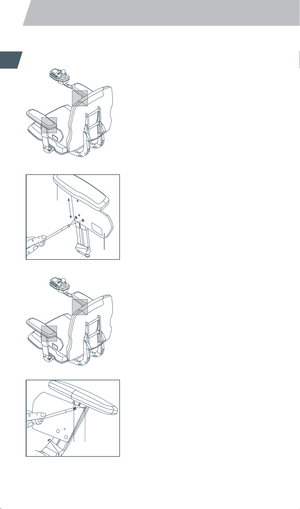
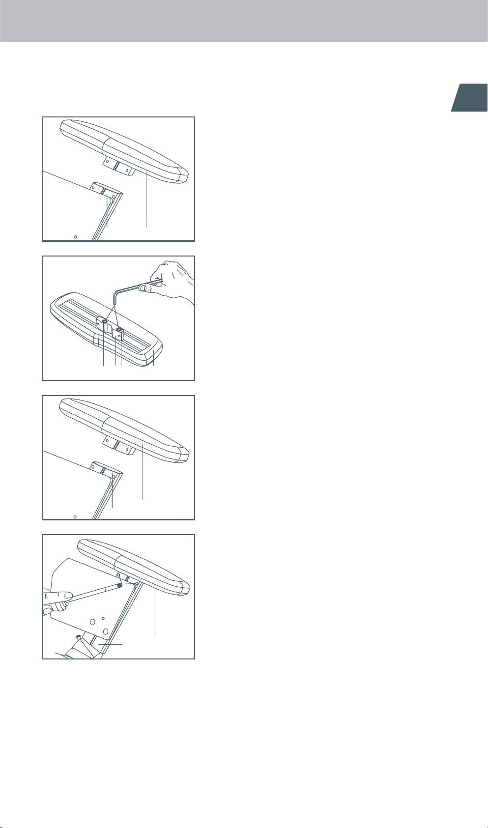
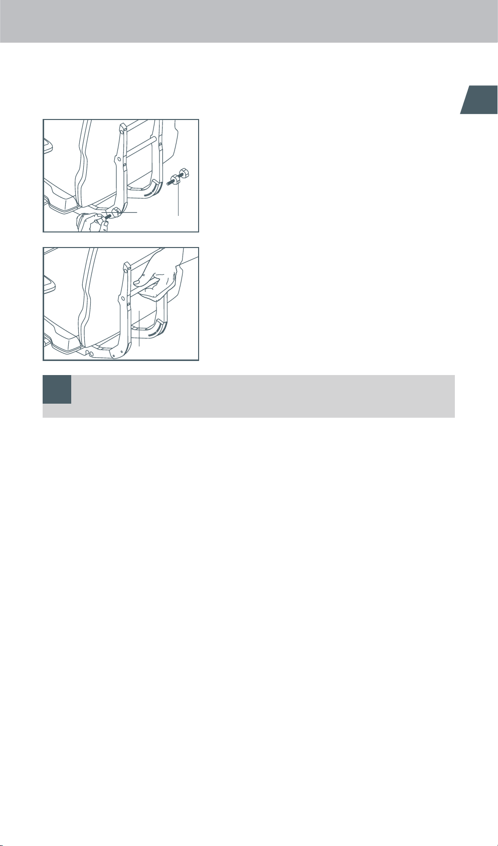
1.1 Armrest height adjustment 4
1.2 Armrest length adjustment 4
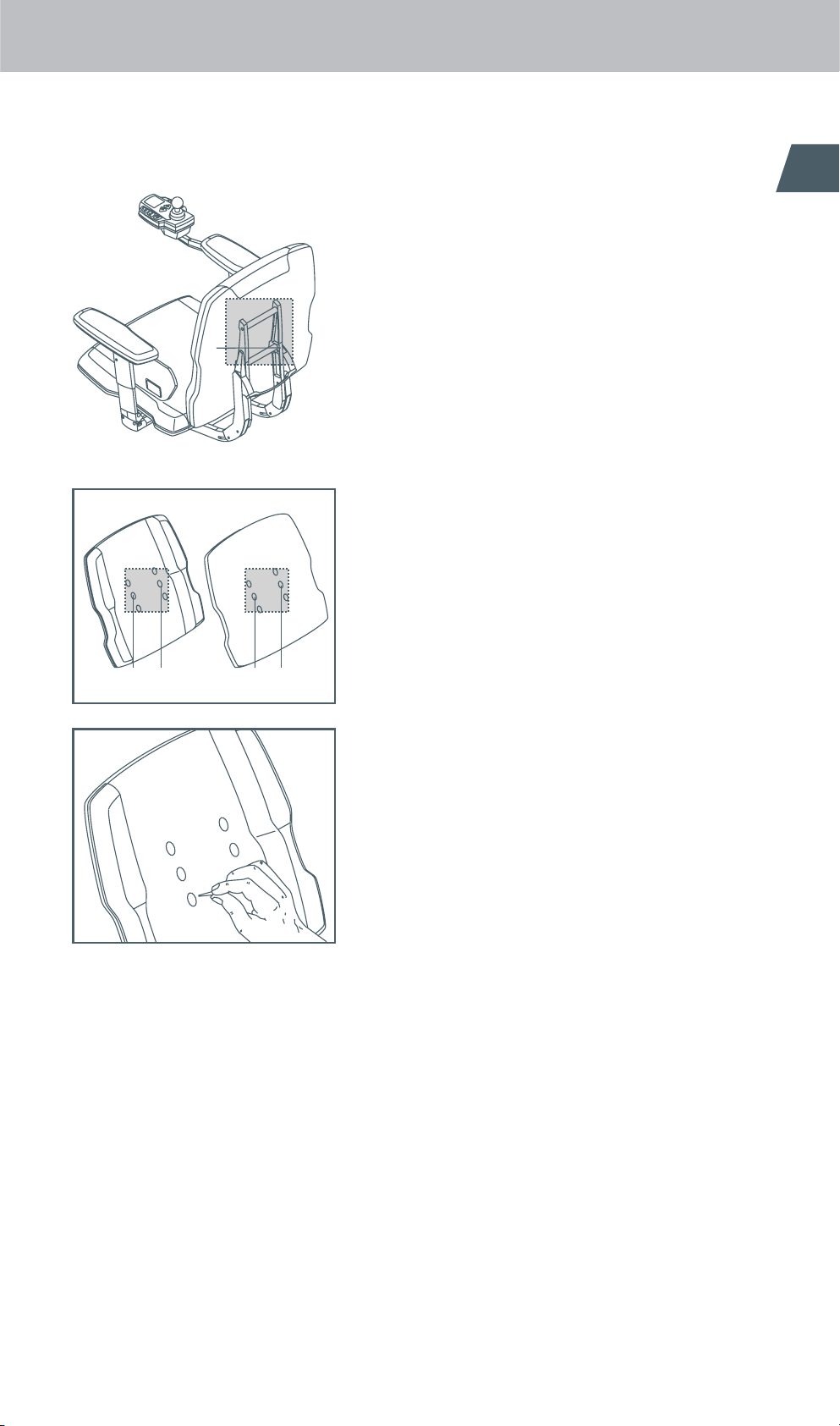
1.3 Armrest sideways adjustment 6
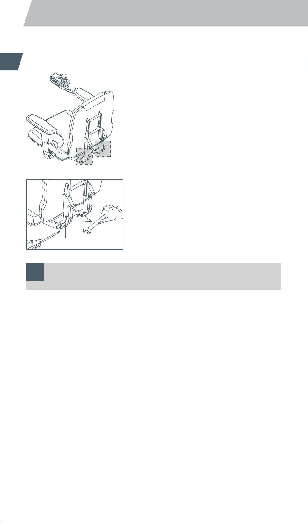
1.4 Backrest height adjustment only function seat
(comfortand standard upholstery) 7
1.5 Backrest angle of inclination adjustment
Functionseat 8
1.6 Backrest angle of inclination adjustment
Standardseat 9
1.7 Seat length adjustment
Functionseat (standard and comfort upholstery) 10
1.8 Leg support angle adjustment
Functionseat 11
1.9 Leg support length adjustment
Standardand function seats 12
1.10 Leg support footrest angle adjustment
Functionseat 13
1.11 Leg support footrest length adjustment
Standardand function seats 14
1.12 Interface instructions 15
1.13 Adjusting the chassis springing and damping 16
1.13.1 General information 16
1.13.2 Adjusting the rear springing 17
1.14 Setting the direction indicators 18
1.15 Setting the seat position
Functionseat 19
1.16 Setting the seat position
Standardseat 20
1.17 Fitting mudguards (optional extra) 21
1.17.1 Mudguards for the steering wheels 21
1.17.2 Mudguards for the powered wheels 22
1.17.3 Fitting rear reflectors 22
1.18 Control unit length adjustment 23
2 Settings on the control unit
2.1 General information regarding
programmingmode 24
2.2 Driving programs 24
2.3 Changeable parameters 25
2.4 Activating service mode 28
2.5 Selection of the parameter settings
Indoor/Outdoor 29
2.6 Changing the parameters 30
2.7 Reverting to factory parameters settings 31
2.8 Parameter table 32
2.8.1 adventure Version 6 km/h 32
2.8.2 adventure Version 10 km/h 33
2.8.3 adventure Version 12 km/h 34
2.9 Fault detection / fault analysis codes 35
2.10 Fault indications on the display 35
AB_Therap_A10_GB_ms.indd 1 02.01.2008 11:40:28 Uhr

3
Contents
General notes
For the work procedures described in this information
bulletin you will need a set of hexagon socket keys
(Allen keys) 2.5 to 8 mm.
Ordering information for spare parts can be found in our
product manual.
alber offers specialist dealers for medical accessories
training courses for repairing the adventure and other alber
products.
Standard seat
The adventure wheelchair is now equipped with the functio-
nal or Recaro (optional) seating system and no longer with
the standard seat.
The information on the standard seat contained in this
brochure only refers to possible adjustments to the
adventure wheelchairs that are still equipped with the stan-
dard seat.
AB_Therap_A10_GB_ms.indd 2 02.01.2008 11:40:29 Uhr

4
1 Mechanical adjustments to the adventure
1.1 Armrest height adjustment
– Loosen the two screws [1] located in the side support.
– Push the armrest [2] to the desired height.
– Tighten the two screws [1] again.
1.2 Armrest length adjustment
– Loosen and remove the two screws [3] located in the side
support under the upholstery.
1
2
3
3
AB_Therap_A10_GB_ms.indd 3 02.01.2008 11:40:41 Uhr

5
1 Mechanical adjustments to the adventure
– Pull the armrest [2] completely out of the holder [4].
– Loosen the two screws [6] located underneath the
upholstery[5].
– Push the moveable part [7] to the desired position.
– Tighten the two screws [6] again.
– Push the armrest [2] back into the holder [4].
– Screw the armrest [2] back onto the side support [8].
Õ
2
4
5
7
66
Õ
2
4
2
8
AB_Therap_A10_GB_ms.indd 4 02.01.2008 11:40:46 Uhr

6
!
1.3 Armrest sideways adjustment
– Tilt the entire seat [9] forwards.
– Loosen the two screws [10] located under the seat.
– Push the complete armrest [2] into the desired position.
– Tighten the two screws [10] again.
– Fold the seat carefully back down onto the chassis.
Checkthe position of the armrest [2] in relation to the
direction indicators.
If the armrest bumps into the direction indicators, then
they will have to be adjusted too (see chapter 1.14).
9
Õ
210
Õ
AB_Therap_A10_GB_ms.indd 5 02.01.2008 11:40:52 Uhr

7
1.4 Backrest height adjustment
Only Function seat (comfort and standard
upholstery)
– Remove the cushion from the backrest.
– Loosen and remove the 4 screws that hold the backrest to
the support bracket [11].
– On the inside of the backrest there are 3 holes in each of
two rows which are normally covered by the upholstery.
Feel for these holes with a sharp object.
– Select the hole [12] which will provide the desired height
for the backrest.
– With a sharp knife, cut an opening into the upholstery over
the chosen holes.
– As an alternative to a knife a soldering iron may also be
used. When the screw holes melt it should leave an even,
clean and heat-sealed border around the holes.
– Screw the backrest back onto the support bracket [11] in
the height position you have selected.
– Replace the cushion on the backrest.
11
1212 1212
AB_Therap_A10_GB_ms.indd 6 02.01.2008 11:40:58 Uhr

8
!
1.5 Backrest angle of inclination adjustment
Function seat
– Loosen the screws [13] in the support bracket.
– Push the entire backrest [14] to the desired angle of
inclination.
– Tighten the screws [13] again.
By adjusting the angle of inclination, the height of the
backrest is also altered. It may be necessary to re-set the
height (see chapter 1.4).
1313
11
14
AB_Therap_A10_GB_ms.indd 7 02.01.2008 11:41:04 Uhr

9
!
1.6 Backrest angle of inclination adjustment
Standard seat
– Loosen and remove the four star grips [15].
– Pull or push the backrest [14] to the desired position.
– Screw the four star grips [15] back in and tighten them.
By adjusting the angle of inclination, the height of the
backrest is also altered. It may be necessary to re-set the
height (see chapter 1.4).
15
14
14
Õ
AB_Therap_A10_GB_ms.indd 8 02.01.2008 11:41:07 Uhr

10
1.7 Seat length adjustment
Function seat (standard and comfort
upholstery)
– Pull the cushion off the seat.
– Loosen and remove the four screws holding the seat.
– On the inside of the seat there are 5 holes in each of two
rows which are normally covered by the upholstery.
Feelfor these holes with a sharp object.
– Select the hole [16] which will provide the desired seat
length for you.
– With a sharp knife, cut an opening into the upholstery over
the chosen holes.
– As an alternative to a knife a soldering iron may also be
used. When the screw holes melt it should leave an even,
clean and heat-sealed border around the holes.
– Screw the seat back on in the position you have selected.
– Replace the cushion on the seat.
16 16
AB_Therap_A10_GB_ms.indd 9 02.01.2008 11:41:11 Uhr

11
1.8 Leg support angle adjustment
Function seat
– Remove the leg support from the seat.
– Loosen the two screws [17] on the top of the leg support.
The connecting piece [18] is now freely moveable.
– Set the desired angle.
– Tighten the two screws [17] again.
– Attach the leg support back onto the seat.
17
Õ
Õ
17
18
AB_Therap_A10_GB_ms.indd 10 02.01.2008 11:41:14 Uhr

12
1.9 Leg support length adjustment
Standard and function seats
– Loosen the two screws [19] at the back of the leg support.
– Pull or push the lower part of the leg support [20] into the
desired position.
– Firmly tighten the two screws [19] again.
19
20
Õ
Õ
AB_Therap_A10_GB_ms.indd 11 02.01.2008 11:41:19 Uhr

13
1.10 Leg support footrest angle adjustment
Function seat
– Loosen the screws [21] on both sides at the lower end of
the leg support.
– Push the retainer [22] into the desired position.
– Check the retainer and with it the angle of the footrest.
Ifnecessary, the retainer [22] may have to be moved again.
– If the retainer and with that the desired angle of the foot-
rest are set correctly, then tighten the screws [21] again.
21
22 22
Õ
Õ
AB_Therap_A10_GB_ms.indd 12 02.01.2008 11:41:23 Uhr

14
1.11 Leg support footrest length adjustment
Standard and function seats
– Loosen the three screws [23] underneath the footrest.
– The length can be adjusted by inserting the screws in one
of the three sets of holes A, B or C.
– Screw the footrest [24] into the desired position.
232323
A
B
C
24
Õ
Õ
AB_Therap_A10_GB_ms.indd 13 02.01.2008 11:41:25 Uhr

15
1.12 Interface instructions
The interface [25] located on the chassis is for the
attachment of a peripheral module for the control of external
drives.
The cover [26] prevents the interface getting dirty or
damaged and must only be removed if a device is to be
attached.
Õ
26
25
Õ
AB_Therap_A10_GB_ms.indd 14 02.01.2008 11:41:30 Uhr

16
Feder
(blau, schwarz oder rot)
Dämpferelement
1.13 Adjusting the chassis springing and
damping
1.13.1 General information
When the adventure is first delivered, the chassis is optimally
adjusted to the respective weight of the user and, as a rule,
does not need any further adjustment. If a second-hand
device is to be used or the body weight of the wheelchair
driver should change significantly, then the chassis should
be readjusted.
The spring hardness is principally responsible for the degree
of comfort of the chassis and should be selected to match the
weight of the wheelchair driver. Basically there are three
different degrees of spring hardness available for the respec-
tive weight categories:
Blue springs:
Wheelchair drivers with up to 80 kg body weight
Black springs:
Wheelchair drivers with from 81 to 120 kg body weight
Red springs:
Wheelchair drivers with from 121 to 140 kg body weight
Determine into which weight category the wheelchair driver
falls and whether the colour of the installed springs corres-
ponds. Under some circumstances the springs will have to be
exchanged or readjusted. This must only be undertaken by
an authorised and trained dealer or by the alber Service Cen-
ter (phone +49 (0) 800 90 96 250).
The rear springs are principally responsible for the comfort
of the ride and they can be finely set thanks to the adjustab-
le spring preload. The front springs need to be readjusted
only in rare cases (spring replacement necessary, significant
weight change of the wheelchair driver) and should, as a rule,
remain in the position set in the factory.
Spring
(blue, black or red)
Damping
element
AB_Therap_A10_GB_ms.indd 15 02.01.2008 11:41:31 Uhr

17
!
!
1.13.2 Adjusting the rear springing
Prior to adjusting the springing the batteries must be
removed (see illustration) so that the spring/damper element
is completely load-free.
The preload of the rear springs [27] can be set with the help
of several differently coloured spacer gauges that can be
obtained from alber or with a conventional one.
– Place the spacer gauge [28] against the spring [27] as
shown in the diagram.
Thespacer gauge [28] must make contact with the spring
buffer [29].
– Turn the adjusting wheel [30] on the spring.
– You have set the correct spacing, as taken from the table
below, when the adjustment wheel [30] makes contact with
the spacer gauge.
Make sure that you set the same figure for both rear
springs.
The maximum additional load of 140 kg should never be
exceeded.
Spacer gauge
Identifier:
blue (for blue springs)
To 50 kg 84 mm
To 60 kg 83 mm
To 70 kg 82 mm
To 80 kg 80 mm
Identifier:
black (for black springs)
To 90 kg 83 mm
To 100 kg 81 mm
To 110 kg 79 mm
To 120 kg 77 mm
Identifier:
red (for red springs)
To 130 kg 79 mm
To 140 kg 77 mm
Please inform the wheelchair occupant that a readjust-
ment of the front* and rear suspensions will be necessary
if he or she gains or loses substantially in weight (for
example, due to a particular illness).
If the user gains a large amount of weight there is a danger
that the chassis may be damaged; if there is a large loss in
weight the comfort during driving is reduced.
* To carry out installation work and adjustments to the front
part of the chassis, prior training by alber is a prerequisite.
Please contact us for this.
27
30
28
29
back
front
AB_Therap_A10_GB_ms.indd 16 02.01.2008 11:41:35 Uhr

18
1.14 Setting the direction indicators
When the armrest is adjusted sideways (see chapter 1.3), it
may prove necessary to re-position the two direction
indicators [31].
– Loosen the two screws [32].
– Pull or push the direction indicator [31] into the desired
position. There should always be a small space
(approx.5 mm) between the direction indicator [31] and
armrest.
– Tighten the two screws [32] again.
31 32
Õ
Õ
31
31
AB_Therap_A10_GB_ms.indd 17 02.01.2008 11:41:35 Uhr

19
1.15 Setting the seat position
Function seat
– Loosen the screws [34] on both sides of the holder stay
[33].
– Pull or push on the holder stay [33] so that the entire seat
holder moves into the desired position.
– Firmly tighten the two screws [34] on both sides of the
holder stay [33] again.
3334
AB_Therap_A10_GB_ms.indd 18 02.01.2008 11:41:36 Uhr
Other manuals for Adventure A10
3
Table of contents
Other Alber Wheelchair manuals

Alber
Alber viamobil Series User manual

Alber
Alber twion T24 User manual

Alber
Alber E-Motion M25 User manual

Alber
Alber Viaplus User manual

Alber
Alber via GO V24 User manual

Alber
Alber viamobil eco V14 User manual

Alber
Alber e-fix E35 User manual

Alber
Alber e-fix E35 User manual

Alber
Alber Scalacombi Eco User manual

Alber
Alber E-Motion M25 User manual

Alber
Alber Adventure A10 Guide

Alber
Alber viamobil V15 User manual

Alber
Alber e-motion M15 User manual

Alber
Alber e-fix User manual

Alber
Alber viamobil User manual

Alber
Alber E34z User manual

Alber
Alber viamobil V15 User manual

Alber
Alber twion User manual

Alber
Alber e-fix User manual

Alber
Alber e-fix User manual