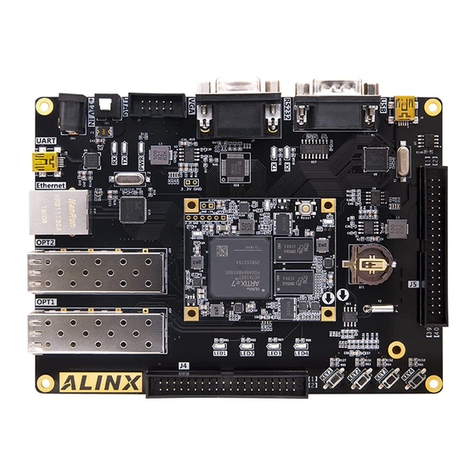
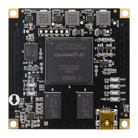
Alinx AX301 User manual

ALINX FPGA BOARD
AX301
User Manual

2 / 23
AX301 User Manual
Http://www.alinx.com.cn
2 / 23
Revsion History
Revision
Description
1.0
First Release

3 / 23
AX301 User Manual
Http://www.alinx.com.cn
3 / 23
Copyright Notice:
Copyright ©2018 by ALINX Technologies inc. All rights are reserved.
Development Environment:
Quartus 17.1 is from Xilinx website
https://www.altera.com
Official website:
Http://www.alinx.com.cn
E-mail:
Tel:
+86-021-67676997
WeChat public number:
ALINX-HEIJIN

4 / 23
AX301 User Manual
Http://www.alinx.com.cn
4 / 23
Contents
1. Overview.........................................................................................................................................5
2. Power..............................................................................................................................................6
3. FPGA..............................................................................................................................................7
3.1 JTAG..........................................................................................................................................8
3.2 Power and GND.........................................................................................................................8
4. 50M Crystal ....................................................................................................................................9
5. SPI Flash.......................................................................................................................................10
6. SDRAM........................................................................................................................................11
7. EEPROM......................................................................................................................................12
8. RTC...............................................................................................................................................13
9. USB TO UART.............................................................................................................................14
10. VGA PORT...................................................................................................................................15
11. SD CARD SLOT..........................................................................................................................17
12. LED...............................................................................................................................................17
13. KEY..............................................................................................................................................18
14. CAMERA PORT...........................................................................................................................19
15. Digital Tube ..................................................................................................................................19
16. BUZZER.......................................................................................................................................21
17. Expansion port..............................................................................................................................22

5 / 23
AX301 User Manual
Http://www.alinx.com.cn
5 / 23
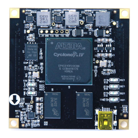
This development board is an entry-level product of ALTERA FPGA, mainly for FPGA
beginners, model EP4CE6F17C8, is a 256-pin FBGA package. The development of the
entire development board is practical, there are two 40-pin 2.54 standard expansion port, a
total of 68 IO, in addition to retain the 5V power supply, 3.3V power supply, there are
multiple GND, for the likes of DIY players, is a very Good choice. In addition, many
supporting modules can also be directly connected to the expansion port of this FPGA
development board, such as ADDA module, 4.3’TFT screen, audio modules, cameras, etc.,
to provide players with more choices for learning. Here we will make a detailed introduction
to this development board.
1. Overview
Here is a brief introduction to this FPGA development platform. This development board
uses ALTERA's Cyclone IV series FPGA, model EP4CE6F17C8, 256-pin FBGA package.
The resources of this FPGAare shown in Table 1-1:
parameter
value
Logic elements(LEs)
6272
Embedded memory(Kbits)
270
Embedded 18x18multipliers
15
PLLs
2
Global Clock Networks
10
Kernel voltage
1.2V
Work temperature
0-85℃
Table 1-1

6 / 23
AX301 User Manual
Http://www.alinx.com.cn
6 / 23
The structure of the entire system is shown in Figure 1-1.
FPGA
EP4CE6
256Mbit
SDRAM
50M
晶振 EEPROM
24LC04
实时时钟
蜂鸣器
CP2102
复位键 按键1按键2按键3
Micro
SD卡座
VGA接口
JTAG口摄像头
接口
40针扩展口(34个IO口,1路5V,2路3.3V,3路GND
电源
开关
USB供电接
口及串口
电池座
6位数码管 4个用户LED灯
2路电源转换芯片
16Mbit
FLASH
40针扩展口(34个IO口,1路5V,2路3.3V,3路GND
Figure 1-1
Through this diagram, we can see the functions that this development platform can achieve.
- USB interface power supply, while USB to serial port function.
- 1 large-capacity 256Mbit SDRAM, which can be used as data cache.
- 1 16Mbit SPI FLASH that can be used to store FPGAconfiguration files and user data;
- 1 camera interface, can connect OV5640 camera.
- 1 VGA port, 16-bit VGA port, can display 65536 colors, can display color pictures and
other information.
- 1 RTC real-time clock with battery holder, battery model CR1220.
- 1 piece IIC interface EEPROM 24LC04.
- 4 red LEDs for water flow function.
- 4 buttons, a reset button, 3 user buttons.
- 50M crystal oscillator to provide a stable clock source to the development board.
- Two 40-pin black gold standard AX expansion ports (2.54mm pitch), of which 34 IO ports,
1 5V power supply, 2 3.3V power supplies, 3 GND. Two expansion modules can be
connected at the same time, such as 4.3-inch TFT module andAD/DA module.
- The JTAG port is reserved for debugging and solidifying the FPGA.
- 1 Micro SD slot with SPI mode support.
- A 6-bit digital tube, 6-digit dynamic display.
2. Power
The AX301 development board is powered by USB, and the MINI USB cable is used to
connect the development board with the USB of the computer. Pressing the power switch
will not only supply power to the development board. The power supply design Figure 2-1
on the development board is as follows:

7 / 23
AX301 User Manual
Http://www.alinx.com.cn
7 / 23
USB POWER
PORT
FUSE
AMS1117-
3.3
AMS1117-
1.2V
3.3V
1.2V
SWITCH
J1
F1
SW1
U1
U5
AMS1117-
2.5
2.5V
U6
Figure 2-1
The development board is powered by USB and generates three power supplies of +3.3V,
+2.5V, and +1.2V through the 3 LDO power chip, respectively, to meet the BANK voltage
and core voltage of the FPGA.
When designing the PCB, we use a 4-layer PCB, leaving an independent GND plane,
which allows the entire development board to have a complete ground plane, ensuring that
the development board has very good stability. On the PCB, we set aside test points for
each power supply so that the user can confirm the voltage on the board.
3. FPGA
The FPGA model is EP4CE6F17C8, which belongs to ALTERA Cyclone IV. This model is
BGA package, 256 pins. The pin names are in the form of letter + number, such as E3, G3,
etc. When we look at the schematic, we see the letter + number in this form, which
represents the pins of the FPGA. Figure 3-1 shows the FPGA chip physical map used for
the development board.
Figure 3-1

8 / 23
AX301 User Manual
Http://www.alinx.com.cn
8 / 23
3.1 JTAG
First of all ,we talk about FPGA configuration and debugging interface: JTAG interface.
The function of the JTAG interface is to download the compiled program (.sof) to the
FPGA or download the FLASH configuration program (.jic) to the SPI FLASH.After the
sof file is downloaded to the FPGA, it will be lost after power-off ,so we need to download
it again after the power-on. At this time, we can use the Quartus software to convert the sof
file into a jic file.After downloading the jic file to the development board's FLASH via
JTAG, it will not be lost after power-off. After the power-on, the FPGA will read the jic
configuration file in the FLASH and run.
Figure 3-2 shows the schematic part of the JTAG port, which involves the four signals
TCK, TDO, TMS, and TDI. These four signals are directly derived from the FPGA pins.
Each signal has a diode overvoltage protection circuit on the development board.
Figure 3-2
3.2 Power and GND
The power supply pin portion of the FPGAincludes each bank's power pin, core voltage pin,
analog voltage, and phase-locked loop power supply pin. VCCINT is the FPGA core power
supply pin, which is connected to 1.2V; VCCIO is for each BANK of the FPGA. Power
supply voltage, where VCCIO0 is the power supply pin of the BANK0 of the FPGA.
Similarly, VCCIO1~VCCIO3 are power supply pins of the BANK~BANK3 of the FPGA
respectively. In the development board, VCCIO is connected to 3.3V voltage, that is to say,
this The development board FPGA pins are 3.3V inputs and outputs. VCCA is the FPGA
analog supply pin, followed by 2.5V, VCCD_PLL is the FPGAPLL power supply pin, also
connected to 1.2V, FPGA power supply connection diagram shown in Figure 3-3.

9 / 23
AX301 User Manual
Http://www.alinx.com.cn
9 / 23
Figure 3-3
In addition, there are many pins in the FPGA that need to be connected to GND to ensure a
stable reference ground within the FPGA. The GND connected to the FPGA is shown in
Figure 3-4.
Figure 3-4
4. 50M Crystal
Figure 4-1 is the 50M active crystal circuit that we mentioned above to provide the clock
source for the development board. The crystal oscillator output is connected to the FPGA's
global input clock pin (CLK1 pin E1). This CLK1 can be used to drive the user logic within
the FPGA. The user can configure the FPGA's internal PLL (phase-locked loop) to achieve

10 / 23
AX301 User Manual
Http://www.alinx.com.cn
10 / 23
frequency division and frequency multiplication. Other frequency clocks.
Figure 4-1
Clock pin assignment:
Signal Name
Pin
CLK
E1
5. SPI Flash
The development board uses a 16Mbit-sized SPI FLASH chip, M25P16, which uses the
3.3V CMOS voltage standard and completely replaces the ALTERA configuration chip
EPCS16. Because of its non-volatile nature, SPI FLASH can be used as the boot image of
an FPGA system. These images mainly include FPGA JIC configuration files, soft core
application code, and other user data files.
SPI FLASH specific models and related parameters are shown in Table 5-1。
Position
Model
Capacity
Factory
U8
M25P16
16M bit
ST
Table 5-1
The SPI Flash schematic is shown in Figure 5-1.
Figure 5-1

11 / 23
AX301 User Manual
Http://www.alinx.com.cn
11 / 23
Configure chip pin assignment:
Signal Name
Pin
DCLK
H1
nCSO
D2
DATA0
H2
ASDO
C1
6. SDRAM
The development board contains a SDRAM chip, model: HY57V2562GTR, capacity:
256Mbit (16M*16bit), 16bit bus. SDRAM can be used for data cache, such as data collected
by the camera, temporarily stored in SDRAM, and then displayed through the VGAinterface.
This SDRAM is used for data caching.
The SDRAM hardware connection is shown in Figure 6-1.
Figure 6-1
SDRAM pin assignment:
Signal Name
Pin
S_CLK
B14
S_CKE
F16
S_NCS
K10
S_NWE
J13
S_NCAS
J12
S_NRAS
K11

12 / 23
AX301 User Manual
Http://www.alinx.com.cn
12 / 23
S_DQM<0>
J14
S_DQM<1>
G15
S_BA<0>
G11
S_BA<1>
F13
S_A<0>
F11
S_A<1>
E11
S_A<2>
D14
S_A<3>
C14
S_A<4>
A14
S_A<5>
A15
S_A<6>
B16
S_A<7>
C15
S_A<8>
C16
S_A<9>
D15
S_A<10>
F14
S_A<11>
D16
S_A<12>
F15
S_DB<0>
P14
S_DB<1>
M12
S_DB<2>
N14
S_DB<3>
L12
S_DB<4>
L13
S_DB<5>
L14
S_DB<6>
L11
S_DB<7>
K12
S_DB<8>
G16
S_DB<9>
J11
S_DB<10>
J16
S_DB<11>
J15
S_DB<12>
K16
S_DB<13>
K15
S_DB<14>
L16
S_DB<15>
L15
7. EEPROM
The board contains a EEPROM, model 24LC04, with a capacity of 4Kbit (2*256*8bit) and
consists of two 256-byte blocks that communicate through the IIC bus. On-board
EEPROM is to learn IIC bus communication. EEPROM is generally used in the design of
instruments and meters, and used as a storage of some parameters, and power loss is not

13 / 23
AX301 User Manual
Http://www.alinx.com.cn
13 / 23
lost. This kind of chip is simple to operate and has a very high price/performance ratio.
Therefore, although the capacity ratio is high, the price is very low, which is a good choice
for products that require high costs. Figure 7-1 shows the EEPROM schematic.
Figure 7-1
EEPROM pin assignment:
Signal Name
Pin
SDA
E6
SCL
D1
8. RTC
The board contains a real-time clock RTC chip, model DS1302, whose function is to
provide calendar functions up to 2099. There are days, minutes, seconds and weeks. If the
system requires time, RTC needs to be involved in the product. He needs a 32.768KHz
passive clock externally to provide an accurate clock source to the clock chip so that RTC
can accurately provide clock information to the product.At the same time, in order to
power down the product, the real-time clock can still operate normally. Generally, a battery
is needed to power the clock chip. In figure 9-1, U10 is the battery holder. After we put the
button battery (model CR1220, voltage is 3V) into the battery, When the system loses the
battery, the button battery can also supply power to the DS1302. In this way, regardless of
whether the product is powered or not, the DS1302 will operate normally and will not be
interrupted, providing continuous time information. Figure 8-1 shows the DS1302
schematic.

14 / 23
AX301 User Manual
Http://www.alinx.com.cn
14 / 23
Figure 8-1
DS1302 pin assignment:
Signal Name
Pin
RTC_SClK
P16
RTC_nRST
N8
RTC_DATA
M8
9. USB TO UART
The development board includes the USB-UAR chip of Silicon Labs CP2102GM. The
USB interface uses the MINI USB interface. This USB interface implements the power
supply function. There is a USB-to-serial port function that can be connected to the PC
using a USB cable. USB port for serial data communication.
The schematic of the serial port is shown in Figure 9-1.
Figure 9-1

15 / 23
AX301 User Manual
Http://www.alinx.com.cn
15 / 23
At the same time, two LED indicators (LED7, LED8) are set for the serial port signal.
LED7 and LED8 will indicate whether the serial port has data to send or if there is data
accepted, as shown in Figure 9-2.
Figure 9-2
UART pin assignment:
Signal Name
Pin
RXD
M2
TXD
N1
10.VGA Port
The VGA interface is a type D interface with a total of 15 pinholes, divided into three rows,
five in each row. Three RGB color component signals and two scanning synchronization
signals HSYNC and VSYNC pins.
The pins 1, 2, and 3 are three-color analog voltages of red, green, and blue, which are
0~0.714V peak-peak, 0V represents colorless, and 0.714V represents full color. Some
non-standard monitors use a 1Vpp full-color level.
The source impedance and termination resistance of the three primary colors are all 75
ohms. As shown in Figure 10-1
Figure 10-1
HSYNC and VSYNC are line data synchronization and frame data synchronization,
respectively, TTL level. The FPGA can only output digital signals, whereas the R, G, and B
required by the VGA are analog signals, and the digital to analog signals of the VGA are
implemented through a simple resistor circuit. This resistor circuit can generate 32
gradient-level red and blue signals and 64 gradient-level green signals (RGB 5-6-5). The
VGA interface circuit is shown in Figure 10-2.

16 / 23
AX301 User Manual
Http://www.alinx.com.cn
16 / 23
Figure 10-2
VGA pin assignment:
Signal Name
Pin
Explain
VGA_D[0]
C3
BLUE[0]
VGA_D[1]
D4
BLUE[1]
VGA_D[2]
D3
BLUE[2]
VGA_D[3]
E5
BLUE[3]
VGA_D[4]
F6
BLUE[4]
VGA_D[5]
F5
GREEN[0]
VGA_D[6]
G5
GREEN[1]
VGA_D[7]
F7
GREEN[2]
VGA_D[8]
K8
GREEN[3]
VGA_D[9]
L8
GREEN[4]
VGA_D[10]
J6
GREEN[5]
VGA_D[11]
K6
RED[0]
VGA_D[12]
K5
RED[1]
VGA_D[13]
L7
RED[2]
VGA_D[14]
L3
RED[3]

17 / 23
AX301 User Manual
Http://www.alinx.com.cn
17 / 23
VGA_D[15]
L4
RED[4]
VGA_HS
L6
Line synchronization signal
VGA_VS
N3
Field synchronization signal
11.SD Card Slot
SD card is a very common storage device nowadays. The SD card that we have expanded
supports SPI mode. The SD card used is a MicroSD card. The schematic is shown in Figure
11-1.
Figure 11-1
SD card slot pin assignment:
SD Mode
Signal Name
Pin
SD_NCS
D11
SD_DIN
F10
SD_CLK
D12
SD_DOUT
E15
12.LED
The board contains 4 user LED light-emitting diodes. The schematic diagram of the four
user LED is shown in Figure 12-1. When the pinout of the FPGAis logic 0, the LED goes out.
When the output is logic 1, the LED is lit.

18 / 23
AX301 User Manual
Http://www.alinx.com.cn
18 / 23
Figure 12-1
LED pin assignment:
Signal Name
Pin
LED0
E10
LED1
F9
LED2
C9
LED3
D9
13.KEY
The board contains 4 independent buttons, 3 user buttons (KEY1~KEY1), and 1 function
button (RESET). The buttons are all low pressed as low level (0) and released as high level
(1). The schematic of the 4 buttons is shown in Figure 13.1.
Figure 13-1
Key pin assignment:
Signal Name
Pin
Pin Name
RESET
N13
RESET
KEY1
M15
KEY 1
KEY2
M16
KEY 2
KEY3
E16
KEY 3

19 / 23
AX301 User Manual
Http://www.alinx.com.cn
19 / 23
14.Camera Port
The development board contains an 18-pin CMOS camera interface that can be connected
to the camera module to enable video capture. After the capture, the display can be
connected via a TFT LCD screen or a VGA port.
CMOS camera interface schematic shown in Figure 14-1
Figure 14-1
Camera port pin assignment:
Signal Name
Pin
Camera pin name
PIN1
+3.3V
+3.3V
PIN2
GND
GND
PIN3
F1
CMOS_SCL
PIN4
F3
CMOS_SDA
PIN5
G1
CMOS_VSYNC
PIN6
F2
CMOS_HREF
PIN7
M1
CMOS_PCLK
PIN8
G2
CMOS_XCLK
PIN9
J2
CMOS_D7
PIN10
J1
CMOS_D6
PIN11
K2
CMOS_D5
PIN12
K1
CMOS_D4
PIN13
L2
CMOS_D3
PIN14
L1
CMOS_D2
PIN15
N5
CMOS_D1
PIN16
M6
CMOS_D0
PIN17
N6
-
PIN18
M7
-
15.Digital Tube
Digital tube is a very common type of display device. It is generally divided into seven
digital tubes and eight digital tubes. The difference between the two is that the eight-segment

20 / 23
AX301 User Manual
Http://www.alinx.com.cn
20 / 23
digital tube has one more “point” than the seven-segment digital tube. The digital tube we
use is a 6-digit eight-segment digital tube, and the segment structure of the digital tube is
shown in Figure 15-1.
Figure 15-1
The digital tube we use is a common anode digital tube. When the pin corresponding to a
certain field is low, the corresponding field is lit. When the corresponding pin of a certain
field is high, the corresponding field is not bright.
Having said the above schematic, we look at the design on our development board.
The same segment of the six-digit digital tube is connected together. There are a total of
eight pins, and then six control signal pins are added. The total is 14 pins, as shown in
Figure 15-2.
DIG[0 ..7] is the corresponding digital tube A, B, C, D, E, F, G, H (ie, point DP);
SEL[0..5] are the six control pins of the six digital tubes, and also Active low, when the
control pin is low, the corresponding digital tube has a power supply voltage, so that the
digital tube can be lit, otherwise no matter how the digital tube segment changes, it can not
light the corresponding digital tube.
Figure 15-2
Other manuals for AX301
1
Table of contents
Other Alinx Computer Hardware manuals

Alinx
Alinx AXU15EGB User manual

Alinx
Alinx UltraScale+ AXU4EV-P User manual

Alinx
Alinx AN9134 User manual

Alinx
Alinx ACU2CG User manual

Alinx
Alinx ACU4EV User manual

Alinx
Alinx AX7102 User manual

Alinx
Alinx ZYNQ AC7Z035 User manual

Alinx
Alinx FL1010 User manual

Alinx
Alinx ARTIX-7 FPGA User manual

Alinx
Alinx ZYNQUltraScale+ AXU5EVB-E User manual
Popular Computer Hardware manuals by other brands

AcSiP
AcSiP EK-AI7933CLD user guide

Sun Microsystems
Sun Microsystems Sun Fire B1600 Administration Administration guide

Komtek
Komtek 1 manual

Mouser Electronics
Mouser Electronics MCQ37AI Quick reference guide

Harman Kardon
Harman Kardon AVP-2 Installation and operation manual

Yamaha
Yamaha SP2060 owner's manual