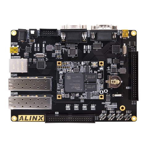
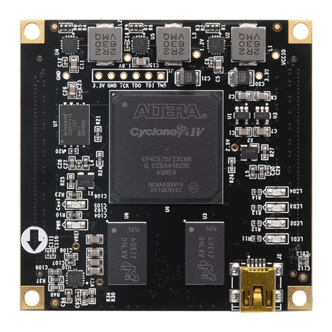
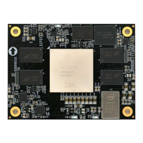
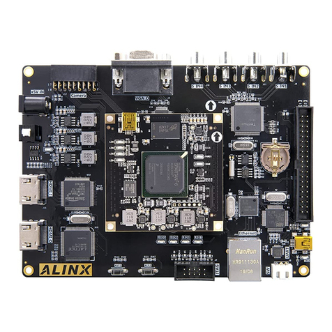
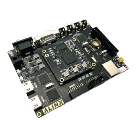
Alinx ZYNQ 7000 User manual

ZYNQ7000 FPGA
Development Board
AX7020
User Manual

ZYNQ FPGA Development Board AX7020 User Manual
2 / 47
Version Record
Revision
Date
Release By
Description
Rev 1.0
2019-04-24
Rachel Zhou
First Release

ZYNQ FPGA Development Board AX7020 User Manual
3 / 47
Table of Contents
Version Record...................................................................................................... 2
Part 1: FPGA Development Board Introduction................................................6
Part 2: Dimensional structure...............................................................................8
Part 3: Power Supply.............................................................................................9
Part 4: ZYNQ Chip...............................................................................................12
Part 4.1: JTAG Interface............................................................................. 14
Part 4.2: FPGA Power System..................................................................15
Part 4.3: ZYNQ boot configuration........................................................... 16
Part 5: Clock Configuration................................................................................ 17
Part 5.1: PS system clock source............................................................. 17
Part 5.2: PL system clock source..............................................................18
Part 6:ZYNQ Processor System (PS) peripherals......................................19
Part 6.1: QSPI Flash................................................................................... 19
Part 6.2: DDR3 DRAM................................................................................21
Part 6.3: Gigabit Ethernet Interface..........................................................24
Part 6.4: USB2.0 Interface......................................................................... 27
Part 6.5: USB to Serial Port....................................................................... 29
Part 6.6: SD Card Slot................................................................................ 30
Part 6.7: PS PMOD connector.................................................................. 31
Part 6.8: User LEDs.................................................................................... 32
Part 6.9: User Buttons.................................................................................33
Part 7:ZYNQ Programmable Logic (PL) peripherals..................................34
Part 7.1: HDMI Interface.............................................................................34
Part 7.2: EEPROM 24LC04....................................................................... 37
Part 7.3: Real Time Clock DS1302...........................................................38
ZYNQ FPGA Development Board AX7020 User Manual
4 / 47
Part 7.4: Expansion Port J10.....................................................................39
Part 7.5: Expansion Port J11..................................................................... 42
Part 7.6: User LEDs.................................................................................... 45
Part 7.7: User Buttons.................................................................................46

ZYNQ FPGA Development Board AX7020 User Manual
5 / 47
The ZYNQ7000 FPGA development platform uses XILINX's Zynq7000
SOC chip XC7Z020 solution, which uses ARM+FPGA SOC technology to
integrate dual-core ARM Cortex-A9 and FPGA programmable logic on a single
chip. The Xilinx Zynq7000 series XC7Z020-2CLG400I is used as the core
processor, which has rich hardware resources and peripheral interfaces on
ARM and FPGA respectively. Adhering to the "exquisite, practical, and concise"
design concept, it is not only suitable for software verification of software
workers, but also for hardware design of hardware developers, that is, system
cooperation of software and hardware, and accelerate the development
process of the project.

ZYNQ FPGA Development Board AX7020 User Manual
6 / 47
Part 1: FPGA Development Board Introduction
The AX7070 FPGA development board uses Xilinx's Zynq7000 series of
chips, model XC7Z020-2CLG400I, in a 400-pin FBGA package. The
ZYNQ7000 chip can be divided into a processor system part (PS) and a
programmable logic part (PL). On the AX7020 development board, the PS and
PL sections of the ZYNQ7000 are equipped with a wealth of external interfaces
and devices for user convenience and functional verification. In addit2ion, the
Xilinx USB Cable downloader circuit is integrated on the AX7020 FPGA
development board, so users can download and debug the AX7020 FPGA
development board with a USB cable.
Figure 1-1 is the Schematic diagram of the entire AX7020 FPGA
development board:
Figure 1-1: The Schematic Diagram of the AX7020
Through this diagram, you can see the interfaces and functions that the
AX7010 FPGA Development Board contains:

ZYNQ FPGA Development Board AX7020 User Manual
7 / 47
+5V power input, maximum 2A current protection
Xilinx ARM+FPGA chip Zynq-7000 XC7Z020-2CLG400I
DDR3
Two large-capacity 4Gbit (A total of 8Gbit) high-speed DDR3 SDRAMs
can be used as a cache for ZYNQ chip data or as a memory for the
operating system
QSPI FLASH
A 256Mbit QSPI FLASH memory chip can be used as a Uboot file for
ZYNQ chips, storage of system files and user data;
Gigabit Ethernet Interface
1-channel 10/100M/1000M Ethernet RJ45 interface for Ethernet data
exchange with computers or other network devices.
HDMI Input/Output Interface
The 1-channel HDMI image video input and output interface, can realize
1080P video image transmission
USB2.0 HOST Interface
1-channel USB HOST interface, to connect with external USB slave
devices, such as connecting a mouse, keyboard, USB flash drive etc.
The USB interface uses a flat USB interface (USB Type A).
USB2.0 OTG Interface
1-channel high-speed USB2.0 OTG interface for OTG communication
with PC or USB devices
USB Uart Interface
1-channel USB Uart interface for serial communication with PC or
external devices
RTC real time clock
One of RTC real time clock with battery holders, battery model CR1220.
EEPROM 24LC04
One piece of IIC interface EEPROM 24LC04

ZYNQ FPGA Development Board AX7020 User Manual
8 / 47
LED Light
6 LEDs; 2 PS control LED, 4 PL control indicators.
Button
7 buttons; 1 reset button, 2 buttons controlled by PS, 4 buttons
controlled by PL.
Clock
An on-board 33.333Mhz active crystal oscillator provides a stable clock
source for the PS system, a 50MHz active crystal oscillator that
provides additional clocking for the PL logic
2-way 40-pin expansion port
2-way 40-pin 0.1inch spacing expansion port for extending the IOs of
ZYNQ PL parts, and can be connect to various ALINX modules
(binocular camera, TFT LCD screen, high-speed AD module, etc.)
1-way 12-pin expansion port
1-way 12-pin 0.1inch spacing expansion port for extending the MIO of
ZYNQ PS system
USB JTAG Interface
One way USB JTAG port, debug and download ZYNQ system through
USB cable and onboard JTAG circuit
Micro SD card holder
1-channel Micro SD card holder, to insert SD card for stores operating
system images and file systems.
Part 2: Dimensional structure
The size of the development board is 130mm x 90mm, and the PCB is
designed with an 8-layer board. There are 4 screw positioning holes around the
board for fixing the development board. The holes diameter of the positioning
hole is 3.5mm, and the dxf structure diagram is provided in the documents.

ZYNQ FPGA Development Board AX7020 User Manual
9 / 47
Figure 2-1: FPGA Size Dimension
Part 3: Power Supply
The power input voltage of the development board is DC5V, The
schematic diagram of the power supply design on the AX7020 FPGA
development board is shown in Figure 3-1

ZYNQ FPGA Development Board AX7020 User Manual
10 / 47
Figure 3-1: Power Supply Schematic
The development board is powered by +5V, and is converted into +3.3V,
+1.5V, +1.8V, +1.0V four-way power supply through four DC/DC power supply
chip TLV62130RGT. Each output current can be up to 3A. VCCIO power is
generated by one LDO SPX3819M5-3-3, and VCCIO is mainly used to power
the BANK35 of ZYNQ. By replacing other LDO chips, the BANK35's IO can be
adapted to different voltage standards. VTT and VREF Voltage required by
DDR3 are generated by 1.5V via TI's TPS51200. The functions of each power
distribution are shown in the following table below:
Power Supply
Function
+1.0V
ZYNQ Core Voltage
+1.5V
DDR3, ZYNQ Bank502
+1.8V
ZYNQ auxiliary voltage, ZYNQ PLL, ZYNQ Bank501, VCCIO, Ethernet,
USB 2.0
+3.3V
ZYNQ VCCIO, Gigabit Ethernet, Serial Port, HDMI, RTC,
FLASH,EEPROM SD Card

ZYNQ FPGA Development Board AX7020 User Manual
11 / 47
VREF, VTT
DDR3
VCCIO
ZYNQ Bank35
Because the power supply of the ZYNQ FPGA has the power-on
sequence requirements, in the circuit design, we have designed according to
the power requirements of the chip. The power-on sequence is
+1.0V->+1.8V->+1.5 V->+3.3V->VCCIO, circuit design to ensure the normal
operation of the chip. Figure 3-2 shows the circuit design of the power supply:
Figure 3-2: Power Supply Circuit
In the PCB design, an 8-layer PCB is used, and a separate power supply
layer and GND layer are reserved, so that the power supply of the entire
development board has very good stability. Test points for each power supply
are reserved on the PCB so that the user can confirm the voltage on the board.
Figure 3-3: Test Points for Power supply on the Board

ZYNQ FPGA Development Board AX7020 User Manual
12 / 47
Part 4: ZYNQ Chip
The AX7020 FPGA development board uses Xilinx's Zynq7000 series chip,
model XC7Z020-2CLG400I. The chip's PS system integrates two ARM
CortexTM-A9 processors, AMBA® interconnects, internal memory, external
memory interfaces and peripherals. These peripherals mainly include USB bus
interface, Ethernet interface, SD/SDIO interface, I2C bus interface, CAN bus
interface, UART interface, GPIO etc. The PS can operate independently and
start up at power up or reset. Figure 2-1 detailed the Overall Block Diagram of
the ZYNQ7000 Chip.
Figure 4-1:
Overall Block Diagram of the ZYNQ7000 Chip
The main parameters of the PS system part are as follows:
ARM dual-core CortexA9-based application processor, ARM-v7
architecture, up to 800MHz
32KB level 1 instruction and data cache per CPU, 512KB level 2 cache
2 CPU shares
On-chip boot ROM and 256KB on-chip RAM

ZYNQ FPGA Development Board AX7020 User Manual
13 / 47
External storage interface, support 16/32 bit DDR2, DDR3 interface
Two Gigabit NIC support: divergent-aggregate DMA, GMII, RGMII,
SGMII interface
Two USB2.0 OTG interfaces, each supporting up to 12 nodes
Two CAN2.0B bus interfaces
Two SD card, SDIO, MMC compatible controllers
2 SPIs, 2 UARTs, 2 I2C interfaces
4 sets of 32bit GPIO, 54 (32+22) as PS system IO, 64 connected to PL
High bandwidth connection within PS and PS to PL
The main parameters of the PL logic part are as follows:
Logic Cells: 28K
Look-up-tables (LUTs): 17600
Flip-flops: 35200
18x25MACCs:80
Block RAM:
240KB
Two AD converters for on-chip voltage, temperature sensing and up
to 17 external differential input channels, 1MBPS
XC7Z020-2CLG400I chip speed grade is -2,Industrial grade, package is
BGA, pin pitch is 0.8mm the specific chip model definition of ZYNQ7000 series
is shown in Figure 4-2

ZYNQ FPGA Development Board AX7020 User Manual
14 / 47
Figure 4-2: The Specific Chip Model Definition of ZYNQ7000 Series
The chip of the BGA package, the pin name is in the form of letters +
numbers, such as E3, G3 and so on. In the schematic, you see that the pin
name is alpha + digit, which means it is a BGA package pin. Figure 4-3 detailed
the XC7Z010 chip on the Board.
Figure 4-3: The XC7Z020 chip on the Board
Part 4.1: JTAG Interface
AX7020 FPGA development board, integrated JTAG download debugging
circuit, users do not need to purchase additional Xilinx downloader. Only a USB
cable can be used for ZYNQ development and debugging. On the AX7010
development board, a FTDI USB bridge chip FT232HL is used to realize USB
and ZYNQ JTAG debug signals TCK, TDO, TMS, TDI for data communication.

ZYNQ FPGA Development Board AX7020 User Manual
15 / 47
Figure 4-4 is the JTAG port schematic diagram.
Figure 4-4: The JTAG port schematic
On the AX7020 FPGA development board, the JTAG interface is USB
interface. Users can connect the PC and JTAG interface to the ZYNQ system
debugging through the USB cable provided by us.
Figure 4-5: The JTAG port on the FPGA Board
Part 4.2: FPGA Power System
The power supply of the ZYNQ chip is divided into the PS system part and

ZYNQ FPGA Development Board AX7020 User Manual
16 / 47
the PL logic part, and the two parts of the power supply work independently.
The power supply of the PS system part and the power supply of the PL logic
part have a power-on sequence. The abnormal power-on sequence may cause
the ARM system and the FPGA system to not work properly.
The power supply for the PS section is VCCPINT, VCCPAUX, VCCPLL,
and PS VCCO. VCCPINT is the PS core power supply pin, connected to 1.0V;
VCCPAUX is the PS system auxiliary power supply pin, connected to 1.8V;
VCCPLL is the PS internal clock PLL power supply pin, also connected to 1.8V;
PS VCCO is BANK voltage, Including VCCO_MIO0, VCCO_MIO1 and
VCCO_DDR, depending on the connected peripherals, the connected power
supply will be different. On the AX7010 development board, VCC_MIO0 is
connected to 3.3V, VCCO_MIO1 is connected to 1.8V, and VCCO_DDR is
connected to 1.5V. The PS system requires that the power-up sequence be
VCCPINT first, then VCCPAUX and VCCPLL, and finally PS VCCO. The order
of power outages is reversed.
The power supply for the PL section is VCCINT, VCCBRAM, VCCAUX and
VCCO. VCCPINT is the FPGA core power supply pin, connected to 1.0V;
VCCBRAM is the power supply pin of the FPGA block RAM; connected to 1.0V;
VCCAUX is the FPGA auxiliary power supply pin, connected to 1.8V; VCCO is
the voltage of each BANK of PL, including BANK13, BANK34, BANK35, on the
AX7010 development board, the voltage of BANK is connected to 3.3V. The PL
system requires that the power-up sequence be VCCINT first, then VCCBRAM,
then VCCAUX, and finally VCCO. If VCCINT and VCCBRAM have the same
voltage, they can be powered up at the same time. The order of power outages
is reversed.
Part 4.3: ZYNQ boot configuration
The AX7020 development platform supports three boot modes. The three
boot modes are JTAG debug mode, QSPI FLASH and SD card boot mode.

ZYNQ FPGA Development Board AX7020 User Manual
17 / 47
After the ZYNQ702 chip is powered up, it will detect the level of the responding
MIO port to determine which startup mode. Users can select different startup
modes through the J13 jumper on the FPGA development board. The J13
startup mode configuration is shown in Table 4-1.
J13
Jump cap position
Start mode
Connect the left two pins
SD Card
Connect the middle two pins
QSPI FLASH
Two pins connected to the right
JTAG
Table 4-1: startup mode configuration
Part 5: Clock Configuration
The AX7020 FPGA development board provides active clocks for the PS
system and the PL logic, respectively. The PS system and PL logic can work
independently.
Part 5.1: PS system clock source
The ZYNQ chip provides a 33.333MHz clock input to the PS section via
the X1 crystal on the development board. The input of the clock is connected to
the pin of the PS_CLK_500 of the BANK500 of the ZYNQ chip. The schematic
diagram is shown in Figure 5-1:
Figure 5-1: Active crystal oscillator to the PS section

ZYNQ FPGA Development Board AX7020 User Manual
18 / 47
Figure 5-2: 33.333Mhz active Crystal Oscillator on the FPGA board
PS Clock Pin Assignment
Signal Name
ZYNQ Pin
PS_CLK
E7
Part 5.2: PL system clock source
The AX7020 FPGA development board provides a single-ended 50MHz
PL system clock source with 3.3V supply. The crystal output is connected to
the FPGA global clock (MRCC), which can be used to drive user logic circuit
within the FPGA. The schematic diagram of the clock source is shown in Figure
5-3.
Figure 5-3: PL system clock source

ZYNQ FPGA Development Board AX7020 User Manual
19 / 47
Figure 5-4: 50Mhz active crystal oscillator on the FPGA board
PL Clock pin assignment:
Signal Name
ZYNQ Pin
PL_GCLK
U18
Part 6:ZYNQ Processor System (PS) peripherals
ZYNQ is composed of the PS part of the ARM system and the PL part of
the FPGA logic. Some peripherals on the development board are connected to
the IO of the PS, and some peripherals are connected to the IO of the PL. First
introduce the peripherals connected to the PS part.
Part 6.1: QSPI Flash
The AX7020 FPGA development board is equipped with a 256MBit
Quad-SPI FLASH chip, model W25Q256, which uses the 3.3V CMOS voltage
standard. Due to the non-volatile nature of QSPI FLASH, it can be used as a
boot device for the system to store the boot image of the system. These
images mainly include FPGA bit files, ARM application code, and other user
data files. The specific models and related parameters of QSPI FLASH are
shown in Table 6-1.
Position
Model
Capacity
Factory
U6
W25Q256BV
32M Byte
Winbond
Table 6-1: QSPI FLASH Specification

ZYNQ FPGA Development Board AX7020 User Manual
20 / 47
QSPI FLASH is connected to the GPIO port of the BANK500 in the PS
section of the ZYNQ chip. In the system design, the GPIO port functions of
these PS ports need to be configured as the QSPI FLASH interface. Figure 6-1
shows the QSPI Flash in the schematic.
Figure 6-1: QSPI Flash Connection Diagram
Configure chip pin assignments:
Signal Name
ZYNQ Pin Name
ZYNQ Pin Number
QSPI_SCK
PS_MIO6_500
A5
QSPI_CS
PS_MIO1_500
A7
QSPI_D0
PS_MIO2_500
B8
QSPI_D1
PS_MIO3_500
D6
QSPI_D2
PS_MIO4_500
B7
QSPI_D3
PS_MIO5_500
A6
This manual suits for next models
1
Table of contents
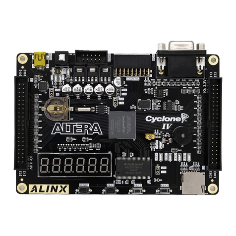
Other Alinx Computer Hardware manuals

Alinx
Alinx AV6045 User manual

Alinx
Alinx ALTERA AC4040 User manual

Alinx
Alinx AXU15EGB User manual

Alinx
Alinx KINTEX UltraScale AXKU062 User manual

Alinx
Alinx ZYNQ AC7Z035 User manual

Alinx
Alinx ALTER AC4075 User manual

Alinx
Alinx AV6150 User manual

Alinx
Alinx ACU2CG User manual

Alinx
Alinx AN9134 User manual

Alinx
Alinx UltraScale+ AXU4EV-P User manual