manuals.online logo
Brands
  1. Home
  2. •
  3. Brands
  4. •
  5. Allegion
  6. •
  7. Door Opening System
  8. •
  9. Allegion LCN 8310-836T User manual

Allegion LCN 8310-836T User manual

75.5739.04 ALLEGION 8310-836 20201103 Page 1 of 4
8310-836T / 8310-836TW
BATTERY REPLACEMENT: 433 MHz - CR2032 3 volt
1
2
3
DESCRIPTION
1. Top end cap
2. Plate assembly
3. Bottom end cap
75.5739.04 ALLEGION 8310-836 20201103 Page 1 of 4
Low-prole push plates
8310-836T (hard-wired)
8310-836TW (wireless)
ENGLISH
Page 2 of 4 75.5739.04 ALLEGION 8310-836 20201103
NOTES:
1. The junction box and the installation of the junction box must be in accordance with National Electric Code (NEC) or local
codes.
2. Hole sizes to be determined by size of materials being used.
Only trained and qualified
personnel are recommended
to install and set up the
sensor.
The warranty is invalid if
unauthorized repairs are
made or attempted by
unauthorized personnel.
Always test the proper
operation of the installation
before leaving the premises.
The door control system
and the header cover
profile must be correctly
grounded.
The 8310-836 (hard-wired or wireless) may be mounted to a wall or a bollard.
• When hard-wiring to a wall, a junction box1must first be mounted flush with the wall, and no
less than 34 3⁄8” from the finished floor (or top of baseboard or cove molding, if present) to the
center of the electrical box.
• When hard-wiring to a bollard without a hole, measure 34 3⁄8” from the bottom of the bollard
and drill a wire passage hole2in the center. Now measure 37 5⁄8” from the bottom of the
bollard and drill a hole2in the center for the top mounting screw. Attach the LPR to the bollard
using the top screw. Drill a hole at the bottom (1 ¾” from the bottom of the bollard) for the
LPR mounting hole location and secure with second screw.
Shut off all power going to header before attempting any wiring procedures.
Maintain a clean and safe environment when working in public areas.
Constantly be aware of pedestrian traffic around the door area.
Always stop pedestrian traffic through the doorway when performing tests that may result in unexpected
reactions by the door.
ESD (electrostatic discharge): Circuit boards are vulnerable to damage by electrostatic discharge. Before
handling any board, ensure you dissipate your body’s ESD charge.
Always check placement of all wiring before powering up to ensure that moving door parts will not catch
any wires and cause damage to equipment.
Ensure compliance with all applicable safety standards (i.e. ANSI A156.10) upon completion of installation.
DO NOT attempt any internal repair of the components. Unauthorized disassembly or repair:
1. May jeopardize personal safety and may expose one to the risk of electrical shock.
2. May adversely affect the safe and reliable performance of the product resulting in a voided warranty.
Prior to mounting the plate, ensure the two (2) in-transit locking screws are removed
from the back of the plate. These screws are not required for installation.
Mounting the plate on an uneven surface will cause the switching mechanism to hold
the circuit closed at all times.
!
CAUTION
PRECAUTIONS
MOUNTING INFORMATION
Page 2 of 4 75.5739.04 ALLEGION 8310-836 20201103
READ BEFORE BEGINNING INSTALLATION/PROGRAMMING/SET-UP
75.5739.04 ALLEGION 8310-836 20201103 Page 3 of 475.5739.04 ALLEGION 8310-836 20201103 Page 3 of 4
MOUNTING
Do not remove the face plate during mounting.
1 2 3
5 6
7 8
4
NOTES:
1. If installing a wireless version, allow the top end cap assembly to hang loosely by the cable during set-up. Do not unwire.
2. Image shown has the plate and end cap removed for illustration purposes.
3. To avoid activation issues, do not push excess wire(s) into the plate assembly during reassembly.
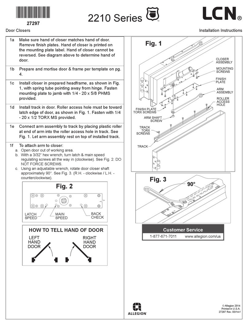
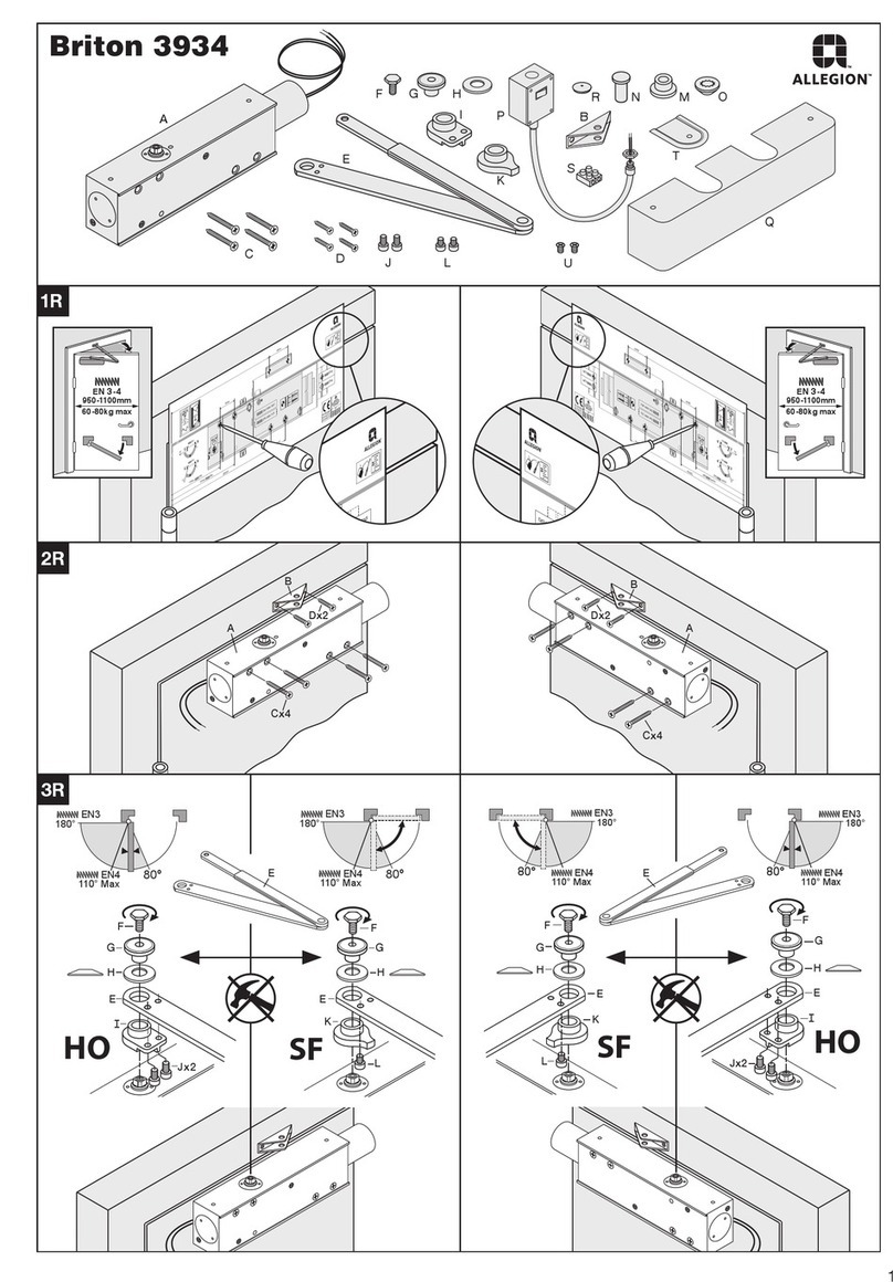
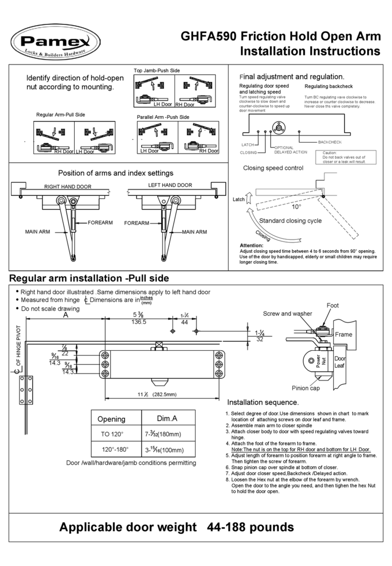
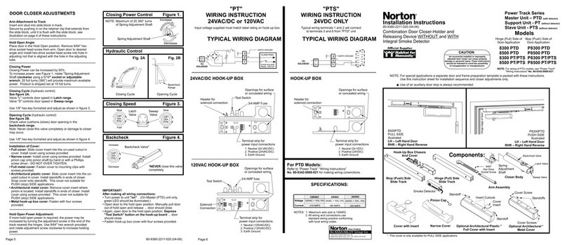
Remove the top end cap by
removing its screw covers and
then removing the screws.
After removing the top end
cap, remove the top and
bottom locking hole screws.1
To complete a wireless set-up
(or change the battery), refer
to User’s Guide 75.5315.
To mount to a bollard, attach
the switch to the bollard using
a 10-24 × 0.75 mounting screw
and nylon spacer.
To secure the bottom plate
assembly, first slide the front
plate upwards, and then insert
a top end cap screw into the
threshold to hold.
Secure the plate assembly using
the bottom mounting screw.
Remove the top end screw from
base and slide down.
Replace the top end cap with
provided screws and reinstall
the screw covers.
Make necessary wiring
connections.2Ensure excess
wiring is kept inside the
junction box, if used.3
Install an appropriate anchor
through the top mounting
hole.
Page 4 of 4 75.5739.04 ALLEGION 8310-836 20201103
Do not leave problems unresolved. If a satisfactory solution cannot be achieved after troubleshooting
a problem, please contact Allegion at 1-877-671-7011. If you must wait for the following workday to
call Allegion, leave the door inoperable until satisfactory repairs can be made. Never sacrifice the safe
operation of the automatic door or gate for an incomplete solution.
For more information, visit www.allegion.com.
TECHNICAL SPECIFICATIONS
CLEANING
To clean the plates, use only a damp, non-abrasive cloth. Regular cleaning with harsh solvents or
abrasive materials may cause deterioration of the paint coating. Ensure the user is aware of this
procedure.
Original Instructions | PLEASE KEEP FOR FURTHER USE - DESIGNED FOR COLOR PRINTING
Specifications are subject to change without prior notice.
All values measured in specific conditions.
SWITCH SUB-ASSEMBLY
Contact configuration: SPST N.O.
Switching voltage: 0.1 – 50 VDC
Switching capacity: 1 W
Switching current: 0.005 – 100 ma DC
Operating temperature: -32 – 212 °F (-35 – 100 °C)
PUSH PLATE ASSEMBLY
Base material: 6063 aluminum
Face plate material: 304 stainless steel
Switch actuator material: nylon 66
End cap material: UL94 ABS
Hardware material: stainless steel
Page 4 of 4 75.5739.04 ALLEGION 8310-836 20201103
The sensor manufacturer cannot be held responsible for incorrect installations or inappropriate adjustments of the sensor/device; therefore, the sensor
manufacturer does not guarantee any use of the sensor outside of its intended purpose.
The sensor manufacturer strongly recommends that installation and service technicians be AAADM-certified for pedestrian doors, IDA-certified for
doors/gates, and factory-trained for the type of door/gate system.
Installers and service personnel are responsible for executing a risk assessment following each installation/service performed, ensuring that the sensor
system installation is compliant with local, national, and international regulations, codes, and standards.
Once installation or service work is complete, a safety inspection of the door/gate shall be performed per the door/gate manufacturer recommendations
and/or per AAADM/ANSI/DASMA guidelines (where applicable) for best industry practices. Safety inspections must be performed during each service
call – examples of these safety inspections can be found on an AAADM safety information label (e.g. ANSI/DASMA 102, ANSI/DASMA 107).
Verify that all appropriate industry signage and warning labels are in place.
INSTALLATION/SERVICE COMPLIANCE EXPECTATIONS

This manual suits for next models

1

Other Allegion Door Opening System manuals

Allegion LCN Benchmark AU9100 Series User manual

Allegion

Allegion LCN Benchmark AU9100 Series User manual

Allegion LCN 2210 Series User manual

Allegion

Allegion LCN 2210 Series User manual

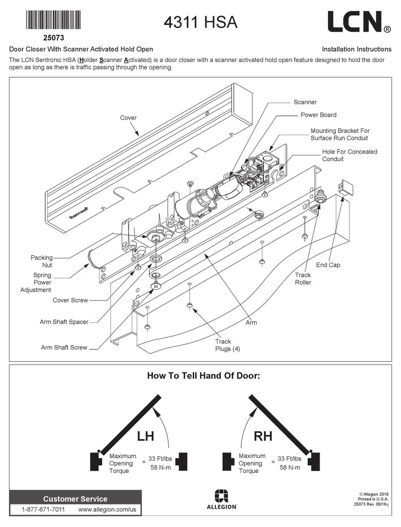
Allegion LCN 4311 HSA User manual

Allegion

Allegion LCN 4311 HSA User manual

Allegion VON DUPRIN XP98 Series User manual

Allegion

Allegion VON DUPRIN XP98 Series User manual

Allegion LCN 1461 Series User manual

Allegion

Allegion LCN 1461 Series User manual

Allegion Von Duprin 98 Series User manual

Allegion

Allegion Von Duprin 98 Series User manual

Allegion Briton 2130B User manual

Allegion

Allegion Briton 2130B User manual

Allegion FALCON SC93 Series User manual

Allegion

Allegion FALCON SC93 Series User manual

Allegion Von Duprin QEL9447 User manual

Allegion

Allegion Von Duprin QEL9447 User manual

Allegion Briton 1110C User manual

Allegion

Allegion Briton 1110C User manual

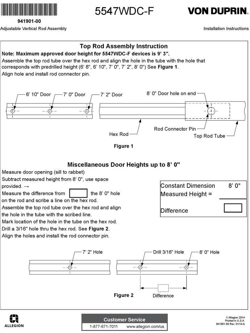
Allegion Von Duprin 5547WDC-F User manual

Allegion

Allegion Von Duprin 5547WDC-F User manual

Allegion LCN 4040SE User manual

Allegion

Allegion LCN 4040SE User manual

Allegion interflex IF-241 User manual

Allegion

Allegion interflex IF-241 User manual

Allegion Briton 3934 Manual

Allegion

Allegion Briton 3934 Manual

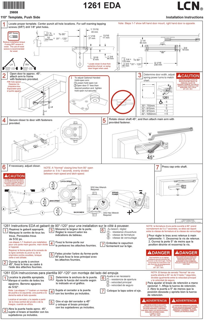
Allegion LCN 1261 EDA User manual

Allegion

Allegion LCN 1261 EDA User manual

Popular Door Opening System manuals by other brands

GEZE TSA 160 NT manual

GEZE

GEZE TSA 160 NT manual

Assa Abloy Corbin Russwin DC8200 Series installation instructions

Assa Abloy

Assa Abloy Corbin Russwin DC8200 Series installation instructions

Bortoluzzi slider M50 manual

Bortoluzzi

Bortoluzzi slider M50 manual

Manaras Opera EYLESSO42 user manual

Manaras Opera

Manaras Opera EYLESSO42 user manual

Hafele 940.41.043 Installation instructions operating instructions

Hafele

Hafele 940.41.043 Installation instructions operating instructions

Entrematic Ditec KS200VA installation manual

Entrematic

Entrematic Ditec KS200VA installation manual

Label Neptis SMP user manual

Label

Label Neptis SMP user manual

Label NEXT 75 user manual

Label

Label NEXT 75 user manual

Entrematic Ditec DAS200HD Technical manual

Entrematic

Entrematic Ditec DAS200HD Technical manual

Entrematic Ditec VALLOK installation manual

Entrematic

Entrematic Ditec VALLOK installation manual

TOPP K200T Instructions for installation and use

TOPP

TOPP K200T Instructions for installation and use

Command access MLRK1 Series Insert Instructions

Command access

Command access MLRK1 Series Insert Instructions

Dorma 8916 JT manual

Dorma

Dorma 8916 JT manual

Swissdoor ETS 73 Mounting and operating instructions

Swissdoor

Swissdoor ETS 73 Mounting and operating instructions

Dorma MUTO COMFORT L 80 Mounting instructions

Dorma

Dorma MUTO COMFORT L 80 Mounting instructions

TownSteel ED3727 installation instructions

TownSteel

TownSteel ED3727 installation instructions

Dorma AGILE 150 Installation instruction, care instructions, service and maintenance

Dorma

Dorma AGILE 150 Installation instruction, care instructions, service and maintenance

Cavity Sliders Solic CS005 Operation manual

Cavity Sliders

Cavity Sliders Solic CS005 Operation manual

manuals.online logo
manuals.online logoBrands
  • About & Mission
  • Contact us
  • Privacy Policy
  • Terms and Conditions

Copyright 2025 Manuals.Online. All Rights Reserved.