manuals.online logo
Brands
  1. Home
  2. •
  3. Brands
  4. •
  5. Amana
  6. •
  7. Air Conditioner
  8. •
  9. Amana ERCF18-UO1B User manual

Amana ERCF18-UO1B User manual

fill
out the homeowner's
reg;ist1!"dtiion
the be sure
to
include
the installation date.
Your warranty certificate is also sUl,plied with the unit. Read
car'efullly and note what is covered. the warranty certificate in a
you can find if necessary.
Read this manual
You
should become th'lrougll1ly
l',,",ilh
...
unit's and the many
it
offers.
If
additional instructions are call the dealer
t1mou~:h
whom
the was
IMPORTANT NOTE TO THE HOMEOWNER
IMPORTANT:
To
LEAVE THIS MANUAL
WITH THE HOMEOWNER.
.•..
...
•Before this unit read this manual to
..
familiarize on the items
\,
which must adhered to, as, clearance
around electrical
spe:cificatiolrlS
refrig,:ralnt
cOfilne,:ti,)Us
and
fQur
hour
"Notice:
It
is the Owner's and Installer's res:ponsiibility
to
locate this so
as
to pf()vi,le
and access
fOf
futufe maintenance
and
"PTVlCP
OWNERS MANUAL
ctio
r
IN
I
ERCF24·UOlll ERCF3ll-U01B EllCFllIHI01B ERCF42·UOll:\ ERCF4S·\J01B ERCF4S·\J03B ERCF6ll-U01B ERCF6ll-U03B
SPECIFICATIONS
MODEL NUMBER
MANUFACTURING NUMBER
NOMINAL COOLING CAPACITY
(BTUH).
1HERMETIC
COMPo
{TYPE AND PHASE}
fL
Amps
LA. Amps
ERCFllHl01B
18.000
TEC ttl
7.8
40.6
24,000
TEC
1,0
10,2
51.0
P67471·13C P61411-14C P61411-15C P67471·16C P67747·18C P67747·11C P67747.19C
30,000 36,000 42,000 48,000 48,000 60.000 60,000
.Cope
1,1l
Cope
1):)
Cope
III
Cope
1,0
Cope
3):)
TEC
1,£l
TEC
$,tl
19.9 27.3
87.0 83.5 93.0 114.0 84.0 132.0 103.0 •
CONDENSER
COil
Tol
00"
Rows
Fins/in.
Face Area Sq.
Ft
CONDENSER
FAN
MOTOR,
PSC
TYPE
LA.
I
fL.
Amps
I
Oil
Ports
:Ys
11'.1
17
8.65
'/10
.90
.70
Sleeve
Yes
%
1Y2
17
8.65
2.20
1.20
Sleeve
Ves
%%%% % % %
lY2 222 2 2 2
16
17
18 16 16 18 18
11.5 11.5 16.47 16.47 16.47 16.47 16.47
1/4
V4
'/3
V,
V,
2.40 3.10 3.02 2.0 2.0
2.1 2.1
1.50 1.50 1.50 4.85 4.85 4.7 4.7
Sleeve Sleeve Sleeve Sleeve Sleeve Sleeve Sleeve
Yes
Yes Yes Yes Yes Yes Yes
REFRIGERANT CONNECTIONS
APPROXIMATE WEIGHTS (lbs.)
Net 167 193 210 230 254 262
Shipping
183 212 225 245 274 282
loierance:
Minus
5%
on
208V,
plus
10%
on
208
230V,
mini 10%
on
230V.
3200 3150 3900 4130 4130
Refer 10
unit
rating plate
for
correct
refrigerant charge.
~ ~
M M M
34344
~/f
7/at
%rI.
~li{,.
24.28 24.28
44
4550 4550
208/230 208/230
34
8(10) 10 (10)
36.2 22.7
50 35
295 287
315 307
255
275
23.0
35
4
10 (10)
208/230
50
35.1
3
8(10)
208/230
29.6
45
208/230
3
10
(10)
26.4
35
3
10 (10)
208/230
30
21.61
3
10 (10)
208/230
2700
14.0
20
4
20
3
14
(14)
208/230
15
10.50
1900
20
3
3
14 (14)
208/230
UNIT
POWER CHARACTERISTICS' (60 cycle)
CONDENSER AIR CFM
MINIMUM CIRCUIT AMPACITY
fACTORY INSTALLED
"HACR"
BRK.
(amps)
POWER SUPPLY"
Number
Wires
Size (AWG) (GRD.)
-Compression
Liquid
-Compression
FAN
BLADE
-CONDENSER
Diameter
Number
aisdes
UNIT
FACTORY CHARGE R22 (oz.)
TOP
VIEW
SECTION AI.
Underwriters' Ilstlld
fer
outdoor Inslell.tion
2
A
HEATER.
UNIT
HAS
BEEN
ENERGIZED
MINI·
MUM
OF
fOlJR (4)KOIJRS.
L
CAUTION -IMPORTANT
WllrrA'ntv in force and to
''',I'Ujl'\,"''
",
THE
,",,,,,,,,,r.T'"
CLEAN OUTSIDE COIL
The coil in the outdoor unit should be cleaned
as necessary to it free
of
dirt and debris.
Know
YOUI'
New Central Air Conditioner
Anew central can be one
of
the finest
to
home
comfort.
This manual tells you
to
operate your unit and suggests some maintenance
you
must
to
insure
top
year
after
year.
THE COOLING COIL
When your air cOlllditionirlg is in the
removes
heat
from
the
inside
co:ndimsing unit causes
r"f:r;",,,r,~nt
to to
your
inside
The evaporates in your coil
and
the:rejfone,
the air
over
it is As
the air is cooled and some
of
its
heat
to
the
to
the coil in
your
cOllde:nsiing
unit.
The
"",erv,;n"
the heat removed from the air
inside condenses in the coil
of
your
COllde'l1sling
unit
this
heat
to
the
outside
air
circulated continues until your home
is cooled to
of
your room thermostat, at
which time the turns off.
central
inside
of
THE OUTSIDE COIL (Condfl,nStlll')
This coil in the condensil1lg unit has
outside
air
flo,wing
th"",,,,nh
the fin function
of
this coil is
to
the ref'rigenmt
f'I~,,,,:
••
~
here's how youI' CONDENSING UNIT
to prOl/lde coolina
TO THE HOME OWNER
TRUE CENTRAL SYSTEM AIR CONDITIONING
\."U1U'L.III'\IU,
DEIHUI~ltIlF'rlNiG
AND AIR FILTERING
Your
UNIT
has
been
on:)Viide
you with
desig:ne:d
to
meet
your
•
•
HIGH·PRESSURE CUT·OUT
CONTROL
This control will stop the com-
under certain conditions.
It
will
to be manually re-set before
opl~ration
will
resume.
To
re-set
control,
Oil
the outdoor section,
push
in
the reset button,
The High Pressure control will
the unit
ifthe
folloVitilll~
clmdlititlllS
exist
are not '-fil'r""-t,,,rl
to locate
Inoperative Outside Fan Molor
Insufficient Air Across Outside
Coil
Outside
Coil
Restricted
With
Debris
Recirculation
of
Hot
season.)
42, 48 60M
Btuh
units
have
an
internal
crankcase
heater.)
However,
the
heater
must
still
encflil:ized for 4
hours
to
the unit
after
a
pn)lojngt~d
"off"
time.
after
unit's
elc,ctlric;al
dis,conn'ect switch was vacation
or
nc,uu'g
energy
con-
""""',,<r~'Q~"'"
dischmrge line
the
heater
will
be
compressor
eqiuip,ped
with an additional control
CONDENSER
FAN
MOTOIFl.
CRANKCASE HEATER
This unit
•
in
the
unit.
Control
cooling
and
windows
closed
when
unit.
You will live in a
controlled
"climate"
...
in
temperatures
for
your
own
comfort.
4.
filter
is
clean
in
the
furnace
or
the
unit
blower/coil.
Docs
outdoor
fan op,erate'!
5.
Check
to
see
if
the
furnace
or
blower/coil
blower
opi:raltes.
Check
furance
belL
6.
the
unit
condenser
and
the
coil
to
see
if
are
clean.
pressure
control
m
COMPRESSOR
The
compressor
is
pelcm;mf~ntlly
lubricated
and
n>;",i,·p~
BEFORE
YOU
CALL YOUR SERVICEMAN
some
iceman:
I.
Wait afew
minutes
OS
to
30
mlnules)
to
see
if
it
resume
2.
Check
thermostat
to
see
if
it
is nnlne:rlv
3.
Check
fuses
or
breakers
on
elf~ctrIcal
home
power
box
and
reset
the
"~~,,,I,,,
..
(See
circulation
of
air
to
and
from
the
unit
is
absolut!elv
There
are
several
conditions
which
can
shut
off
your
cOJndtmsmg
unit
or
cause
...
here
are
you
should
check
you
call
the
serv·
leaves
and
area
of
the
outdoor
CLEAN
FilTER
Remote
type
systems.
The
filter
used
will
be
the
one
furnace
or
in
the
blower
unit
which
may
have
installed
air
distribution
your
home.
These
should
be
cleaned
and
im,pectf~d
at
least
once
month.
you
have
permanent
filter it
should
be
washed
warm
water,
dried
with
an
adhesive
5!('f'nrrlir,o
to
recommendations.
which
this
on
your
and
usage
of
the
SOME THINGS
electric
or
other
heat
sources
from
thermostat.
S:"nPI·f',·j,.,1
heat
the
thl~mlO!;tat
false
Do
not
cover
up
thermostat.
Allow
over
it
Do
allow
block
the
air
inlet
Oil
FAN
MOTORS
The
on
the
motor
should
be oiled
at
the
of
each
season.
The
of
the
oil
on
page 5will
show
where
Use
No.
20
motor
oiL
NOT
USE
DETERGENT
TYPE
OIL
Caution:
Pull
the
unit
electrical
switch
before
to
oil
the
The
motor
has built in
pnntection
current
or
over
These
de'vic!~s
many
FAil SWiTCH
ROOM
T£MPERATlJRE
THERMOMETER
",'I
A
",'III
thermostats
are
sensitive
and
you
with
.you
can
have
filter
the
air
without
it
to
operate
the
stc,pping
and
or
compressor
and
slll'mitarlecmsly a,cc(lrding
to
the
pre-set
the
the
fan
should
be
set
on
AUTO
...
if
you
continuous
air
flow
it
to
ON.
for
normal
the
bonnetllimit
control
will
the
furnace
How-
ever
the
switch
must
be
set
on
HEAT.
. .
cannot
come
on
at
the
same
time.
4
If
the
above
po'ssil)ility
that
the
on
the
overload
Cooling sl/stem remains
off
reo
of
room temperature.
(blower)
operation
con·
stant.
Cooling system remains
off
rlI'
gardless
of
room tlilmperature.
Fan (blower)
dOllS
not
operate.
Cooling Syst!lm and
fan!blow·
er) cycle
to
mllinmin
selected
room temperature.
Cooling system cycles
to
main·
tain
selected room tel'llperatllrll.
Fan
(blower)
con·
stant.
.;:tfC,,'t'inO
of
the
coml",rp','wlr.
not
there
is
will
open
or
the
compressor
will
protectors.
TYPE A
..•...
SWITCH
OPERATION..
.,
TYPE B
OPERATION
PRE·
tp"H'P,·~,t""p
control
dial
or
and
im·
There
must
be
an
minutes
between
the
"off-time'
•
•
DESCRIPTION
There
is
no
transformer
in
this
comlensil1lg
enel'l~ize
the
24V
control
circuit
for
c01olllllg.
former
in
the
furnace
or
coil/blower
must
be
to
handle
the
draw, a40 v.a.
tra:nsfor'ml~r
Refer
to
in cOll1d,msing
coil/blower
or
correct
electrical
connections.
air
cooled
conden:sing
f'AlTIr"'p~~,,,"
The
unit
and
located
terminals.
thl~rnilO:,tats
are
for
temperature
control
the
conditioned
space,
All
compreSSQrs
sprung
and
mounted
on
rubber
i~AbIAI"<
bill
and
request
for
ins:pection
made
at
once.
Units
are
ShlipIJ1ed
and
it is
the
COiOSI:gm:e
INSTALLATION
RECEIVING
•
•
ioto
an
enclosed
room
or
refrigl~rant
to
outside air.
Never
refrigl~rajnt
vapor
to
an
open
flame because this
which is very
it
becomes
to
warm
a
"pj'r;o,pr"nr
n",rh<,lIv
immerse
the
OPEN
TO
THE
REFRIGERANT
CON-
3.
2.
4.
GENERAL -IMPORTANT
Before
the
installation
to
install
this
cOlilde:nsmg unit he
must
be
the
unit.
The
suction
and line
connections
on
the
unit
are
and
the
unit
has
external
shut
off
valves.
The
also
14"
male
flare connoeetlolls,
valve
core,
to
take
pressure
re<ldlng:5.
See
mustra-
2.
unit
is
pn~·chargf:d
and
is
to
be
emlplo'yed with field
insltal!l~d
and
cornpfmil)ll
unit
and
for
outdoor
instalilation,
and
no
should
added.
The
follml\linlll
should
considered
before
location:
I
These
are
air
cooled
therefore
shOUld
location
the
air
can
be
the
condensor
coil. the
east
or
north
side
of
ais
more
desirable
because
the unit will
not
be
to
the
To
the
it
should
not
from
any
wall
to
the
inlet
Allow minimum
of
12"
between
the
building
and
the
unit
side
which
the
electrical
and
connections
are
made.
install
concrete
base
for
the
cOIlde:nsllOg
unit
set
The
base
should
not
touch
the
of
the
house.
Such
conditions
cause
unit vil:lnlltioll,
if be
transferred
into
If
installed
on
a
be
sure
construction
is
able
to
support
the
Unit
should
6"
wood
or
(H
or
must
also
be
used.
location
near
wh,en~bv
the
shortest
run
minimum
of
turns
are reqiuired.
PT2
PT2
PT3
30100 ,
30100
30100
and
COllJUIoctlon
with
"olnf".rtn
with
all
T&B
T
8<
8Wire Nut
Connector
Type and size
IV'
T&B
T
&.
BWire Nut
T&BWire Nut I
1&8
#10
#8
#12
/I
2
11
4
/I
6
or
more)
of
recommended size
the unit
compressor
contactor
termililals.
AWG
Aluminum
Wlr.
Size
in relation
to
co'nn<~ctiing
the electrical wir-
installation
of
breaker
or
soft
#12
#14
#8
/I
6
'"
4
Rel'riglerall1t
drums
2.
CODES AND ORDINANCES
1.
Select the
eCI1Jiviale:nt
aluminum wire size from the tabu-
lation below:
COlohng
systems,
or
heating
system,
must
be
u,,,,,
..
,,-,,
eXisting local
codes
or
local
codes.
The units must also be installed in
accordance
with
lations
of
the
National Board
of
Fire Underwriters.
thorities should
be
consulted
before in-
stallation
is
The
indoor
air
duct
distribution
must
also
be
installed in
accordance
with
standards
National Board
of
Fire
Underwriters
for the Imitallatilon
Air Warm Air
and
tems Palrnphlf:tS.
ALUMINUM FIELD
WlIfUNIG
Install the electrical conduit
to
the
cOlld~msing
aplPropri.ate openJing
and
size wires in
accordance
to
the
Na-
and/or
the local codes.
When
aluminum
conductors
as !oIlo'i!/s:
the the
above
listed wire nuts
or
bolt
connectors.
entire
connection
with inhibitor and wrap
electrical tape.
INHIBITORS:
.Alcoa
No.
T B - KOPR-Shield.
PRECAUTIONS
IN
HANDLING REFRIGERANTS
be adhered
to
when
the
This
110,rizl)ntal suction Hnes,
as
to
operate
the
unit
before
the
is cOlmpleted.
c,
b.
d,
such
as:
All
horizontal
towards
the
com~lreSS(lr
aids
the
return
REIFRI1GiE'~ATION
PIPING
The
system
is
very
in
I'",,,,,(',,tv
proper
oil
return
to
compres~
COlmpressor and
the
be familiar with all and
sizes
to
be installed
on
a
Certam
prec:au!mnar'y
measures
should
be
adhered
I.
Count
the
number
of
90°
and
45°
elbows and measure
the
of
Find
the
of
in table
number
l.
To
This unit must be grcmndeld.
4.
This
unit
does
no!
have
a
transformer.
.E.C.
class
2, 24VAC 40VA
transformer
must
be used
to
the
control
circuit
of
the
or
system.
SUCTION AND LIQUID LINE SPECIFICATIONS
lines used
to
connect
the
indoor
unit
cOlrld,,:nsing
unit
MUST
BE
clean
and
vertical
SUCTION LINE SIZING
The cmTespmldirlg pres:sufiel
suction
line
at
compressor
may
be
pv"n"n""I"',n
temperature
in
temperatur(; differential is
caused
suctioll line, it
becomes
Ile,~ess(u'y
the
suction line from
the
table on
The
line
shown
,<viii
allow
for
sufficient interm.l line
vpl,,,';lv
(a~lproxj!m,ltejly
1500
to
return
the
oil
to
the
the
necessary
to
"",,,,,\1.,,,'\1
The
(con-
adjusl:able
on
the
be used when
~prvi('ino
interlock
between
the
indoor
section
motor
the
electric
when
CONCRETE BASE DIMENSIONS
PREPARING BASE
When
unit
is
installed on
the
a
level
concrete
base
is
recom-
spt:cif'k
area
and
thickness. Base sizes for the
correspion,dil1lj;!
units
are
shown
in
the
above
sketch.
common
mixture
for
concrete
one
part
Portland
cement,
two
parts
sand
coarse
crushed
rock.
adequa,te
draina~!e
around
the
unit so
that
above
the
concrete
THERMOSTATS
the
thermiost:at
Thermostat
should be located
about
5
ft.
above floor on a
vibration free inside wall in
an
area
with
air
circulation;
must
not be in
an
area
air
GENERAL NOTES -CAUTION
before
op,~ralting
•
•
•
of
in the
cOllde~nsiing
30
of
and
line
coil.
If
the lines have
to
be
than 30 feet, the
has
to
be
im;re:ase~d
decreased to
compensate.
See
chart
on
page
10.
Exercise care in
pn~-fl)rlJl1il1lg
line
to
the unit
and
evaporator
to
avoid
The shut-offvalves/and manifold assemblies
include a
port
valve
core)
sCI'/?'ured
bonnet
over
the
stem
and
aphlgg:ed
components which are
to
connect the
rpj',.io,p,."nf
Please refer
to
the illustrations.
8
2.3
1.6
1.0
.7
1.5
cO()!irlg
coil located
above
the
pn~c2LUtioris
must be
taken
into
nn~v,>nl
at
the
inlet
of
the
rpf'rio'pnn'f
must
enter
state,
TABLE 1
EOIUIV,AU=:Nl
STRAIGHT
PIPE
VERSUS SUCTION
liNE
ELBOWS
e.
line riser must
of
the
per
of
rise,
N"rrr,,,lilv
rp,lnl',i",n
is
not
noticeable
with
a30
the
vapor-pressure
the
EXllm!)le:
One
short
radius copper sweat ell is equal
to
the of two foot
of
0.0.
straight
The
LIQUID LINE SIZING
In sitllati,ons
PRESSURE
DROP
LINES
FOR
REFRIGERANT
22
per
the
evaporator
9. it
must
be round
without
or
on
which
is
to
be
enl2;all:ed
into the unit
to. the threads
of
the unit
and outside
of
the ferrule. Install the
into
the unit
sequence
shown
below.
Til~hten
II.
Insert
into
nut
and ferrule until it
bottoms.
12.
nut
hand
13.
Mark the nut
as
shown below and
the nut an additional turns. Be sure
bottomed
out
If
ch:an~!ed
or
a
bad
connection
the
must
be
cut
off
and
anew
ferrule
must
Prl,,,,,·,,,rI to
redo
connections
as
described
in
thnf'lll~,h
13.
other
the
same
17.
16.
HEX
closed
correct
WHEN
HAVE
Deburr
follmvifill.
instructions
or
TYPICAL VALVE ADAPTER
ue:pness valve
core
to
relieve any gas
pn~SS!llre
which
be
in
the manifold.
RemClve
COlLlpling
nuts
SQ. DRIVE L........----t======::::J
TAKE
REMOVING
PLUG.
BUILT
UP.
6.
Remove
VALVE MANIFOLD ASSEMBLY
For
•
REFRIGERANT CORRECTION CHART
hex wrenches
The shut valves
do
not
VALVE UNTIL IT
TOUCHES
THE
RETAINER.
APPLY
PRESSURE
TO
RETAINER.
thermostat
to
COOLING,
fan AUTO
telllpenlllU:re
control to below room temperature.
",j,'rt"ir"l
switch.
more
than
30
fl.
of
,.",j'r;c,pr"nt
relative
to
OD size and ad,ditilonai
CORRECTION CHART
•ELECTRICAL CONNECTIONS AND
OVERCURRENT DEVICE SIZING
"IiACFl"
BREAKER
TERMINALS
•
"""""
._~_,m··
,_"
__
",. ,
,_._.,,,,_
_
I...VVLlII'iIUl
PERfORMANCE DATA
86
91 303 1lUI lUi 92 307 20.3
911
299 15.8 14.5
111
'304
nUl
114
21l1l
15.4
111.1
81
300
111.2
19
295 14J.I 23.5 76
2116
18.6
115
2113
15,8 10.1 go
2811
19.3
llll
283 15.4 14.1
85
284
llUI
62 279 14.9 19.3
110
2110
111.5
71
215 14.4
23.1:1
15
2l1O
18.2
-----
-"
93 264 15.2 10.3 go 269 18,6
l'l7
284 14.9 15.0 85
261l
16.3
82
2lIO
14.3
11l.l1
go 265 17.9
71 251 13.9 24.1 15 261 11.4
113
10.5 86 254 18.3
86 246 14.1 15.2 83 250 11.7
711
246 17.3
15
240
13.5
13
243
111Jl
91
233 13.9
11l.ll
87 231 17.3
84 229 13.4 15.5
81
233
11.0
19
226 13.2 2ll.2
16
230
1IU
14
223 12.9 24.8 72 226 15.2
69
213 13,5
11.11
85 216 16.1
84
213 13.3 15.8 go 213
11i.4
19
210 12.9 20.5 75 213
111.1
14
201 12.6 25.1 72 210
16.l.l
81
11111
12.1 11.3
83
201 16.3
82
195
12.4
1Ul
llO
191
16.0
17
1112
12.4
211.8
15
195
15.8
72
1112
12.3 25.4
10
192 15.4
86
1110
12.1 11.5 79.5
lllO
15.6
61
175
1Ul
1ll.1
78
1ao
15.6
76 115 12.0 21.0
14
180 15.2
10
110
11.6
25.1 69 115 14.7
12.9
17.1
22.5
21.1
12.1
17.4
22.2
21U
26.4
12.1
1lUI
21.5
26.1
11.9
25.6
11.8
16.3
20.9
25.4
15,1
20.3
24.l1
11.4
1iUl
20.11
25.1
241
11
246
92 231 11.3
87 233 11.0
92 230
111.6
77 226
11:1.3
217 10.8
115
218
11),6
214 10.4
16 211 10.2
-
90 202 10.5
85
199 10.3
90 198
lUI
74 193 9.6
88
1l1O
lUI
83
1110
9.2
19
110 9.4
73
170
9.1
15
202
93 193
12,1)
85
190
llU
111
lIO
1l1O
1.5 21.5
11
1111
1.3 26,1
92 115 1,5 12.2
12
14.6
84
110 1.3
11.11
61
111
170 7.3 21.8
23.9
10
211.4
911
301 10,0
291
291
!l.5
293
9,1
--
----
ll.9
"--
111,1
62
I
22.11
•
bUlb
lIO"l"
.•
00
lnclles
edemal
Iltst!!:: pressure on coil
01
outdoor
section. As Indoor
dry
bUlb temperature Increllsell,
lIsllgllt
Increalle wll! occur In
differential between
In.t
1I1ld
outlet.
low
lind
high
sldll
presllures
lind
power
will
not
challge.
operllllllg
$!'lollid be
plus
Of
minus degrees
tile
typical bulb)
vaille
shown.
operating
unit
be
or
minus :I PSIG
01
the
typical $I!own.
7PSIO
of
the
typical value shown.
limps. (16M
IIlld
24M BTUH unlts),:3
ampll
•
•
•
•
TYPICAL COOLING PERFORMANCE DATA
ERCF42-UQ1B &ECFC42AOM·8 ERCF48·U018,38
ECFC411AOM·B
ERCFllO·U018·3B &ECFCllOAOM·B
Indoof
@141l5CFM
Indoo,
@11100CFM
Indoo,
@2000CFM
AI,
AI,
Tempe,atu,e AMPS.Tempe,atu,e AMPS.
at
'at
Betwe""
T~~"I
T:a'
DlIle,en"e
T':'
Inlet
(WI~~~Il>1
an;lld~~:l
Between
Coillnlel
(Dry
s"dO"!!"1
Press",e
P."ss",e
Unll Pressure P,esaure Unil and
Oullel
Pressu'e !Pre;;su,e Unll
"A"
I
"8"
"C"
"0"
"10"
"8"
"C"
"0"
"10"
"8"
"e"
"0"
"E"
'I"
'I'
"I" PSIG PBIG AMPS.
'I"
PBIG PSiG
HI
311
"I" PlllG PBIG
111
'.
115 67 19.6 84
334
22.5 19.1 8Q.5 336.0 25.0 15.8 18.7 86.5 325.5 32.1 19.9
Ii77 10.7
96
321 23.2 9.7 89.0 324.0 25.5 15.9 9.2 97.5 317.5 33.5
~g:~
72 15.2 90 317 22.5 I14.7 63.5 320.0 25.0 15.7 14.1 91.5 313.5 32.4
67 19.8 I
83
313 21.8 19.4 79,0 316.0 24.3 15,4 19.0 85.5 309.5 31.1 19.4
,
62
24.4 I77 309 21.1 24.3 74.0 312.0 23.6 15.1 23.9 80.0 305.5 30.0 18.9
I77 10.9 95 I301 22.3 I10.0 88.0 304.0 24.9 15.5 9.5 96.5 297.5 32.7 20.1
72
15.4
89
I298 21.7 15.0 82.0 301.0 24.0 15.3 14.5
89.5
294.0
31.4
19,5
67 20.0 82.5 296
21
19.9
n.5
300.0 23.6 15.0 19.3 84.5 290.0 30.4
HUil
62 24.6 76 294
204
24.7 73.0 296.0 23.1 14.7 24.2 79.0 286.5 29.2 18.4
I100 77 11.1 94 284 21.6 I10.3 87.0 288.5 24.1 15.1 9.8 95.0 283.0
31.6
Hl.6
72 15.7 I
86
281 20.9 15.3
81.0
285.0 23.7 14.9 14.6 88.0 279.0
30.4
19.0
67 20.3
82
I279 20.3 20.2 76.0 281.0 22.9 14.6 19.7 83.0 275.5 29.5 18.4
Ii
62
24.9 I75.5 275 19.9 25.1 72.0 277.5 22.3 14.3 24.7 78.0 272.0 28.5 17.9
IIII
95
,77 11.3 I93.5 266 20.7 10.6 65.0 270.0 23.3 14.7 10.1 93.0 265.0
30.6
19.1
I
72
I15.9 67 264 20.2 I15.6 80.5 266.5 22.7 14.5 15.1 86.5 261.5 29.5 18.6
I
67
I20.5 I
81
261
19.8 20.5 75.0 263.0 22.3
~g
20.1 81.5 258.0 28.6 18.0
I62 I25.2
75
257 19.1 25.5 71.5 259.5 21.6 25.0 77.0 254.0 27.7 17.5
90 77 I11.5 I
92
248 20.0 10.9 83.5 252.5 22.6 14,4 10.3 91.5 251.0 29.6 ·1116
72 I16.1 I
86
245 19.4 15.9 19.0 249.0 22.0 14.2 15.4 85.5 241.0 28.7
~
r:~
67 20.8 80 243 18.9 20.9 74.0 246.0 21.5 13.8 20.4 80.0 244.5
27]
62 25.5 74 240 16.6 I25.8 70.5 242.5 21.2 13.6 25.4 75.5 238.0 26.9 17.1
85 77 1.7 91.5
231
19.1 I11.2 82.0 236.0 21.7 14.0 I10.7 89.5 28.7 18.2
72 16.3 84 226 18.7 16.3 77.5 232.5 21.4 13.8 15.8 84.5 27.9 17.6
67 21.0 79 225 18,4 21.2 73.0 229.5 20.9 13.5 I20.8 79.0 228.0 27.1 17.0
I62 25.7 73 224
111.0
26.2 69.0 226.0 20,4 13.2 25.8 74.5 225.0 26.1 16.5
,
!80 77 11.9 I89.5 215 18.5 I11.5 81.0 220.0 21.2 13.6 11.0 68.0 219.0 27.5 17.7
72 16.6 82.5 I
21
18.1 16.7 76.0 216.5 20.7 13.4 16.1 83.0 215.5 27.0 17.1
I
67
21.3 77 208 17.5 21.6 72.0 213.5 20.2 13.1 21.2 78.0 212.5 26.5 16.6
I
62
26.0 72 ,205 17.3 26.7 68.0 210.5 20.1 12.9 26.2 73.5 206.5 25,6 16.0
75
77
12.1
88
197
I
17.5 11.!l 80.0 204.5 20.4 13.2 11.3 87.0 204.0 27.1 17.2
194 17.0 75.0 201.5 20.2 13.0 16,4 81.5 201.0 26.2 16.6
191
22.0 71.0 196.0 19.6 12.7 21.5 77.0 195.0 25.4
~~:~
62
26.3
70
188 16.6 27.0 67.5 193.0 19,4 12.5 26.6 72.5 192.5 24.8
data based
indoor
dry
bulb
of
80
0E.00 inches external static on coil
of
outdoor
section.
As
indoor
bulb increases,a slight increase will
occur
in
air
tempe'ature differential
between and
low
and high side pressures and power will not change.
"B"
-prope,ly operating unit should be within plus
or
minus 3degrees of the typical
(dry
bulb) value shown.
"'C" -properly operaling
unit
should be within plus
or
minus
:3
PSIG
of
tM
typical value shown.
- A properly operating
unit
should be within piuS
or
minus 7PSIG
of
the typical valueshow!1.
HE" -properly operating
unit
shouid be within plus
or
minus
:3
amps.
of
the typical value shown.
TERMINAL
BOARD
"A"
•
•
I
I
I
I
I
CKT.
BAKA.
I
I
I
I
I
FIELD CONNECTIONS
POWEA
1
~
SEE NOTES 1 " 1
''''M'''''''
,,,.
FIELD
CONNECT
lOllS
FOR
1It
0681102
REV. D•
UNIT WIRING DIAGRAM
ERCF18·U01B
14
•I
1
c
psc
l.j...
__
+-
__.BK-27
•
....
---VT-2Q
+-..-1f----j.--+--..,
FIELD
CONNI,CT'IO~IS
1
SEE NOTES
1&
1
HTR
GREEN
BR-
BROW"!
UNIT
UNlESS
MORE
COMPLETE
UNIT
WIRING
DIAGRAM
ERCF24·U01B
ERCF30·U01B
15
HEATER
14
UNIT
WIRING
DIAGRAM
ERCF36·U01B
ERCF60·U01B
Dlllll104 RE\!'
I:l
UNIT
UNLESS
TltE
UNiT,
FOR
MOl'lE
COII!I'LErE
SOURCE
NOTES
L
SEE
THE ELECTRICAL
INFORMATION
FIELD CONNECTIONS
FOR
I
2
THE
RED
DOT
OR
THE
COMPRESSOR
RUN
CAPACITOR
MUST
BE
3,
fOR
THE
RECOMMENDED
CONNECTION
Of
BOTH
THE
SEE
THE
INSTALLATION INSTRUCTIONS
4
TRANSFORMER
NE,C
CLASS
2, 24
VAC
OUTI'lIT
VA
REQUIRED
CANADIIIN
REOUIIlEMEIHS
16
•INTERNAL
HEATER
•
FIELD CONNECTIONS
1gPOWER SEE NOTES lin'
D!l1l1l1l5 REV. 0
1l0TES'
LSEE
17
INTERNAL
CRANKCASE
HEATER
-
----,
I
I
1
I
I
I
I
I
I
I
I
I
I
I
FIl:t.D CONNECTIONS I
3
fI
POWER I
SEE NOTE 1I
_______________
J
I
I
I
I I
L_l_
HI
PRESSURE
CUTOUT
r-
-,
I
I
I
INTERNAL
CRANKCASE
HEATER
I
I
I
,....---
\11-2
II
----.:....-'":"1----+----+--..,
r-------
Y
l-12
-""---:-1----+---+..,
RO-Ill
----...-;--"'"1--..,
!
r----
a
l<-15---+---r
I
--
u-----
61<-14
PSC
CllMPRESSOR,-+=-I---l
UIT.O.I..
!.
SEE
THE
ELECTRICAL
INFORMATION
ONTHE UNITS
NAIoIEI'LATE
FIElD
FOR
::I
0
UNITS
ARE
TO
liE
NAIlE
AT
-ciINo,iTi,ollll.'-'
SCREW.
RELAY
AND
TilE
FOil
MOllE
TYPICAL
wmlNO
DiAGRAM
ADD.oN
AlA
CONDITIONING
IliiELT
DRIVE
FURNACES
GAS
FmED
;
I
I
I
1 _
r
1
I
I
I
1-
-
+"<
TH)---e'"
',/....-.{:,.
)-+-_--;:'".
,-
I
I
I
1
I
I
I
I
I
I
I
I
I
I
I
I
1
1
I
1
1-
H
I
G
H
l
o
w
I
J
,-
I
1
TYPiCAL
WmWG
DIAGRA.M
AOO·ON
Am
CONOtTtOtUNG
DIRECT
Oli'UYE
FURNACE
GAS
FiRED
r-----
II
I
1
•
TYPICAL WIRINGOIAGRAM
AOD·ON AIR CONDITIONING
DIRECT DRIVE FURNACE
(all
FIR
EO)
TYPICAL WIl'IINl'lIl'AGAA""
AD().·ON
AlA
CONDITiONING
BELT DRIVE
fUANACE$
lOll
fIRED,
r
,
r
I
I
r
I
I
-1
I
-!
19
FINAL CHECK LIST
1Have
the
compressor
shipping
blocks
or
strap
been
removed?
o2. Does the compres,sor sound normal in operation?
o3. Does the fan blade rotate freely and is it
tight
on the shaft?
4. Does the tubing flex freely and
not
touch another tube to
cause rub through?
o
5.
Are both indoor and
outdoor
sections level?
6.
Are units supported?
o
7.
Is
outdoor
located on concrete base?
o
8.
Are the correctly installed according to
the relative position
of
the
outdoor
and
indoor
sections?
o9.
Is
the
tubing
properly
supported
by isolation
o10.ls system completely free
of
refrigerlmt leaks?
o
11.
Has
the system been and fully charged
according to procedures?
12.
Does the have the correct reflriglHal!lt
~"A"~A,"
o13.
Has
the air across the
indoor
coil and
Does it check
on
230V,
minus
o14. the
amlpera~le
on the
indoor
air blower
motor.
.is
it within the
as
shown on nameplate
of
the motor?
o
15.
Are all access
panels
and
enclosures
installed
and
secured?
o16. Is the
outdoor
unit
the
correct
size
time
delay type fuses
or
in house power box?
o17. Are the supply wires to units the correct size?
o
18.
Are all connections
o19. Do controls function pr<)pllrh'?
o20. Check the
within the tolerance of plus
or
minus
5% on
208V,
plus 10Q
/"
on 208V?
21.
Has the
operated
at
least
30
minutes
before
the
air system been balanced? Are all
diffusers
and dampers
properly
adjusted and
o23 Does the customer understand the operation
of
the
unit
and the room thermostat?
24. Does the
owner
know
how
to
change
from
cooling
to
25. Does owner know where the filters are located?
o26. Does the
owner
know when and how the filter(s) should
be cleaned
or
changed?
o27.
Have
the registration cards been filled
out
and mailed?
28. Does the owner know whom
for
service?
Phone
No._
........
Service Phone
No.
.......-
...
Model
No.
_
VH'f
State
-----
No. P
Serial
No.
_

This manual suits for next models

8

Other Amana Air Conditioner manuals

Amana ACE24KE User manual

Amana

Amana ACE24KE User manual

Amana P1212701R Assembly instructions

Amana

Amana P1212701R Assembly instructions

Amana ACB06KE User manual

Amana

Amana ACB06KE User manual

Amana AAC101SRA Service Manual

Amana

Amana AAC101SRA Service Manual

Amana distinctions DCP073A25AA User manual

Amana

Amana distinctions DCP073A25AA User manual

Amana AP148D User manual

Amana

Amana AP148D User manual

Amana AP095R User manual

Amana

Amana AP095R User manual

Amana R-410A Guide

Amana

Amana R-410A Guide

Amana VTC Series Quick start guide

Amana

Amana VTC Series Quick start guide

Amana AVXC20 Series Operating instructions

Amana

Amana AVXC20 Series Operating instructions

Amana TDK02 User manual

Amana

Amana TDK02 User manual

Amana Air Conditioners Quick start guide

Amana

Amana Air Conditioners Quick start guide

Amana PTAC 24" Service manual

Amana

Amana PTAC 24" Service manual

Amana ACB06JE User manual

Amana

Amana ACB06JE User manual

Amana AAC081SRA Service Manual

Amana

Amana AAC081SRA Service Manual

Amana ACB055E User manual

Amana

Amana ACB055E User manual

Amana ASX 14 SEER User manual

Amana

Amana ASX 14 SEER User manual
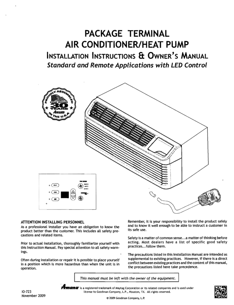
Amana REFURBISHED R-AMAP084AW User manual

Amana

Amana REFURBISHED R-AMAP084AW User manual

Amana 10c5ez Assembly instructions

Amana

Amana 10c5ez Assembly instructions

Amana AMAP081BW User manual

Amana

Amana AMAP081BW User manual

Amana MBVC Series Service manual

Amana

Amana MBVC Series Service manual

Amana AMAP121A User manual

Amana

Amana AMAP121A User manual

Amana TE09095W2B Manual

Amana

Amana TE09095W2B Manual

Amana DigiSmart PTC074E25AXXX Installation instructions

Amana

Amana DigiSmart PTC074E25AXXX Installation instructions

Popular Air Conditioner manuals by other brands

Coby CBPAC815 manual

Coby

Coby CBPAC815 manual

Mitsubishi Electric PUHZ-RP50VHA4 Service manual

Mitsubishi Electric

Mitsubishi Electric PUHZ-RP50VHA4 Service manual

Gree GWH18TC-K3DNA1B/I Service manual

Gree

Gree GWH18TC-K3DNA1B/I Service manual

Toshiba RAS-13SKHP-E Service manual

Toshiba

Toshiba RAS-13SKHP-E Service manual

Frigidaire FRS09PYW1 installation guide

Frigidaire

Frigidaire FRS09PYW1 installation guide

Challenge MPPHA-05CRN1-QB6 instruction manual

Challenge

Challenge MPPHA-05CRN1-QB6 instruction manual

LG LS-J0761CL Service manual

LG

LG LS-J0761CL Service manual

Carrier 38BA Installation, Start-Up and Service Instructions

Carrier

Carrier 38BA Installation, Start-Up and Service Instructions

Whynter ARC-12SDH instruction manual

Whynter

Whynter ARC-12SDH instruction manual

Samsung MH FSBA Series installation manual

Samsung

Samsung MH FSBA Series installation manual

LG A2UN186FA0 Service manual

LG

LG A2UN186FA0 Service manual

Mitsubishi Electric Mr. SLIM SLZ-M15FA2.TH Technical & service manual

Mitsubishi Electric

Mitsubishi Electric Mr. SLIM SLZ-M15FA2.TH Technical & service manual

Daikin Super Multi NX 3MKS50E3V1B Service manual

Daikin

Daikin Super Multi NX 3MKS50E3V1B Service manual

GE AEZ10AVL1 Owner's manual and installation instructions

GE

GE AEZ10AVL1 Owner's manual and installation instructions

Vogue 373008 Installation instructions & user guide

Vogue

Vogue 373008 Installation instructions & user guide

Frigidaire FFRE153WA1 Use & care guide

Frigidaire

Frigidaire FFRE153WA1 Use & care guide

LG HERCULES 2.0 S05LPBX-P owner's manual

LG

LG HERCULES 2.0 S05LPBX-P owner's manual

Yumpu YCP024F1L-M Installation operation & maintenance

Yumpu

Yumpu YCP024F1L-M Installation operation & maintenance

manuals.online logo
manuals.online logoBrands
  • About & Mission
  • Contact us
  • Privacy Policy
  • Terms and Conditions

Copyright 2025 Manuals.Online. All Rights Reserved.