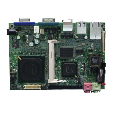
AMD Geode LX 800 User manual

USER'S MANUAL
Of
AMD Geode LX800
&
AMD CS5536 Chipset
Based
M/B For AMD Geode LX800 Processor
NO. G03-8F9-F
Rev2.0
Release date: March, 2008
Trademark:
* Specifications and Information contained in this documentation are furnished for information use only, and are
subject to change at any time without notice, and should not be construed as a commitment by manufacturer.

ii
Environmental Protection Announcement
Do not dispose this electronic device into the trash while discarding. To minimize pollution
and ensure environment protection of mother earth, please recycle.

iii
USER’S NOTICE .................................................................................................................................. iii
MANUAL REVISION INFORMATION............................................................................................ iii
ITEM CHECKLIST.............................................................................................................................. iii
CHAPTER 1 INTRODUCTION OF AMDCS5536 CHIPSET MOTHERBOARD
1-1 FEATURE OF MOTHERBOARD..................................................................................... 1
1-1-1 SPECICAL FEATURE OF MOTHERBOARD............................................................. 2
1-2 SPECIFICATION.................................................................................................................. 3
1-3 LAYOUT DIAGRAM & JUMPER SETTING................................................................... 4
CHAPTER 2 HARDWARE INSTALLATION
2-1 HARDWARE INSTALLATION STEPS............................................................................. 8
2-2 CHECKING MOTHERBOARD'S JUMPER SETTING.................................................. 8
2-3 GLOSSARY ........................................................................................................................... 10
2-4 INSTALL MEMORY............................................................................................................ 11
2-5 EXPANSION CARDS........................................................................................................... 12
2-5-1 PROCEDURE FOR EXPANSION CARD INSTALLATION............................ 12
2-5-2 ASSIGNING IRQ FOR EXPANSION CARD...................................................... 13
2-5-3 INTERRUPT REQUEST TABLE FOR THIS MOTHERBOARD.................... 14
2-6 CONNECTORS AND HEADERS ....................................................................................... 14
2-6-1 CONNECTORS....................................................................................................... 14
2-6-2 HEADERS ............................................................................................................... 17
2-7 STARTING UP YOUR COMPUTER ................................................................................. 20
CHAPTER 3 INTRODUCING BIOS
3-1 ENTERING SETUP.............................................................................................................. 23
3-2 GETTING HELP................................................................................................................... 23
3-3 THE MAIN MENU................................................................................................................ 23
3-4 STANDARD CMOS FEATURES........................................................................................ 25
3-5 ADVANCED BIOS FEATURES.......................................................................................... 27
3-6 ADVANCED CHIPSET FEATURES.................................................................................. 30
3-7 INTEGRATED PERIPHERALS......................................................................................... 32
3-8 POWER MANAGEMENT SETUP ..................................................................................... 33
3-8-1 IRQ WAKEUP EVENT.................................................................................................... 34
3-9 PNP/PCI CONFIGURATION SETUP............................................................................... 34
3-10 LOAD FAIL-SAFE DEFAULTS........................................................................................ 35
TABLE OF CONTENT
iv
3-11 LOAD OPTIMIZED DEFAULTS...................................................................................... 36
3-12 PASSWORD SETTINGS .................................................................................................... 36
CHAPTER 4 DRIVER & FREE PROGRAM INSTALLATION
MAGIC INSTALL SUPPORTS WINDOWS 2000/XP
4-1 VGA INSTALL AMD GEODE LX800 VGA DRIVER ........................................ 39
4-2 SOUND INSTALL REALTEK ALC665 CODEC AUDIO DRIVER........................ 40
4-3 LAN INSTALL REALTEK 8110SCETHERNET NIC DRIVER........................ 42
4-4 PC- CILLIN INSTALL PC-CILLIN 2006 ANTI-VIRUS PROGRAM ....................... 43
4-5 CRYPTO INSTALL CRYPTO ENCRYPTION/DECRYPTIONDRIVER...... 45
4-6 HOW TO UPDATE BIOS................................................................................................... 47
4-7 PRO MAGIC PLUS FUNCTION INTRODUCTION........................................................ 47
APPENDIX ................................................................................................................ 50
USER’S NOTICE
COPYRIGHT OF THIS MANUAL BELONGS TO THE MANUFACTURER. NO PART OF THIS MANUAL,
INCLUDING THE PRODUCTS AND SOFTWARE DESCRIBED IN IT MAY BE REPRODUCED,
TRANSMITTED OR TRANSLATED INTO ANY LANGUAGE IN ANY FORM OR BY ANY MEANS WITHOUT
WRITTEN PERMISSION OF THE MANUFACTURER.
THIS MANUAL CONTAINS ALL INFORMATION REQUIRED TO USE INTEL 945GM CHIPSET
MOTHER-BOARD SERIES AND WE DO ASSURE THIS MANUAL MEETS USER’S REQUIREMENT BUT WILL
CHANGE, CORRECT ANY TIME WITHOUT NOTICE. MANUFACTURER PROVIDES THIS MANUAL “AS IS”
WITHOUT WARRANTY OF ANY KIND, AND WILL NOT BE LIABLE FOR ANY INDIRECT, SPECIAL,
INCIDENTIALORCONSEQUENTIAL DAMAGES (INCLUDING DAMANGES FOR LOSS OF PROFIT, LOSS OF
BUSINESS, LOSS OF USE OF DATA, INTERRUPTION OF BUSINESS AND THE LIKE).
PRODUCTS AND CORPORATE NAMES APPEARING IN THIS MANUAL MAY OR MAY NOT BE
REGISTERED TRADEMARKS OR COPYRIGHTS OF THEIR RESPECTIVE COMPANIES, AND THEY ARE
USED ONLY FOR IDENTIFICATION OR EXPLANATION AND TO THE OWNER’S BENEFIT, WITHOUT
INTENT TO INFRINGE.

v
Manual Revision Information
Reversion Revision History Date
2.0 Second Edition March, 2008
Item Checklist
5AMD Geode LX800 & AMD CS5536 Chipset Based Motherboard
5Cable for IDE Port
5Optional USB Cable
5Optional Serial Port Cables
5CD for motherboard utilities
5AMD Geode LX800 & AMD CS5536 Chipset Based Motherboard User’s Manual

1
Chapter 1
Introduction of GEODE LX800 & AMD CS5536 Chipset Motherboards
1-1 Feature of motherboard
The GEODE LX800 & AMD CS5536 chipset motherboard series are designed for the new
generation AMD Geode™ processor family guaranteed both of the performance and stability
of general purpose IPC and dedicated IPC platform solutions. The GEODE LX800 & AMD
CS5536 chipset is fully optimized to provide the variety IPC platform solutions by featuring
the high compatibilities and cost-effective, low power consumption, high performance, and
superior core graphics engine.
high performance. The embedded AMD Geode™ LX family processor has evolved to meet
the specific requirements of extended temperature applications in telecommunications
infrastructure (including wired, wireless, and BSC/MSC), single board computing,
automotive and transportation systems and industrial control and monitoring.
The GEODE LX800 & AMD CS5536 chipset motherboard series support 133MHz Front
Side Bus and provide 166MHz / 200MHz Memory clock frequency for DDR 333/400 system
RAM Modules which is expandable to 1.0GB. The GEODE LX800 & AMD CS5536 chipset
motherboard offers 2.5 inch ULTRA ATA 100 HDD that increases the performance of whole
system. The Realtek RTL8110SC Ethernet compatible PCI LAN which supports the Fast
Ethernet LAN function of 10 / 100Mb/s data transfer rate for internet or intranet connections.
The motherboard series are also integrated Realtek ALC655 AC’97 2-channel Audio CODEC
on system which is fully compatible with Sound Blaster Pro®that gives you the best sound
quality and compatibility.
The integrated superior core graphics engine supports MMX and AMD 3DNow! Technology
instruction sets and offers exceptional playback and streaming of various digital video formats
while maintaining ultra low power consumption and exerting minimal load on the processor.

2
It also provides extensive display support with outputs to High-resolution CRT outputs
(simultaneous operation) with support for High Definition (HD) and Standard Definition (SD)
standards and support for 1920x1440 in CRT mode.
Embedded 4 USB2.0 functional ports delivering 480Mb/s data transfer rate, these
motherboards meet USB2.0 demands data transport demands which are also equipped with
hardware monitor function on system to monitor and protect your system and maintain your
non-stop business computing.
Targets at High Growth Markets: Digital Home / Digital Office / Digital World
-Personal electronics such as personal video recorders (PVR), set top boxes, home theatres,
digital audio centers, etc.
-Mini PCs / Green clients / Quiet desktop PCs / High density servers
-Home server appliances / Public information/entertainment kiosks / Point-of-Sales
systems / Intelligent displays / Edge networking devices / Hospital monitoring systems /
Municipal control & monitoring systems
1-1.1 Special Feature of motherboard
OC-CON ---(High-polymer Solid Electrolysis Aluminum Capacitors)
The working temperature is from 55 degrees Centigrade below zero to 125 degrees
Centigrade, OC-CON capacitors possess superior physical characteristics that can be while
reducing the working temperature between 20 degrees Centigrade each time, intact extension
10 times of effective product operation lives, at not rising degrees Centigrade of working
temperatures each time a relative one, life of product decline 10% only too.

3
1-2 Specification
Spec Description
Design ∗Nano ITX form factor 6 layers PCB size: 12.0x12.0cm
Chipset ∗Northbridge: AMD Geode LX800
∗Southbridge: AMD CS5536 Chipset
Embedded CPU
∗Support 133MHz Front Side Bus AMD Geode™ LX800
processor up to 533 MHz
∗Low Power Consumption and Fanless
∗Socket-A AMD Geode™ LX Series processor utilizing BGA481
package.
∗64K L1 and 128K L2 Cache
Memory Socket
∗200-pin DDR SODIMM socket x1
∗Support DDR 400/333 system RAM Modules DDR memory
∗Expandable to 1GB.
x
Integrated VGA
∗Integrated FPU that support MMX and AMD 3DNow!
Technology instructions sets
∗9 GB/s internal Geode Link technology Interface Unit(GLIU)
∗High-resolution CRT outputs
∗VESA 1.1 and 2.0 VIP/VDA support
x
Expansion Slots ∗32-bit Mini-PCI slot x 1pcs
Integrate IDE ∗One PCI IDE controller that supports PCI Bus Mastering, ATA
PIO/DMA and the ULTRA DMA 33/66/100 functions that
deliver the data transfer rate up to 100 MB/s;
LAN
∗Integrated Realtek RTL8110SC PCI 10 / 100 / 1000 LAN.
∗Support Fast Ethernet LAN function of providing 10Mb/100Mb
data transfer rate

4
Audio ∗Realtek ALC655 AC97’4-channel Audio Codec integrated
∗Audio driver and utility included
BIOS ∗Award 4MB LPC Flash ROM
Multi I/O
∗PS/2 keyboard Connector
∗D-Sub 15-pin VGA Conn.x1
∗USB 2.0 connector x 2, USB2.0 header x1
∗Serial port header x4
∗2-channel Audio connector (Line-out, MIC)
1-3 Layout Diagram & Jumper Setting
MIC-IN
Line-Out
VGA Gi
g
abit LAN
Power Conn. USB

5
AMD Geode LX800
Processor
AMD
CS 5539
Chipset
USB Port
(USB1)
VGA Conn.
LAN Connector
CN1
J2
ATA100
IDE Connector
VGA_CN
J3
COM
USB Port Connector
2-CH Audio
Connector
RTL
8110SC
PCI LAN
COM
JP1
12V CN
Power On/Off
Reset
Keyboard
Connector
ALC 665
AUDIO CODEC
Compact Flash slot

6
200-pin DDR SODIMM
4MB Flash ROM BIOS
Mini PCI Slot

7
Jumper Name Description Page
J1 ATX/AT Mode selecte 3-pin Block p.9
J2 CMOS RAM Clear Function Setting 3-pin Block p.9
J3 CF Card Master/Slave Mode Select 2-pin Block p.10
Connectors
Connector Name Description Page
CN1 Nano-ITX Power Connector 1Phone Jack p.13
12V CN 12V Power Connector 4-pin Block p.13
VGA CN VGA Power Connector 22-pin Block p.13
JUSB1 USB Port Connector 4-pin Connector p.14
LAN1 RJ45 LAN Connector 4-pin Connector p.14
VGA1 VGA Port Connector 15-pin Female p.14
CN4 Line-Out /MIC Audio Connector 2 Phone Jack p.14
PS2 KB PS2 Keyboard Connector 5-PinConnector p.14
CF Compact Flash Card 50-pin Expansion Socket p.14
Headers
Header Name Description Page
USB1 USB2.0 Port Headers 9-pin Block p.15
J11 44-Pin Connector 44-pin Block p.15
RESET Reset switch lead 2-pin Block p.15
PWR BTN Power Button Headers 2-pin Block p.15
COM1/COM2
COM3/COM4 Serial Port Headers 9-pin Female p.16
Expansion Sockets
Socket/Slot Name Description Page
DDR DDR SDRAM Module
Socket 200-pin DDR SODIMM Module
Expansion Socket p.11
Mini PCI Mini PCI Slot 124-Pin Mini PCI Local Bus Expansion slots p.12

8
Chapter 2
Hardware installation
2-1 Hardware installation Steps
Before using your computer, you had better complete the following steps:
1. Check motherboard jumper setting
2. Install CPU and Fan
3. Install System Memory (DIMM)
4. Install Expansion cards
5. Connect IDE, Front Panel /Back Panel cable
6. Connect Nano-ITX Power cable
7. Power-On and Load Standard Default
8. Reboot
9. Install Operating System
10. Install Driver and Utility
2-2 Checking Motherboard’s Jumper Setting
(1) ATX/AT Mode Selected (3-pin):JP1
J1 is used to select from ATX/ AT mode.
1-2 AT mode(Default)
2-3 ATX mode
JP1
JP1 1
3
1
3

9
(2) CMOS RAM Clear (3-pin): J2
A battery must be used to retain the motherboard configuration in CMOS RAM short 1-2
pins of JPAT to store the CMOS data.
To clear the CMOS, follow the procedure below:
1. Turn off the system and unplug the AC power
2. Remove ATX power cable from ATX power connector
3. Locate JBAT and short pins 2-3 for a few seconds
4. Return JBAT to its normal setting by shorting pins 1-2
5. Connect ATX power cable back to ATX power connector
Note: When should clear CMOS
1. Troubleshooting
2. Forget password
3. After over clocking system boot fail
CMOS RAM Clear Setting
2-3 closed Clear CMOS
J2 J2
1-2 closed Normal (Default)
1
3
1
3

10
(3) CF Card Master/Slave Mode(2-Pin)J3
CF Card Master/Slave Mode
Slave
J3 1
2
J3 1
2
Master
2-3 Glossary
Chipset (core logic) - two or more integrated circuits which control the interfaces between
the system processor, RAM, I/O devises, and adapter cards.
Processor socket - the socket used to mount the system processor on the motherboard.
Slot (AGP, PCI, ISA, RAM) - the slots used to mount adapter cards and system RAM.
PCI - Peripheral Component Interconnect - a high speed interface for video cards, sound
cards, network interface cards, and modems; runs at 33MHz.
Serial Port - a low speed interface typically used for mouse and external modems.
Parallel Port - a low speed interface typically used for printers.
PS/2 - a low speed interface used for mouse and keyboards.
USB - Universal Serial Bus - a medium speed interface typically used for mouse, keyboards,
scanners, and some digital cameras.
Sound (interface) - the interface between the sound card or integrated sound connectors and
speakers, MIC, game controllers, and MIDI sound devices.
BIOS (Basic Input/Output System) - the program logic used to boot up a computer and
establish the relationship between the various components.
Driver - software, which defines the characteristics of a device for use by another device or
other software.
Processor - the "Central Processing Unit" (CPU); the principal integrated circuit used for

11
doing the "computing" in "personal computer"
Front Side Bus Frequency - The working frequency of the motherboard, which is generated
by the clock generator for CPU, DRAM and PCI BUS.
CPU L2 Cache - The flash memory inside the CPU, normally Pentium III CPU has 256K or
above, while Celeron CPU will have 128
2-4 Install Memory
The motherboards provide one 200-pin SMALL OUTLINE DUAL INLINE MEMORY
MODULES (SODIMM) sites for memory expansion available from minimum memory size
of 64MB to maximum memory size of 1.0GB DDR SDRAM.
Valid Memory Configurations
Bank 200-Pin DIMM PCS Total Memory
Bank 0, 1 (DDR1) DDR 400/DDR333/ DDR 266
DDR SDRAM Module
X1 64MB∼1.0GB
Total System Memory (Max. 1.0GB) 1 64MB∼1.0GB
Generally, installing SODDR SDRAM modules to your motherboard is very easy; you can
refer to figure 2-4 to see what a 200-Pin DDR 333 / DDR 266 DDR SDRAM module looks
like.

12
NOTE! When you install DIMM module fully into the DIMM socket the eject tab should be
locked into the DIMM module very firmly and fit into its indention on both sides.
WARNING! For the DDR SDRAM CLOCK is set at 166MHz, use only DDR333-compliant DDR
Modules. When this motherboard operate at 133MHz, most system will not even
boot if non-compliant modules are used because of the strict timing issues, if your
SDR Modules are not DDR333-compliant, set the DDR SDRAM clock to 133MHz
to ensure system stability.
2-5 Expansion Cards
WARNING! Turn off your power when adding or removing expansion cards or other system
components. Failure to do so may cause severe damage to both your
motherboard and expansion cards.
2-5-1 Procedure For Expansion Card Installation
1. Read the documentation for your expansion card and make any necessary hardware or
software setting for your expansion card such as jumpers.
2. Remove your computer’s cover and the bracket plate on the slot you intend to use.
3. Align the card’s connectors and press firmly.
4. Secure the card on the slot with the screen you remove above.
Press down
firmly
Plug the golden
figure into the
slot

13
5. Replace the computer system’s cover.
6. Set up the BIOS if necessary.
7. Install the necessary software driver for your expansion card.
2-5-2 Assigning IRQs For Expansion Card
Some expansion cards need an IRQ to operate. Generally, an IRQ must exclusively assign
to one use. In a standard design, there are 16 IRQs available but most of them are already in
use.
Standard Interrupt Assignments
IRQ Priority Standard function
0 N/A System Timer
1 N/A Keyboard Controller
2 N/A Programmable Interrupt
3 * 8 Communications Port (COM2)
4 * 9 Communications Port (COM1)
5 * 6 Sound Card (sometimes LPT2)
6 * 11 Floppy Disk Controller
7 * 7 Printer Port (LPT1)
8 N/A System CMOS/Real Time Clock
9 * 10 ACPI Mode when enabled
10 * 3 IRQ Holder for PCI Steering
11 * 2 IRQ Holder for PCI Steering
12 * 4 PS/2 Compatible Mouse Port
13 N/A Numeric Data Processor
14 * 5 Primary IDE Channel
15 * 1 Secondary IDE Channel
* These IRQs are usually available for ISA or PCI devices.

14
2-5-3 Interrupt Request Table For This Motherboard
Interrupt request are shared as shown the table below:
INT A INT B INT C INT D INT E INT F INT G INT H
Slot 1 √
Onboard VGA √
Onboard USB 1 √
Onboard USB 2 √
LAN √
AC97/MC97 √
IMPORTANT! If using PCI cards on shared slots, make sure that the drivers support “Shared
IRQ” or that the cards don’t need IRQ assignments. Conflicts will arise between
the two PCI groups that will make the system unstable or cards inoperable.
2-6 Connectors and Headers
2-6-1 Connectors
(1) CN1: Power Jack
The motherboard power is supplied from a power jack. This is a newly defined
connector connecting the power adapter which provides DC12V +/- power for the
motherboard. The Power Supply allows using soft power on momentary switch that
connect from the front panel switch to 2-pins Power On jumper pole on the
motherboard. When the power switch on the back of the power supply turned on, the
full power will not come into the system board until the front panel switch is
momentarily pressed. Press this switch again will turn off the power to the system
board.

15
(2) 12V Power Connector (4-pin block):12VCN
This is a newly defined 4-pins connector support extra 12V voltage to maintain system
power consumption in the case that an AD-Scalar daughter board is used. Without this
connector might cause system unstable because the power supply can not provide
sufficient current for system.
(3) VGA Power Connector: VGA _CN
This connector is ready for an AD-Scalar daughter board.
Pin
1
12VCN
Other manuals for Geode LX 800
1
This manual suits for next models
2
Table of contents
Other AMD Computer Hardware manuals

AMD
AMD AX1800DMT3C - Athlon XP 1.53 GHz Processor User manual

AMD
AMD ATHLON 8 User manual

AMD
AMD SP5100 Product guide

AMD
AMD 780E Product manual

AMD
AMD Geode LX CS5536 User manual

AMD
AMD Geode SC1200 Product guide

AMD
AMD Athlon XP 10 User manual

AMD
AMD XILINX T2 Telco User manual

AMD
AMD Geode LX [email protected] Product guide

AMD
AMD 3200 - Athlon 64 2.0 GHz Processor User manual