26633 Rev. 3.03 September 2003 AMD Athlon™ 64 and AMD Opteron™ Processors Thermal
Design Guide
List of Figures
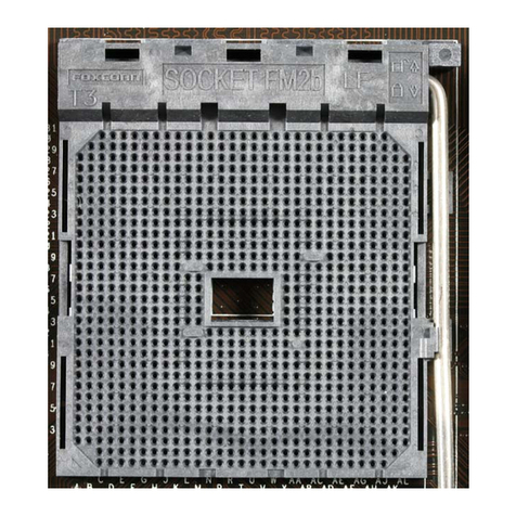
Figure 1. 754-pin µPGA Socket Used for the AMD Athlon™ 64 Processor..................................14
Figure 2. 940 pin µPGA Socket Used for the AMD Opteron™ Processor .....................................15
Figure 3. Motherboard Component Height Restrictions for the AMD Athlon 64 Processor
Thermal Solution ..............................................................................................................16
Figure 4. Motherboard Component Height Restrictions for the AMD Opteron Processor
Thermal Solution ..............................................................................................................17
Figure 5. AMD Athlon 64 and AMD Opteron Processors Thermal Reference Design
Solution 1 .........................................................................................................................20
Figure 6. Thermal Reference Design Solution 1 Components Assembled for Shipment ...............21
Figure 7. View of an Installed Heatsink Utilizing the Thermal Reference Design
Solution 1 .........................................................................................................................21
Figure 8. Exploded View of the Components Utilized in the AMD Athlon 64 and
AMD Opteron Processors Thermal Reference Design Solution 2..................................23
Figure 9. Thermal Reference Design Solution 2 Components Configured for Shipment ...............24
Figure 10. View of a Heatsink Installation Utilizing the Thermal Reference Design
Solution 2 ......................................................................................................................24
Figure 11. Example of a Low-Cost Heatsink Using Aluminum Extrusion Technology.................27
Figure 12. High Performance Heatsink with Copper Slug Embedded in the Base .........................28
Figure 13. Required Exhaust Airflow Direction for Motherboard Voltage Regulator
Cooling...........................................................................................................................29
Figure 14. Typical Temperature-Fan Speed Relation for Speed-Controlled Fan............................31
Figure 15. Acoustic Noise from Sample Thermal Solutions with a 70x15 mm Fan.......................32
Figure 16. Diagonals Marked on Processor to Locate Center .........................................................37
Figure 17. Thermocouple Taped to Processor Lid...........................................................................38
Figure 18. Thermocouple Attached to Processor with Strain Relief on Package and PCB.............39
Figure 19. Heatsink with Thermocouple Relief Groove Machined into Base.................................39
Figure 20. Heatsink Thermocouple Relief Groove and Measurement Hole ...................................40
Figure 21. An Entran ELW-D1 Load Cell.......................................................................................41
Figure 22. Load Cell Inserted into the Load Cell Fixture................................................................42
Figure 23. Drawing of Load Cell Fixture for the Entran ELW-D1 Load Cell ................................43
Figure 24. Test Board with a Load Cell Fixture Installed in the Socket 754 ..................................45
Figure 25. Heatsink Installation over the Load Cell Fixture ...........................................................46
List of Figures 5
