AMD SD188ES User manual

1.1
SD188ES/SD188EM Demonstration Board User’s Manual vii
About the SD188ES/SD188EM
Demonstration Board
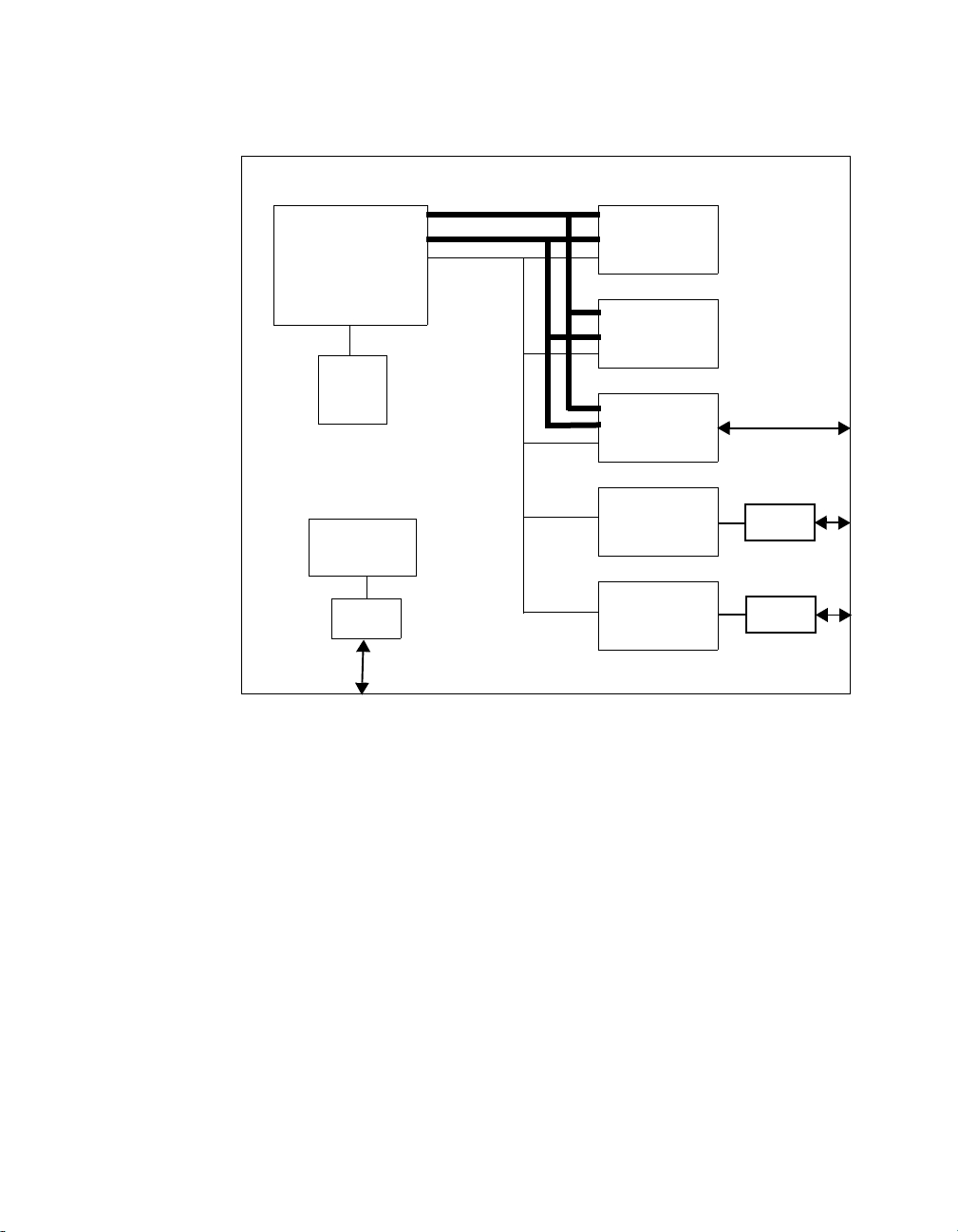
The AMD®SD188ES/SD188EM Demonstration Board is designed as an
exceptionally small, low-cost product for demonstration of the AMDAm188ES
and Am188EM microcontrollers. See page ix for a block diagram of the board.
The SD188ES/SD188EM demonstration board is a stand-alone evaluation
platform for the Am188ES or Am188EM microcontroller. The Am188ES and
Am188EM microcontrollers integrate peripherals such as 12 chip-select
controllers, serial controllers, 32 programmable I/Os, three timers, an interrupt
controller, and watchdog timer to increase system functionality while reducing
overall cost. The memory controller supports a glueless connection to SRAM,
EPROM, Flash memory, and pseudo-static RAM. The Am188ES and Am188EM
microcontrollers also feature an innovative bus design that frees the processor to
run at nearly twice the speed of standard 80C188 processors while using
commodity memory devices.
TheSD188ES/SD188EM demonstrationboardisdesigned witha 104-pinAm188
expansion interface that provides access to the Am188ES and Am188EM
microcontrollers signals. The Am188 expansion interface facilitates prototyping
with external devices by using the SD188ES/SD188EM demonstration board as
the minimal system core of a design.
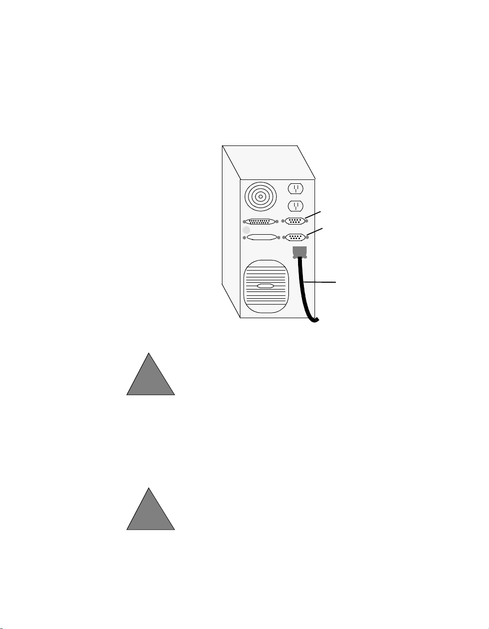
The SD188ES/SD188EM demonstration board highlights the Am188ES and
Am188EM microcontrollers’ serial ports, glueless interface to SRAM and Flash
memory, and the expansion interface to peripheral attachments. A complete
description of the board can be found in Chapter 2, “Demonstration Board
Functional Description”.
frtbook : about1 Page vii Monday, June 2, 1997 3:37 PM

SD188ES/SD188EM Demonstration Board User’s Manual
viii
1.1
Theory of Operation
The SD188ES/SD188EM demonstration board demonstrates the basic processor
functionality and features of the Am188ES and Am188EM microcontrollers, and
the simplicity of their system design. As a stand-alone platform, the board enables
you to test the Am188ES and Am188EM microcontrollers’ performance and
functionality. The minimal number of components on the board exhibits the
integration present in the processor.
Demonstration Board Features
The SD188ES/SD188EM demonstration board provides the following features:
• Am188ES or Am188EM 40-MHz microcontroller
•E86
™
family boot monitor (E86MON) board-resident utility
Information on invoking and using the E86MON software is provided in the
E86MONTM Software User’s Manual included in your kit.
• 128 Kbyte SRAM
• 128 Kbyte Am29F010-70 Flash memory
• Am188 104-pin expansion interface
• Two RS-232 serial ports with DB-9 connectors
Please note that the Am188EM microcontroller provides one asynchronous
serial port. Thus, when the board is populated with the Am188EM
microcontroller, only one serial port is featured.
• Activity LED indicators for PIO signals
• Power-on LED indicator
• Reset circuitry
frtbook : about1 Page viii Monday, June 2, 1997 3:37 PM

SD188ES/SD188EM Demonstration Board User’s Manual ix
1.1
Figure 0-1. SD188ES/SD188EM Demonstration Board Block Diagram
Address Bus
A/D Bus
Control
Am188ES or Am188EM
Microcontroller
CPU
Clock &
Reset
Circuitry
Power
& Ground
5.5-mm
Barrel
Connector
Am29F010-70
Flash Bank
(128 Kbyte)
SRAM Bank
(128 Kbyte)
Am188
Expansion
Interface
RS-232 Serial Port
Level Converter
Circuitry DB-9
Connector
RS-232 Serial Port
Level Converter
Circuitry*
DB-9
Connector*
*Second asynchronous serial port implemented only
with Am188ES microcontroller
frtbook : about1 Page ix Monday, June 2, 1997 3:37 PM

SD188ES/SD188EM Demonstration Board User’s Manual
x
1.1
SD188ES/SD188EM Demonstration Board
Documentation
The SD188ES/SD188EM Demonstration Board User’s Manual provides
informationon thedesign andfunctionof the SD188ES/SD188EMdemonstration
board. Detailed instructions for using the E86MON software are provided in the
E86MONTMSoftwareUser’sManualincludedinyourkit.Thedemonstrationboard
is shipped with the E86MON software installed in the on-board Flash memory.
About This Manual
Chapter 1, “Quick Start” provides implementation and installation information for
the demonstration board and instructions for invoking the E86MON software.
DetailedinformationonusingtheE86MONsoftwareisprovidedintheE86MONTM
Software User’s Manual included in your kit.
Chapter 2, “Demonstration Board Functional Description” contains descriptions
of the basic sections of thedemonstration board: layout, processor, Flash memory,
SRAM, serial ports, power and signal LED indicators, clock and reset logic,
expansion interface, and power-supply circuitry.
Chapter3,“ProductSupport”providesinformationonreachingandusingtheAMD
Corporate Applications technical support services, product information available
throughAMD’sWorldWideWebandFTPsites,andsupporttoolsfortheembedded
E86 family.
AppendixA,“LayoutDiagram,Schematics,andBoardBillof Materials”contains
a board layout drawing along with schematics and a Bill of Materials (BOM) for
the SD188ES/SD188EM demonstration board.
frtbook : about1 Page x Monday, June 2, 1997 3:37 PM

SD188ES/SD188EM Demonstration Board User’s Manual xi
1.1
Suggested Reference Material
For information on ordering the literature listed below, see Chapter 3, “Product
Support”.
•Am186ES and Am188ES Microcontrollers Data Sheet
Advanced Micro Devices, order number 20002
•Am186EM and Am188EM Microcontrollers Data Sheet
Advanced Micro Devices, order number 19168
•Am186EM and Am188EM Microcontrollers User’s Manual
Advanced Micro Devices, order number 19713
•Am186ES and Am188ES Microcontrollers User’s Manual
Advanced Micro Devices, order number 21096
•Am186and Am188Family Instruction Set Manual
Advanced Micro Devices, order number 21267
•FusionE86SM Catalog
Advanced Micro Devices, order number 19255
• For current application notes and technical bulletins, see our World Wide Web
page at http://www.amd.com.
frtbook : about1 Page xi Monday, June 2, 1997 3:37 PM

SD188ES/SD188EM Demonstration Board User’s Manual
xii
1.1
Documentation Conventions
The Advanced Micro Devices SD188ES/SD188EM Demonstration Board User’s
Manual uses the conventions shown in Table 0-1 (unless otherwise noted). These
same conventions are used in all E86 family support product manuals.
Table 0-1. Notational Conventions
Symbol Usage
Boldface Indicates that characters must be entered
exactly as shown, except that the alphabetic case is
only significant when indicated.
Typewriter face Indicatescomputertextinputoroutputinanexample
or listing.
frtbook : about1 Page xii Monday, June 2, 1997 3:37 PM

1.1
SD188ES/SD188EM Demonstration Board User’s Manual 1-1
Chapter 1
Quick Start
This chapter provides information that will help you quickly set up and start using
the SD188ES/SD188EM demonstration board.
The SD188ES/SD188EM demonstration board is supported by the E86MON
software. The E86MON software enables you to load, run, and debug programs
on the SD188ES/SD188EM demonstration board. For detailed information on
using the E86MON software, refer to the E86MONTM Software User’s Manual
included in your kit.
For information on how to:
• Connect the SD188ES/SD188EM demonstration board to a PC, see page 1-2
• Invoke the E86MON software, see page 1-4
• Troubleshoot installation problems, see page 1-5
• Locate related sources of information, see page 1-6
frtbook : ch1 Page 1 Monday, June 2, 1997 3:37 PM

SD188ES/SD188EM Demonstration Board User’s Manual
1-2
1.1
Connecting to a PC
Follow the steps below to connect the SD188ES/SD188EM demonstration board
to your PC.
Installation Requirements
The items listed below are necessary to install and run the SD188ES/SD188EM
demonstration board:
• PC with an available COM port
• Terminal emulation software (such as Microsoft Windows®Terminal or
ProComm Plus) that supports ASCII file transfers, software flow control (Xon/
Xoff), and send break capability
• Power source for universal power supply
Board Installation
1. Removetheboardfromtheshippingcarton.Visuallyinspecttheboardtoverify
that it was not damaged during shipment.
!CAUTION: As with all computer equipment, the
SD188ES/SD188EM demonstration board may be
damaged by electrostatic discharge (ESD). Please take
proper ESD precautions when handling any board.
frtbook : ch1 Page 2 Monday, June 2, 1997 3:37 PM

SD188ES/SD188EM Demonstration Board User’s Manual 1-3
1.1
2. Connect the demonstration board’s DB-9 serial port (either P1 or P0 on the ES
version of the board; P1 on the EM version of the board) to an available COM
port. Use the serial cable included in the SD188ES/SD188EM demonstration
board kit and note that a DB-9 to DB-25 serial connector adapter is provided
if your host system requires it. The pinout of the demonstration board’s serial
connector is shown on page 2-9.
3. Connect the power supply to the barrel connectoron the SD188ES/SD188EM
demonstration board.
4. Applypowertotheboardbyconnectingthepowersupplytoanelectricaloutlet.
Once the board is powered up, the LEDs (CR3-CR10) should flash in an
oscillating pattern.
COM1
COM2
serial
cable
!DANGER:Makesurethepowersupplyisnotpluggedinto
an electrical outlet before connecting it to the SD188ES/
SD188EM demonstration board
!CAUTION: If using your own power supply, ensure that
it is a 5-V supply with the proper polarity (see page 2-14).
Using a 9-V supply will permanently damage the board.
frtbook : ch1 Page 3 Monday, June 2, 1997 3:37 PM

SD188ES/SD188EM Demonstration Board User’s Manual
1-4
1.1
5. Invoke the terminal emulation program at 19200 baud, no parity, 8 data bits, and 1
stop bit; enable the software flow control (Xon/Xoff), if supported.
6. Reset the board by depressing and releasing the RESET switch (see location in
Figure 2-1 on page 2-3). The LEDs on the board (CR3-CR10) will again flash in
an oscillating pattern for three seconds, as they did upon power up.
During the three-second period while the LEDs are oscillating, type an ain the
terminal window to ensure that the E86MON software uses the correct baud rate.
When the E86MON software receives an a, it adjusts its baud rate (if necessary)
and displays the welcome message and prompt.
If you type a character other than an a, or type no character at all, the E86MON
software still displays the welcome message and prompt, but may be using an
incorrect baud rate. Depressing and releasing the RESET switch gives you another
opportunity to type an a.
7. To display the version of the E86MON software and the commands available, type
?and press Enter.
For detailed information on using the E86MON software, refer to the E86MONTM
Software User’s Manual included in your manual.
frtbook : ch1 Page 4 Monday, June 2, 1997 3:37 PM

SD188ES/SD188EM Demonstration Board User’s Manual 1-5
1.1
Table 1-1. Installation Troubleshooting
Problem Solution
Nothing happens when
pushing the RESET
button.
Sometimes it is difficult to make a good
connection when pushing the small RESET
button. If all else fails, remove the power supply
from the AC electrical outlet and disconnect and
reconnect the power supply. The LEDs will flash
in an oscillating pattern when the reset is
successful.
The computer does not
respondwiththeE86MON
software prompt.
ResettheboardbypressingtheRESETswitchand
typing an awhile the LEDs are flashing in an
oscillatingpattern.Ifthisdoesnotwork,verifythe
power, check the cables, etc.
Aftertypingaduringreset,
the terminal emulation
software displays
unreadable characters.
Check the baud rate setting for the terminal
emulationsoftware.Itshouldbesetto19200.Also
checkthewordlength(8),stopbits(1),parity(N),
and turn off any hardware flow control.
Aftera processorreset, the
LEDs do not flash in the
expected oscillating
pattern.
Check that the power LED is on and the correct
voltage is supplied to the board. Ensure that the
polarity of the power connector is correct.
The terminal emulation
program locks up the
software or PC.
Check the COM port connection with the target
board. Make sure that the same COM port is
selected in the terminal emulation software. In
somePCsifthecorrectCOMportisnotspecified,
the software will fail to function—it will lock in
a continuous loop waiting for an answer from the
incorrect serial port.
The power LED does not
turn on with power. Immediatelydisconnectthepowersupply.Ensure
thatthepolarityofthe powerconnector is correct.
This is a very serious failure of the hardware. If
the power source is connected incorrectly, the
board will be permanently damaged.
There is a problem you
cannot resolve. Contact the AMD Corporate Applications
technical support services. (See Chapter 3,
"Product Support" for phone numbers and more
information.)
frtbook : ch1 Page 5 Monday, June 2, 1997 3:37 PM

SD188ES/SD188EM Demonstration Board User’s Manual
1-6
1.1
For More Information...
If you need more information about:
• SD188ES/SD188EM demonstration board hardware,
see Chapter 2,“Demonstration Board Functional Description”
• E86MON software,
see the E86MONTM Software User’s Manual
• Problems with the board or the E86MON software,
see Chapter 3,“Product Support”
• SD188ES/SD188EM demonstration board layout and schematics,
see Appendix A,“Layout Diagram, Schematics, and Board Bill of Materials”
• the Am188ES microcontroller
see the Am186ES and Am188ES Microcontrollers Data Sheet
• the Am188EM microcontroller,
see the Am186EM and Am188EM Microcontrollers Data Sheet
frtbook : ch1 Page 6 Monday, June 2, 1997 3:37 PM

1.1
SD188ES/SD188EM Demonstration Board User’s Manual 2-1
Chapter 2
Demonstration Board
Functional Description
TheSD188ES/SD188EM demonstrationboardprovidesa completelystand-alone
microcontroller-basedevaluationplatforminalow-cost,exceptionallysmallform-
factor product. The SD188ES/SD188EM demonstration board was designed to
meet the needs of customers working with the Am188ES and Am188EM
microcontrollers.
Read the following sections to learn more about the SD188ES/SD188EM
demonstration board hardware:
• “Layout and Placement” on page 2-2
• “Am188ES and Am188EM Microcontroller Implementation” on page 2-4
• “ROM Space” on page 2-7
• “SRAM” on page 2-7
• “RS-232 Serial Ports” on page 2-8
• “Clock and Reset Logic” on page 2-10
• “Am188 Expansion Interface” on page 2-10
• “PIO Activity LED Indicators” on page 2-13
• “Power Supply” on page 2-14
frtbook : newch2 Page 1 Monday, June 2, 1997 3:37 PM

SD188ES/SD188EM Demonstration Board User’s Manual
2-2
1.1
Layout and Placement
The design of the SD188ES/SD188EM demonstration board emphasizes ease of
use and small size. Refer to Figure 2-1 on page 2-3 for board layout and component
placement.
The SD188ES/SD188EM demonstration boardhas the Flash andSRAM memory
devices (U4 and U3) directly below the processor. This placement keeps the
memory devices as close as possible to the processor to minimize noise and trace
reflections. The 40-MHz fundamental mode crystal (Y1) is located to the right of
the processor. The expansion interface (J2 and J3) is located at the bottom of the
board for easy connection and access. Finally, the 5.5-mm power-supply barrel
connector (J1) is positioned in the upper, left corner of the board.
The RS-232 serial interfaces are positioned on the right of the board. Please note
that the ES version of the board features two serial ports (P0 and P1), which are
drivenbythetwoasynchronousserialinterfacesontheAm188ESmicrocontroller.
The Am188EM microcontroller provides one asynchronous serial interface so the
EM version of the board implements the serial port with a DB-9 connector (P1).
Table 2-1. SD188ES/SD188EM Demonstration Board Parts List
Part
Number Description For more
information, see
CR1–CR10 Power and signal LEDs Page 2-13
J1 Power connector Page 2-14
J2-J3 Expansion interface Page 2-10
U1 Voltage supply supervisor (TI TL7705A) Page 2-10
U2 Am188ES or Am188EM 40-MHz
microcontroller Page 2-4
U3 Flash memory Page 2-7
U4 SRAM Page 2-7
U5–U6 RS-232 driver/receiver devices (MAX232) Page 2-8
Y1 40-MHz fundamental mode crystal Page 2-10
frtbook : newch2 Page 2 Monday, June 2, 1997 3:37 PM

SD188ES/SD188EM Demonstration Board User’s Manual 2-3
1.1
Notes:
1.On the SD186ES demonstration board, P1 is asynchronous serial port 0; P0 is
asynchronous serial port 1.
2.On the SD186EM demonstration board, P1 is an asynchronous serial port;
P0 does not exist.
Figure 2-1. SD188ES/SD188EM Demonstration Board Layout
Reset
U6
POWER
CR3
CR4
CR5
CR6
CR7
CR8
CR9
CR10
Y1
132
019
B
A
C
D
SW1 U1
U2
U5
CR1
CR2
P0
U3 U4
FLASH SRAM
J2
J3
Advanced
Micro
Devices
Advanced
Micro
Devices
Advanced
Micro
Devices
Am188EM-40VC
SD188ES/EM
DEMO BOARD
P1 ES/EM
ES Only
GND
frtbook : newch2 Page 3 Monday, June 2, 1997 3:37 PM

SD188ES/SD188EM Demonstration Board User’s Manual
2-4
1.1
Am188ES and Am188EM Microcontrollers
Implementation
The SD188ES/SD188EM demonstration board supports the AMD Am188ES and
Am188EM microcontrollers. The board is shipped with either an Am188ES or
Am188EM microcontroller that operates at 40 MHz. Although not supported by
the on-board crystal, the Am188ES and Am188EM microcontrollers are also
available in 20-, 25-, and 33-MHz operating frequencies.
The Am188ES and Am188EM microcontrollers are designed to meet the most
common requirements of embedded products developed for the communications,
office automation, mass storage, and general embedded markets. Specific
applicationsincludefeaturephones,cellularphones,PBXs,multiplexers,modems,
disk drive controllers, hand-held and desktop terminals, fax machines, line cards,
managed hubs, and industrial control. Refer to the Am186ES and Am188ES
Microcontrollers Data Sheet and the Am186EM and Am188EM
Microcontrollers Data Sheet for more information on the specific features of the
Am188ES and Am188EM microcontrollers.
See Figure 2-2 on page 2-5 for a block diagram detailing the Am188ES
microcontroller’s functionality. See Figure 2-3 on page 2-6
for a block diagram
detailing the Am188EM microcontroller’s functionality.
frtbook : newch2 Page 4 Monday, June 2, 1997 3:37 PM

SD188ES/SD188EM Demonstration Board User’s Manual 2-5
1.1
Figure 2-2. Am188ES Microcontroller Block Diagram
S2-S0
Interrupt
Control Unit
Timer Control Unit DMA
Unit
Bus
Interface
Unit
Execution
Unit Chip-Select
Unit
Clock and
Power
Management
Unit
Control
Registers
16-Bit Count
Registers
Max Count A
Registers 16-Bit Count
Registers
20-BitDestination
Pointers
20-Bit Source
Pointers
Control
Registers
Control
Registers
Control
Registers
01(WDT)2 01
Max Count B
Registers
Refresh
Control
Unit
Control
Registers Control
RegistersControl
Registers
CLKOUTB
CLKOUTA INT6-INT4
INT3/INTA1/IRQ
INT2/INTA0
INT1/SELECT
INT0 TMROUT0 TMROUT1DRQ0 DRQ1
VCC
GND
TMRIN0 TMRIN1
ARDY
SRDY
DT/R
DEN/DS
HOLD
HLDA
Asynchronous
Serial Port 0
TXD0
RXD0
NMI
A19-A0
AD7-AD0
ALE
RFSH2/ADEN
WR
WB
RD
RES
LCS/ONCE0
MCS2-MCS0
PCS6/A2
PCS3-PCS0
PCS5/A1
UCS/ONCE1
X2
X1
PSRAM
Control
Unit
MCS3/RFSH
PIO PIO31-
PIO0
Control
Registers
S6/LOCK/
CLKDIV2
UZI
Asynchronous
Serial Port 1
RTS0/RTR0
CTS0/ENRX0
TXD1
RXD1
CTS1/ENRX1
RTS1/RTR1
Pulse
Width
Demod-
ulator
(PWD)
PWD
AO15-AO8
frtbook : newch2 Page 5 Monday, June 2, 1997 3:37 PM

SD188ES/SD188EM Demonstration Board User’s Manual
2-6
1.1
Figure 2-3. Am188EM Microcontroller Block Diagram
S2-S0
Interrupt
Control Unit
Timer Control Unit DMA
Unit
Bus
Interface
Unit
Execution
Unit Chip-Select
Unit
Clock and
Power
Management
Unit
Control
Registers
16-Bit Count
Registers
Max Count A
Registers 16-Bit Count
Registers
20-Bit Destination
Pointers
20-Bit Source
Pointers
Control
Registers
Control
Registers
Control
Registers
01(WDT)2 01
Max Count B
Registers
Refresh
Control
Unit
Control
Registers Control
Registers Control
Registers
CLKOUTB
CLKOUTA INT4
INT3/INTA1/IRQ
INT2/INTA0
INT1/SELECT
INT0 TMROUT0 TMROUT1 DRQ0 DRQ1
VCC
GND
TMRIN0 TMRIN1
ARDY
SRDY
DT/R
DEN
HOLD
HLDA
Asynchronous
Serial Port
Synchronous Serial
Interface
TXD
RXD
SCLK SDATA
SDEN0 SDEN1
NMI
A19-A0
AD7-AD0
ALE
RFSH2/ADEN
WR
WB
RD
RES
LCS/ONCE0
MCS2-MCS0
PCS6/A2
PCS3-PCS0
PCS5/A1
UCS/ONCE1
X2
X1
Control
Registers
PSRAM
Control
Unit
MCS3/RFSH
PIO *PIO31-
PIO0
Control
Registers
S6/
CLKDIV2
UZI
AO15-AO8
frtbook : newch2 Page 6 Monday, June 2, 1997 3:37 PM

SD188ES/SD188EM Demonstration Board User’s Manual 2-7
1.1
ROM Space
The SD188ES/SD188EM demonstration board contains on-board ROM space for
use by the E86MON software and application code. This ROM space is
implemented as one Am29F010 70-ns Flash memory device.
This Flash memory device is mapped to the upper region of addressable memory
at E0000h to FFFFFh. The Flash memory device is organized as 128K x 8 bits
(eight,16Ksectors) andis connectedtotheUCS(UpperMemoryChipSelect)signal
of the microcontroller. After a valid reset, theAm188ES or Am188EM microcontroller
fetchesthefirstinstructionfromtheFlashmemorydevicebyassertingUCSanddriving
the address bus with the value FFFF0h.
The E86MON software enables you to program the Flash memory device with
specific types of hex files. Intel hex and Intel extended hex format files are
supported. This software functionality is provided to eliminate the need to remove
the Flash memory device. Do not attempt to remove the TSOP Flash or SRAM
(U3, U4, U7, and U8) memory devices because doing so may cause damage to the
board.
SRAM
The SD188ES/SD188EM demonstration board utilizes SRAM for its read/write
storage. The board provides 128 Kbyte of SRAM using one 70-ns device that is
mapped from 0h to 1FFFFh. The SRAM device is organized as 128K x 8 bits and
is attached to the LCS (Lower Memory Chip Select)signal of the microcontroller. For
everyaccesstotheaboveaddressrange,theAm188ESandAm188EMmicrocontrollers
will assert LCS.
NOTE: SRAM available to you includes 410h to 1F400h. See the E86MONTM
Software User’s Manual included in your kit for more information.
frtbook : newch2 Page 7 Monday, June 2, 1997 3:37 PM

SD188ES/SD188EM Demonstration Board User’s Manual
2-8
1.1
RS-232 Serial Ports
The ES version of the SD188ES/SD188EM demonstrationboard provides two on-
board RS-232 serial ports (P0, P1) that are directly driven by the Am188ES
microcontroller. The serial ports are equipped with DB-9 DCE connectors. The
pin assignment for the DB-9 connectors is shown in Figure 2-4 on page 2-9.
The EM version of the SD188ES/SD188EM demonstration board provides one
on-board RS-232 serial port that is directly driven by the Am188EM
microcontroller. The RS-232 serial port (P1) is equipped with a DB-9 DCE
connector. The pin assignment for the DB-9 connector is shown in Figure 2-4 on
page 2-9.
The Am188EM serial port does not provide RTS and CTS support in hardware.
The PSC3 and PSC2 pins are wired to the corresponding signals and can be
configured as PIO outputs for limited RTS and CTS support via software.
Traditionally, PCs have Data Terminal Equipment (DTE) ports which connect
directly to the Data Communication Equipment (DCE) port on the SD188ES/
SD188EM demonstration board. A null modem cable is not required to connect a
DTE port with a DCE port.
TheRS-232specificationcallsforsignalsthataredrivenatnon-TTLlevels.Single-
chip RS-232 driver/receiver devices (MAX232, U5 and U6) are used to convert to
and from the required voltages.
frtbook : newch2 Page 8 Monday, June 2, 1997 3:37 PM
This manual suits for next models
1
Table of contents
Other AMD Motherboard manuals