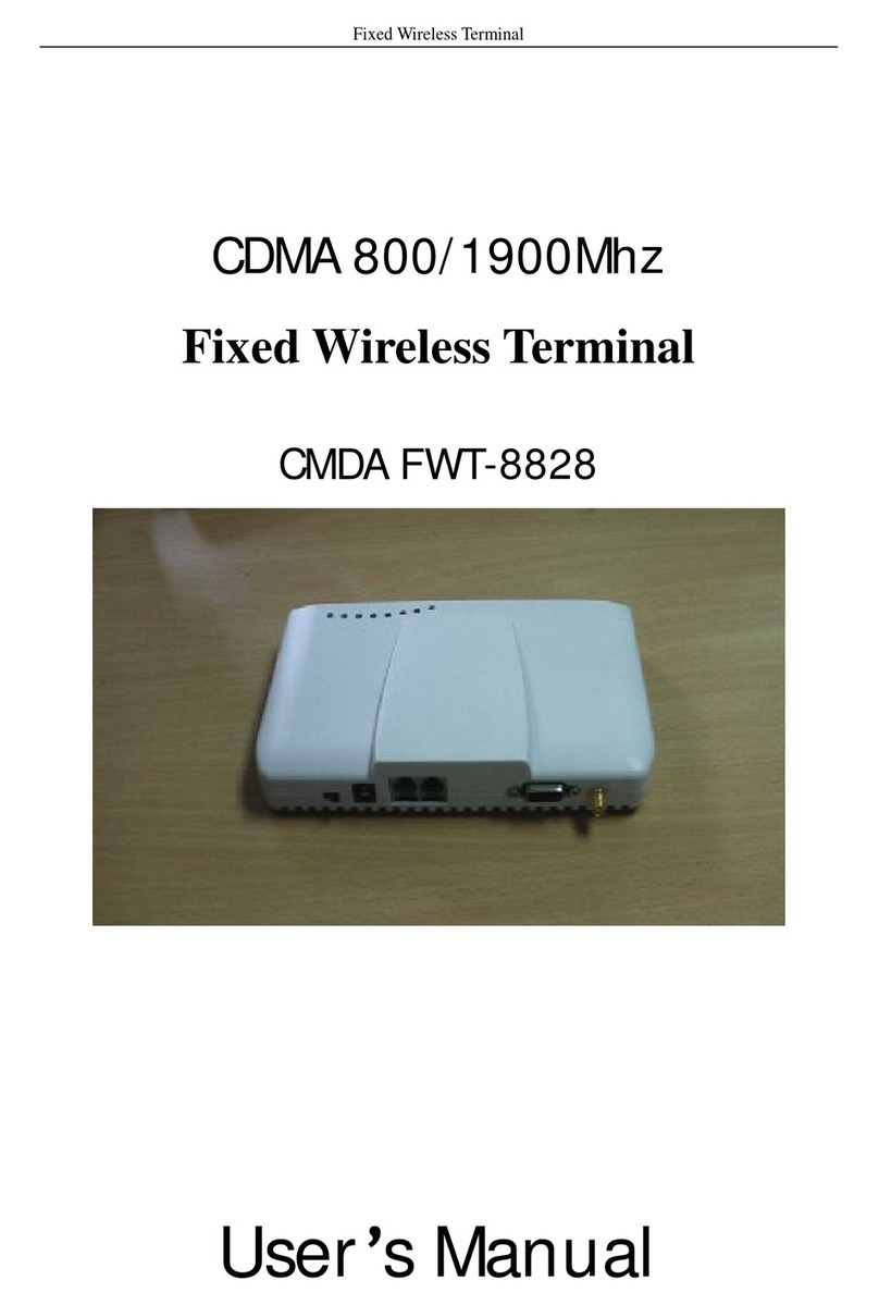
Appostar BS-6500 User manual

http://www.appostar.com
POS PC System Box PC
BS-6500/BS-6520
User’s Manual
Edtion: AUG 2012 Version 1.00

PREFACE
II Box PC BS-6500 / BS-6520
Federal Communications Commission (FCC)
This equipment has been tested and found to comply with the limits for a Class A digital
device, pursuant to part 15 of the FCC Rules. These limits are designed to provide
reasonable protection against harmful interference in a residential installation. This
equipment generates, uses, and can radiate radio frequency energy and, if not installed
and used in accordance with the instructions, may cause harmful interference to radio
communications. However, there is no guarantee that interference will not occur in a
particular installation. If this equipment does cause harmful interference to radio or
television reception, which can be determined by turning the equipment off and on, the
user is encouraged to try to correct the interference by one or more of the following
measures:
‐Reorient or relocate the receiving antenna.
‐Increase the separation between the equipment and receiver.
‐Connect the equipment to an outlet on a circuit different from that to which the
receiver is connected.
‐Consult the dealer or an experienced radio/TV technician for help.
Declaration of Conformity
These devices comply with part 15 of the FCC Rules. Operation is subject to the following
two conditions:
(1) These devices may not cause harmful interference.
(2) These devices must accept any interference received, including interference
that may cause undesired operation.
Lithium Battery Replacement
To avoid possible danger of explosion, ensure the correct polarity when changing the
lithium battery. Replace only with the same or equivalent type recommended by the
manufacturer.
WEEE (Waste from Electrical and Electronic Equipment)
The WEEE wheeled bin symbol on the product or on its packaging indicates that the
product must not be disposed with other waste. Instead, it should be the user’s
responsibility to dispose waste equipment by handing it over to an approved location for
the recycling of electrical waste and electronic equipment. For more information about
where to send your waste equipment for recycling, please contact your local city office,
your household waste disposal service, or the place from where you purchased the
product.
PREFACE
Box PC BS-6500 / BS-6520 III
Disclaimer
The material in this document is for information purposes only and is subject to change
without prior notice. APPOSTAR has made every effort to ensure that this user’s manual
is accurate and complete. However, neither is any liability assumed for errors and
omissions that may have occurred, nor for any damages resulting from the use of this
product and the information contained in this document. APPOSTAR reserves the right to
improve this user’s manual from time to time in the contents hereof without prior notice.
Copyright
This work is protected by copyright laws. Reproduction or retransmission of this
documentation, in whole or in part, without prior written permission of the manufacturer
is a violation of the copyright law.
© 2012 APPOSTAR Technology Co., Ltd. All rights reserved.
Trademark Recognition
Microsoft, MS-DOS and Windows are registered trademarks of Microsoft Corp.
Intel is a trademark or registered trademark of Intel Corporation.
Other software or product names used in this manual are the properties of their
respective owners and are acknowledged.

PREFACE
IV Box PC BS-6500 / BS-6520
SAFETY INSTRUCTIONS
Failure to observe these safety instructions may cause bodily injury, or damage to the
product. Read these instructions carefully and keep this user’s manual in an accessible
location for future reference.
The product may cause a fire or electric shock when it is used
improperly. Observe the above safety measures at all times.
If the product is damaged, immediately turn off the power and
disconnect the power cord. Contact your dealer for assistance.
Do not plug in or unplug the power cord with wet hands.
Do not plug the product into an AC outlet with the incorrect voltage.
(Be sure to use a voltage that is between AC 100V~240V)
Do not plug several products into one multi-outlet.
Do not apply pressure to the power cord or place heavy objects on it.
Immediately stop using the product if it emits strange noise, odor, or smoke.
Do not use aerosol sprayers containing flammable gas inside or around the product.
Do not allow foreign objects or liquids to enter the product, or serious damage may
result.
Do not place the product on an unstable surface. The product may cause a fire if it
is dropped, damaged, or broken.
The following instructions will help you to make better use of this product.
Keep the machine away from locations subject to high humidity, dust, or
temperatures that exceed the specification. (Refer to SEC. 1.3 Specification)
Clean the product only by using a dry cloth or a cloth soaked with detergent. Never
use thinner or other volatile solvents for cleaning.
At the end of the day, clean and inspect the exterior of the machine after the
machine is powered off.
Use only specified accessories.
Do not expose the accessories directly to sunlight, high temperatures, humidity,
dust, or gas.
Do not place heavy objects on top of the product or lean them against the product.
These items may fall down and cause injury.
Do not block the air vent of the product as this can cause heat accumulation inside
the box machine and may cause a fire.

Table Of Contents
CHAPTER 1 ........................................................................2
Product Overview..............................................................2
1.1 Unpacking ..........................................................................................2
1.2 Appearance ........................................................................................3
1.3 Specification .......................................................................................6
1.4 I/O Connection....................................................................................8
CHAPTER 2 ......................................................................13
DRIVER INSTALLATION...................................................13
CHAPTER 3 ......................................................................18
SYSTEM DISASSEMBLY....................................................18
3.1 Remove the Top Cover.......................................................................18
3.2 Replacing the CPU and RAM ................................................................19
3.3 Replacing the HDD.............................................................................20
3.4 Installing the PCI Expansion Card (optional)..........................................21
CHAPTER 4 ......................................................................22
JUMPER SETTINGS ..........................................................22
CHAPTER 5 ......................................................................26
I/O DEFINITION .............................................................26
5.1 Connector Function............................................................................27
5.2 Connector Pin Assignment ..................................................................27
CHAPTER 6 ......................................................................34
TROUBLESHOOTING ........................................................34
APPENDIX .......................................................................35

PRODU
C
2
CHA
P
Pro
d
Intro
d
Thank y
provide
function
require
m
in the s
a
http://
w
1.1 U
Confirm
or dam
a
Q
u
C
T OVERV
I
P
TER
1
d
uct
O
d
uctio
n
ou for ch
o
5 color o
p
. This ser
i
m
ent for r
e
a
me conc
e
w
ww.appo
s
npack
i
that all t
h
a
ged, con
t
u
ick Refere
n
Guide
A
TX
I
EW
1
O
vervi
n
o
osing our
p
tions on
f
i
es delive
r
e
tail busin
e
pt to syn
c
s
tar.com
o
i
n
g
h
e followin
t
act the d
e
n
ce
Power Ad
a
ew
BS-6500
/
f
ront pane
r
s service
a
ess. We a
c
hronize
y
o
r contact
g items a
r
e
aler from
(User’
s
a
pte
r
BS
-
/
BS-6520
w
l combine
a
bility and
lso offer s
y
our retail
your deal
e
r
e contain
e
whom yo
Driver CD
s
Manual in
c
-
6500/BS-6
Main Unit
w
hich are
d with ele
modern
s
everal pe
r
environm
e
r for det
a
e
d in the
c
u purchas
c
luded)
520
Box P
C
based on
gant desi
g
s
tyle to m
e
r
ipherals t
h
ent. Visit
a
iled infor
m
c
arton. If
a
ed the pr
o
Power C
o
P
S
(
C
BS-6500
Intel plat
f
g
n and su
p
e
et your
h
at were
d
our websi
t
m
ation.
a
ny item i
s
o
duct.
o
rd
S
/2 Y-cable
(
optional)
/ BS-6520
f
orm and
p
erior
d
esigned
t
e
s
missing

Box PC
B
1.2
A
1.2.1
Dimens
B
S-6500 /
B
A
ppear
a
Dime
n
ion (W x
D
B
S-6520
a
nce
n
sion
D
x H): 3
0
0
6 mm x
2
Wi
d
2
88 mm x
d
th=306 m
70 mm (
1
m
D
e
PR
O
1
2.1” x 11
e
pth=288
m
Height=
O
DUCT O
V
.3” x 2.8”
)
m
m
70 mm
V
ERVIEW
3
)

PRODUCT OVERVIEW
4 Box PC BS-6500 / BS-6520
1.2.2 Front View
ICON NAME DISCRIPTION
Power Button Press the Power Button to turn ON/OFF the POS system.
The Power LED Indicator will display the current power
status of the POS system.
Reset Button Press the Reset Button will restart your system.
Power LED
Indicator
Indicates the power ON/OFF status.
Orange – When the power cord is connected and the
power switch at the adapter is turned on, the light turns
orange and the 5V standby is ready for Wake On LAN
function if preset.
Green – Once the system is powered on, the light turns
from orange into green and remains green. When the POS
system goes into standby mode, the light signal will turn
to orange.
HDD LED
Indicator
Indicates the operational status of the Hard Disk Drive
(HDD). The Red LED Indicator will be lit when HDD is
being accessed.
LAN LED
Indicator
When the LAN link is established, the Green LAN LED
Indicator will be lit. While the server is communicating via
LAN, the Green LAN LED Indicator will be blinking.
Dual USB Port
The USB 2.0 port is a hardware interface for high-speed
peripherals and also supports USB 1.1 compliant devices.
Devices can be plugged / unplugged without the need to
turn off the PC.

Box PC
B
1.2.3
NOTE:
1.2.4
Co
r
The
Do
n
of t
h
Pro
v
to
k
(R
e
Kee
COM5 +
U
C
O
A
TX P
o
DC outp
u
B
S-6500 /
B
Rear
V
For mor
e
SEC. 1.
4
Side V
r
rect A
i
air vents
a
n
ot block
t
h
e proces
s
v
ide a fre
e
k
eep a go
o
e
fer to Fi
g
p the pro
d
COM2
U
SB x 2
O
M1
o
we
r
VG
A
D
ut
B
S-6520
V
iew
e
detailed
4
I/O Co
n
iew
i
rflow
a
re locate
d
t
he air ve
n
s
or.
e
area of
m
o
d airflow,
g
ure 1-A
)
d
uct away
PS/2
D
IO Cash Dr
a
informati
o
n
nection
a
d
on both
s
n
ts; keep
t
m
ore than
especiall
y
)
from any
a
we
r
Fi
g
o
n on the
a
nd CH.
6
s
ides of th
t
hem clea
n
5 cm for t
y
near hot
kind of h
e
g
ure 1-A
above I/
O
6
I/O De
f
e product
n
and dust
he produ
c
places lik
e
at sourc
e
A
udi
PR
O
O
illustrati
o
f
inition.
for a bett
e
-free to p
r
c
t by remo
e cooling
f
e
s.
LAN + USB
x
Par
a
COM
3
o-out
O
DUCT O
V
o
n, please
e
r cooling
r
event ov
e
ving any
o
f
ans.
x 2
a
llel Port (LP
PCI Metal
US
B
COM 4
3
V
ERVIEW
5
refer to
purpose.
e
rheating
o
bstacles
T1)
Cover
B
x 2

PRODUCT OVERVIEW
6 Box PC BS-6500 / BS-6520
1.3 Specification
Model Name BS-6500 BS-6520
System
Mainboard IFP2-945GC
CPU Intel Celeron 440 2.0GHz
Intel Pentium E2160 dual
core 1.8GHz
Chipset Intel 82945GC+ICH7
Main Memory 512MB DDRII, up to 2GB
HDD 2.5” SATA HDD 160G
Expansion 1 x PCI slot, 1 x Compact Flash II slot
Network 10/100M/1G bps onboard Ethernet controller
Front I/O
USB Port 2 x USB 2.0 A Type
Rear I/O
Serial Port 5 x External: COM1, COM2, COM3, COM4 (DB9),
COM5 (RJ45), all with 5V/12V selectable
Cash Drawer Port 1 x RJ11 with DC 12V (single/dual)
Keyboard / Mouse Port 1 x PS/2
VGA Port 1 x VGA (DB15)
Audio Jack 1 x Line-out
Ethernet Port 1 x RJ45 10/100 M Base-T
Parallel Port 1 x Bi-directional Parallel
USB Port 6 x USB 2.0 A Type
DC Jack 1 x DC 12V/ 2.5A output
Special Features
Optional ODD CDRW/DVDROM 8x24 SATA COMBO
Control / Indicator
Power Button 1
Reset Button 1
LED Indicators 3 (HDD / Power / LAN)
Powering
Power Supply AC 100V~240V/270W ATX power adapter

PRODUCT OVERVIEW
Box PC BS-6500 / BS-6520 7
Environment
EMC & Safety CE/FCC Class A
Operating Temperature 0°C ~ 40°C
Storage Temperature -20°C ~ 60°C
Operating Humidity 15% - 80% RH
Storage Humidity 20% - 90% RH
Mechanical
Housing Color Cool White, Dark Gray
Construction ABS + SECC
Dimension (W x D x H) 306 x 288 x 70 mm
Weight N.W. 3.2 kg
OS Compatibility Windows 7, Windows XP/XPE, POS Ready, Linux

PRODU
C
8
1.4 I
/
1.4.1
No.
NOTE:
C
T OVERV
/
O Co
n
I/O C
o
C
o
COM 1/
2
COM 5
+
LAN +
U
Printer
(
PCI Met
a
POWER
POWER
VGA
Keyboa
r
Cash Dr
a
Audio-o
u
USB Po
r
To
a
cov
e
To
a
pro
t
IEW
n
necti
o
o
nnect
o
o
nnector
2
/3/4
+
USB
U
SB
(
LPT1)
a
l Cover
(DC out
p
(DC Inp
u
r
d/Mous
e
a
wer (DI
u
t
r
t
a
void conf
e
r, remov
e
a
void conf
t
ected wit
o
n
o
rs
S
S
U
R
U
P
I
n
m
P
p
ut)
D
u
t)
A
D
e
P
O)
D
L
U
usion wit
h
e
the cov
e
usion wit
h
h cover, r
e
S
erial port
S
erial port
U
SB 2.0 A-
R
J45 LAN
C
U
SB 2.0 A-
arallel po
r
n
stall PCI
m
etal cove
P
CI Expa
n
D
C 12V/2.
5
A
TX Power
D
B15 VGA
S/2 Conn
e
D
igital I/O
ine-out w
i
U
SB 2.0 A-
h
LAN por
t
e
r before
u
h
DC jack/
e
move th
e
D
e
with DB9
with RJ4
5
type Con
n
C
onnector
type Con
n
r
t with DB
2
Expansio
n
r (Refer
t
n
sion Car
d
5
A output
Connecto
Connecto
r
e
ctor
with RJ11
i
th audio
J
type Con
n
t
, the CO
M
u
se.
input, the
e
cover be
f
Box P
e
scriptio
n
Connecto
5
Connect
o
n
ector x 2
x 1
n
ector x 2
2
5 Conne
c
n
Card by
t
o SEC. 3
.
d
.)
(See No
t
r
r
Connect
o
J
ack
n
ector x 2
M
5 port is
p
DC 12V j
a
f
ore use.
C BS-6500
n
r
o
r x 1 (Se
c
tor x 1
removing
.
4 Instal
l
t
e)
o
r 12V (si
n
p
rotected
a
ck/outpu
/ BS-6520
e Note)
the PCI
l
ing the
n
gle/dual)
with
t is

PRODUCT OVERVIEW
Box PC BS-6500 / BS-6520 9
1.4.2 Peripheral Installation
a. Connecting a PS/2 Keyboard or Mouse
Connect an external PS/2 type mouse or keyboard to this port.
NOTE: If you would like to use mouse and keyboard simultaneously, use the PS/2
Y-cable supplied in the Accessory Kit. (See SEC. 1.1 Unpacking)
b. Connecting a Printer
Connect one end of the parallel cable to the DB25 parallel port (LPT 1) at the
BS-6500/BS-6520, and the other end to the printer. Turn on both the printer and the
BS-6500/BS-6520.

PRODUCT OVERVIEW
10 Box PC BS-6500 / BS-6520
c. Connecting a Cash Drawer
Connect one end of the phone line cable to the RJ11 cash drawer port at the
BS-6500/BS-6520, and the other end to the cash drawer.
NOTE: Check the power specification of your cash drawer first, and correct the
jumper setting if necessary.
d. Connecting a Display Touch Panel
Connect the male end of the VGA cable to the DB15 VGA female port at the
BS-6500/BS-6520, and the other end to the display touch panel.

Box PC
B
e. Con
n
This po
r
RJ45 p
o
f. Con
n
Connec
t
BS-650
0
printer
e
NOTE:
Jumpe
r
B
S-6500 /
B
n
ecting t
o
r
t support
s
o
rt at the
B
n
ecting S
e
t
the fem
a
0
/BS-652
0
e
tc.) Turn
If the po
w
r
Setting
s
B
S-6520
o
a LAN
s
LAN (net
w
B
S-6500/
B
e
rial Dev
i
a
le end of
0
; and th
e
on both t
w
er of you
r
s
for the
p
w
ork) fun
c
B
S-6520,
a
i
ce
the serial
e
other en
d
he device
r
device is
p
roper po
w
c
tions. Co
n
a
nd the o
t
cable to t
d
to the s
e
and the
B
supplied
b
w
er sourc
e
n
nect one
t
her end t
o
he male s
e
rial devi
c
B
S-6500/
B
b
y a serial
e
setting.
PR
O
end of th
e
o
the Inte
erial port
c
e (ex. cu
s
B
S-6520.
COM por
t
O
DUCT O
V
e
LAN cabl
e
rnet devi
c
at the
s
tomer di
s
t
,refer t
o
V
ERVIEW
11
e
to the
c
e.
s
play,
o
CH. 4

PRODUCT OVERVIEW
12 Box PC BS-6500 / BS-6520
g. Connecting an Audio-out Device
An audio device (headphone or speakers) can be connected through this jack.
h. Connecting USB Device
Connect USB A-Type connector of USB cable to the BS-6500/BS-6520, and USB
B-Type connector of USB cable to the USB device.

DRIVER INSTALLATION
Box PC BS-6500 / BS-6520 13
CHAPTER 2
DRIVER INSTALLATION
This chapter describes the driver requirements and how to install the drivers from the
driver CD. All step-by-step procedures described below are for Windows XP and
similar on all other Microsoft Windows platforms.
Insert the driver CD into your CD-ROM drive. Windows will automatically detect it and
the Appostar Driver Installer appears on the screen. If not, locate the Setup.exe
file at CD:\ and double-click it to execute the Appostar Driver Installer. Follow the
on-screen instructions to complete the installation.
Motherboard Driver Installation
a. Click Install Motherboard Drivers.
b. Select your model name and click
Next to continue.
c. Install the overall drivers
accordingly. After installation you will
be prompted to restart your system.

DRIVER INSTALLATION
14 Box PC BS-6500 / BS-6520
2.1 Chipset Driver Installation
1. Click Install Chipset Driver.
2. Follow the on-screen instructions to complete the installation.
d. Click Next on the Welcome screen to
continue.
e. Click Yes on the License Agreement
screen to continue
f. Click Next on the Readme File
Information screen to continue.
g. Click Finish to complete the
installation.

DRIVER INSTALLATION
Box PC BS-6500 / BS-6520 15
2.2 Graphics Driver Installation
1. Click Install Graphics Driver.
2. Follow the following instructions to complete the installation.
a. Select English as setup language and
click Next to continue.
b. Click Next to continue.
c. Click Install to begin the installation.
d. A progress window appears.
e. Click Continue Anyway to continue. f. Click Finish to complete the
installation.

DRIVER INSTALLATION
16 Box PC BS-6500 / BS-6520
2.3 LAN Driver Installation
1. Click Install Ethernet Driver.
2. Follow the on-screen instructions to complete the installation.
a. A Preparing Setup window appears.
Please wait.
b. Click Next on the Welcome screen to
continue.
c. Click Install to begin the
installation. A progress window pops
up. Please wait.
d. Click Finish to complete the
installation.
This manual suits for next models
1
Table of contents
Other Appostar Touch Terminal manuals

Appostar
Appostar KP-5660 User manual

Appostar
Appostar KP-5362 User manual

Appostar
Appostar KP-5360 User manual

Appostar
Appostar NP-3262 User manual

Appostar
Appostar SP-7260 User manual

Appostar
Appostar KP-5370 User manual

Appostar
Appostar FP-4266 User manual

Appostar
Appostar KP-5374 User manual

Appostar
Appostar KP-5562 User manual

Appostar
Appostar KP-5374 User manual