manuals.online logo
Brands
  1. Home
  2. •
  3. Brands
  4. •
  5. Aqua One
  6. •
  7. Indoor Furnishing
  8. •
  9. Aqua One Shades 1+1 Cabinet User manual

Aqua One Shades 1+1 Cabinet User manual

Assembly Instructions
Please keep for future reference
Important - Please read these instructions fully before starting assembly
Shades 1+1 Cabinet
Version 1 : 07/12/2018
ALR3507
Safety and Care Advice
Important - Please read these instructions fully before starting assembly
• Make sure you have enough
space to layout the parts before
starting.
• Assemble the item as close to
its final position (in the same
room) as possible.
• Assemble on a soft level
surface to avoid damaging the
unit or your floor (use opened
out unit carton).
Care and maintenance
Contact Us
• Only clean using a damp cloth
and mild detergent, do no use
bleach or abrasive cleaners.
Aqua Pacific UK Ltd.
Unit 10, Oriana Way
Nursling Industrial Estate
Southampton
SO16 0YU
Tel +44 (0) 2380 734000
Fax +44 (0) 2380 740200
[email protected]
• From time to time check that
there are no loose screws on
this unit.
• This product should not be
discarded with household
waste. Take to your local
authority waste disposal centre.
• Warning: This unit is heavy.
Please lift with care.
• Check you have all the
components and tools listed.
• Remove all fittings from the
plastic bags and separate them
into their groups.
• Keep children and animals
away from the work area, small
parts could choke if swallowed.
• Parts of the assembly will be
easier with 2 people.
Tools
Rule Scissors Hammer
Eye protection
(when using a
hammer or drill)
Cross-head
screwdriver
Electric drill
(do not use for
fitting screws)
Spirit
level
• We do not
recommend the
use of power
drill/drivers for
inserting screws,
as this could damage the unit.
Only use hand screwdrivers.
• Safety note: This unit must
be secured to a wall using the
overbalance protector kits
supplied.
• Dispose of all packaging
carefully and responsibly.
Panels
Please check you have all the panels listed below
1Drawer Front
(DF-00015635)
(36.2 x 15.7cm)
4Drawer Back
(W326-124)
(32.6 x 12.4cm)
5Drawer Base
(T337-297)
(33.7 x 29.7cm)
2Left Drawer
Side (W300-124LH)
(30 x 12.4cm)
3Right Drawer
Side (W300-124RH)
(30 x 12.4cm)
6Left Side
(DF-00014969)
(69.6 x 27.9cm)
7Right Side
(DF-00014970)
(69.6 x 27.9cm)
8Rail (DF-00015638)
(36.8 x 6cm)
9Support Rail (DF-00015641)
(36.8 x 6cm)
10 Top (DF-00015636)
(51.6 x 41cm)
12 Back (DF-00015639)
(75.5 x 24.4cm)
13 Door (DF-00014967)
(45.4 x 36.2cm)
14 Left Leg
(DF-00014966)
(75.5 x 4.5cm x 4.5cm)
x 2
15 Right Leg
(DF-00014978)
(75.5 x 4.5cm x 4.5cm)
x 2
11 Base (DF-00015637)
(36.8 x 33cm)
Fittings
Please check you have all the fittings listed below
Bag 1
A B
Large Metal Dowel (F901) x 26
C
D E
Large Locking Cam
Nut (F900) x 26
Bag 2
H
Individual Bags
Q
G
45mm Screw (F65) x 2
F
Wooden Dowel (F22) x 26
O
9mm Screw (F73) x 4
P
Pre-mounted
hinge (F419) x 2
R
Overbalance protector
kit (F474) x 2
Handle (FHK9) x 1
DO NOT USE the Screws supplied with the Handles
Handle (FHK7) x 1
Shelf stud (F110) x 6
These are for fixing the Hood.
See separate instructions for fitting details.
*
Door Stop (F464) x 1
13mm Screw (F79) x 2 Bracket (F945) x 1
I
A
Large Metal Dowel (F901) x 2
J
Small Locking Cam
Nut (F900) x 2
K
Knock-in Peg (F171GY) x 4
9mm Screw (F74) x 2
ML N
Wedgefix (F639) x 2
19mm Screw (F461) x 3
S
Drawer runner (F1004) x 2
1
Step 1
Step 2
Step 3
Prepare the Drawer
Sides
Insert a Small Locking
Cam Nut into the Left
Drawer Side and the
Right Drawer Side.
Note: The arrow on the
Small Locking Cam Nut
must point towards the
hole in the edge of the
panel.
Attach the Drawer
Sides to the Drawer
Front
Push theDrawer Side
onto the back of the
Drawer Front.
Turn the Small Locking
Cam nuts on the Drawer
Side.
Note: Turn the Small
Locking Cam nuts
clockwise to secure the
panels - more than 1/2 a
turn.
A
J
J
JJ
Prepare the Drawer
Front
Screw 2 Metal Dowels
into the Drawer Front.
Note: Tighten the Metal
Dowels up fully against
the panel.
23
2
3
A
A
1
Use Bag 2 for steps 1 - 7
1
Step 4
Step 5
Step 8
Fit the Drawer Base
Slide the Drawer Base
down the grooves in the
Drawer Sides and down
into the groove in the
Drawer Front.
Fit the Drawer Back
Fit the Drawer Back
between the Drawer
Sides.
Make sure that the
Drawer Base fits into the
groove in the Drawer
Back.
Hold the Drawer Back
in position and tap the
Knock-in Pegs through
the holes in the Drawer
Sides.
Step 6
Attach the Handle
Attach the Handle to the
Drawer Front using two
19mm Screws.
Step 8
Step 7
Fit the Wedgefixes
Turn the drawer
assembly over and slide
2 Wedgefixes into the
front and back grooves,
as shown, and tighten up
the screws.
K
K
K
K
N
N
N
2
3
2
4
5
3
The Drawer assembly
must be square before
fitting the wedgefixes
5
L
L
P
1
DO NOT USE the Screws supplied with the Handle
C
C
C
C
Step 8
C
C
10mm
C
6
B
B
B
B
B
B
B
B
B
6
Prepare the Left Side
a: Tap 6 Dowels into the
Left Side.
Note: Wooden Dowels
must not stick out from
the edge by more than
10mm or they may
damage other panels.
b: Insert 8 Large Locking
Cam Nuts into the Left
Side.
Note: The arrow on the
Large Locking Cam Nut
must point towards the
hole in the edge of the
panel.
c: Screw 3 Metal Dowels
into the Left Side.
a:
b:
c:
6
A
AA
C
C
A
A
A
A
A
A
A
14
15
Step 8
Step 9
Prepare a Left Leg
Screw 4 Metal Dowels
into 1 of the Left Legs
and tap in a Wooden
Dowel.
Step 8Step 10
Prepare a Right Leg
Screw 3 Metal Dowels
into 1 of the Right Legs
and tap in a Wooden
Dowel.
Use Bag 1 for steps 8 - end
6
Step 11
Step 8
Step 12
Fit the Legs to the Left
Side
a: Push the 2 Legs onto
the Left Side.
b: Use a screwdriver to
tighten the 6 Large
Locking Cam Nuts
fitted to the Left Side.
Note: Turn the Locking
Cam Nuts as far as they
will go - more than 1/2 a
turn.
6
14
6
a:
b:
a:
b:
F
F
S
S
F
Fit a Runner to the Left
Side
a: Place a Runner on
the Left Side, as shown.
Slide back the top of
Runner and use the 2nd
hole from the front to fit
the 1st 9mm Screw.
b: Slide the Runner
back the other way and
fit the 2nd 9mm Screw
into the corresponding
hole in the Left Side.
6
15
C
C
C
C
Step 13
C
C
10mm
C
7
B
Prepare the Right Side
a: Tap 6 Dowels into the
Right Side.
Note: Wooden Dowels
must not stick out from
the edge by more than
10mm or they may
damage other panels.
b: Insert 8 Large Locking
Cam Nuts into the Right
Side.
Note: The arrow on the
Large Locking Cam Nut
must point towards the
hole in the edge of the
panel.
c: Screw 3 Metal Dowels
into the Right Side.
a:
b:
c:
7
A
AA
C
C
A
A
A
A
A
A
A
14
15
Step 8
Step 14
Prepare a Left Leg
Screw 3 Metal Dowels
into 1 of the Left Legs
and tap in a Wooden
Dowel.
Step 8
Step 15
Prepare a Right Leg
Screw 4 Metal Dowels
into 1 of the Right Legs
and tap in a Wooden
Dowel.
B
B
B
B
B
7
B
B
B
7
7
Step 16
Step 8
Step 17
Fit the Legs to the Right
Side
a: Push the 2 Legs onto
the Right Side.
b: Use a screwdriver to
tighten the 6 Large
Locking Cam Nuts
fitted to the Right Side.
Note: Turn the Locking
Cam Nuts as far as they
will go - more than 1/2 a
turn.
14
a:
b:
a:
b:
Fit a Runner to the
Right Side
a: Place a Runner on
the Right Side, as
shown. Slide back the
top of Runner and use
the 2nd hole from the
front to fit the 1st 9mm
Screw.
b: Slide the Runner
back the other way and
fit the 2nd 9mm Screw
into the corresponding
hole in the Right Side.
2
F
7
27
F
S
F
S
15
C
C
C
8
Finished
Front Edge
Finished
Front Edge
Prepare the Rail
a: Fit the Bracket to the
mark-hole in the Rail
using a 13mm Screw.
b: 4APÖÖ7OODENÖ
$OWELSÖINTOÖTHEÖRail
Insert 2 ,ARGE Locking
Cam Nuts into the Rail.
Step 8
Step 19
Prepare the Base
4APÖÖ7OODENÖ$OWELSÖ
INTOÖTHEÖ"ASE
Insert 4 ,ARGE Locking
Cam Nuts into the Base.
Step 8
Step 20
8
Fit the Rail to the Right
Side
Push the Rail onto the
Right Side.
Use a screwdriver to
tighten the Large Locking
Cam Nuts fitted to the
Rail.
7
8
Step 18
H
a: G
H
G
C
B
B
b:
C
C
B
B
B
B
Finished
Front Edge
11
Finished
Front Edge
Step 21
Fit the Base to the
Right Side
Push the Base onto the
Right Side.
Use a screwdriver to
tighten the 2 Large
Locking Cam Nuts
fitted to the Base.
Secure the Bracket on
the Rail to the mark-hole
in the Base using a
13mm Screw.
Fit the Support Rail
Push the 3UPPORTÖ2AIL
onto the Right Side.
Use a screwdriver to
tighten the Large Locking
Cam Nut fitted to the
3UPPORTÖ2AIL.
Step 8
Step 22
C
C
B
B
Prepare the Support
Rail
4APÖÖ7OODENÖ$OWELSÖ
INTOÖTHEÖ3UPPORTÖ2AIL
Insert 2 ,ARGE Locking
Cam Nuts into the
SUPPORTÖRail.
9
Step 8
Step 23
Support the
Support Rail until
the Left Side has
been fitted
G
7
G
11
7
9
Step 24
Fit the Left Side
Push the Left Side onto
the assembly.
Use a screwdriver to
tighten the 4 Large
Locking Cam Nuts
fitted to the Base, Rail
and Support Rail.
Step 8
Step 25
6
Prepare the Top
a: Fit the 2 Brackets
from the Overbalance
Protector Kits to the
shallow mark-holes
drilled into the Top
using 1 of their Screws.
Note: Only fit 1 of the
Screws, the other 1 will
be fitted later.
b: Screw 6 Metal
Dowels into the Top.
a:
b:
10
Finished
Front Edge
R
R
R
A
A
10
A
A
A
A
Finished
Front Edge
Raise the Sides
using packaging,
wood, books etc.
Step 26
Fit the Top
To make the fitting of the
Top easier, raise the
assembly as shown.
Push the Top onto the
assembly.
Use a screwdriver to
tighten the 4 Locking
Cam Nuts fitted to the
Sides.
10
CC
Step 28
Prepare the Back
4APÖÖ7OODENÖ$OWELSÖÖ
INTOÖTHEÖ"ACK
Insert 2 Large Locking
Cam Nuts into the Back.
Fit the Back
Push the Back up onto
the Top.
Use a screwdriver to
tighten the 2 Large
Locking Cam Nuts fitted
to the Back.
Fix the Back to the back
edge of the Base with
two 45mm Screws.
B
B
12
Step 27
D
D
12
Step 29
a:
b: RR
Top
This unit must be fixed to a wall using the
2 Overbalance Protector Kits provided
Secure the unit to a
wall
a: Before fitting the unit
to a wall, use a Spirit
Level to check the Top of
the unit is level,
front-to-back and
side-to-side in the 3
positions shown.
Use suitable packing
pieces (not supplied) to
make the unit level.
To prevent possible
overbalancing this unit
must be secured to a
suitable wall by fitting the
2 Overbalance Protector
Kits to a wall.
b: Push the unit up
against the wall and slide
the Brackets against the
wall. Fit the 2nd Screw
from the kits into the
underside of the Top
panel.
Mark the slot at the back
of the Brackets for drilling
into the wall.
Wall fixings are not
supplied as they will need
to suit the wall type.
Take care when drilling
the wall that you do not
drill into any pipes, wires
etc. If in doubt, consult an
expert.
R
R
Step 30
Fit the Drawer
Slide both the Runners
forward and locate the
Drawer Sides between
them, lining up their
holes with the 2nd
'threaded' holes in the
Runners.
Working from the inside
of the Drawer, insert 2
9mm Screws through the
Drawer Sides and out
into the 2nd threaded
hole in the Runner.
Note: Do not overtighten
the Screws. If they catch
on the Runners you may
need to loosen them
slightly.
2nd threaded
hole
S
M
The Runners could
have sharp edges and
we recommend that
you position them
using a Screwdriver.
Prepare the Door
Push fit 2 Hinges into the
Door and secure them by
tightening up their 2
screws.
Step 31
Q
Q13
Step 32
Fit the Door
NOTE: The Door can be
fitted to either side.
Line up the 2 screws in
the top Hinge with the 2
holes at the top of the
Sides and push them in.
Now push in the other
Hinge.
When both of the Hinges
have been pushed into
place, tighten their 2
screws.
Press the Screws into
the holes in the panels
When the Hinges have
been pushed in,
tighten up their Screws
Note: Fit the
top hinge 1st
Note: Fit the
top hinge 1st
13
13
OROR
O
Step 33
Fit the Handle
Attach a Handle to the
Door using a 19mm
Screw.
DO NOT USE the Screw supplied with the Handle
L
OROR
L
O
Step 34
Adjust the Door if
needed
a: Height adjustment.
Loosen Screws A on
Hinge Plates and move
Door up or down as
required.
Retighten Screw A.
b: Forward and Back
adjustment.
Loosen Screw B on
Hinge Plate and move
Door in or out as
required.
Retighten Screw B.
c: Sideways
adjustment.
To move Door ‘out’
loosen Screw C.
To move Door ‘in’ tighten
Screw C.
b:
a:
A
A
B
c:
C
Step 35
Fit the Door Stop
Screw the Door Stop into
the Leg, as shown.
The position of the Door
can be adjusted by
turning the Door Stop
clockwise or
anti-clockwise.
Assembly is complete
OROR
E
E

Other Aqua One Indoor Furnishing manuals

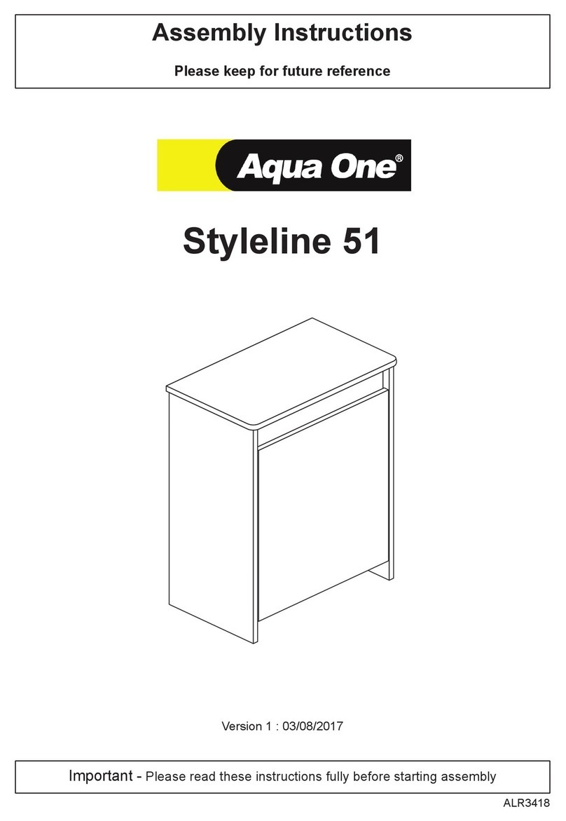
Aqua One Styleline 51 User manual

Aqua One

Aqua One Styleline 51 User manual

Aqua One Inspire 40 User manual

Aqua One

Aqua One Inspire 40 User manual

Aqua One OakStyle Urban 230 User manual

Aqua One

Aqua One OakStyle Urban 230 User manual

Aqua One Cabinet 53445 User manual

Aqua One

Aqua One Cabinet 53445 User manual

Aqua One Styleline 93 User manual

Aqua One

Aqua One Styleline 93 User manual

Aqua One Oakstyle 145 User manual

Aqua One

Aqua One Oakstyle 145 User manual

Aqua One Aqua Nano Bow 80 User manual

Aqua One

Aqua One Aqua Nano Bow 80 User manual

Aqua One Aqua Nano Bow 60 User manual

Aqua One

Aqua One Aqua Nano Bow 60 User manual

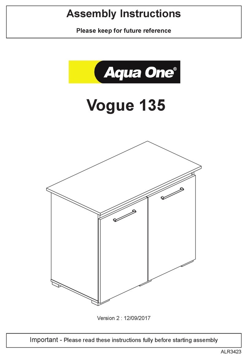
Aqua One Vogue 135 User manual

Aqua One

Aqua One Vogue 135 User manual

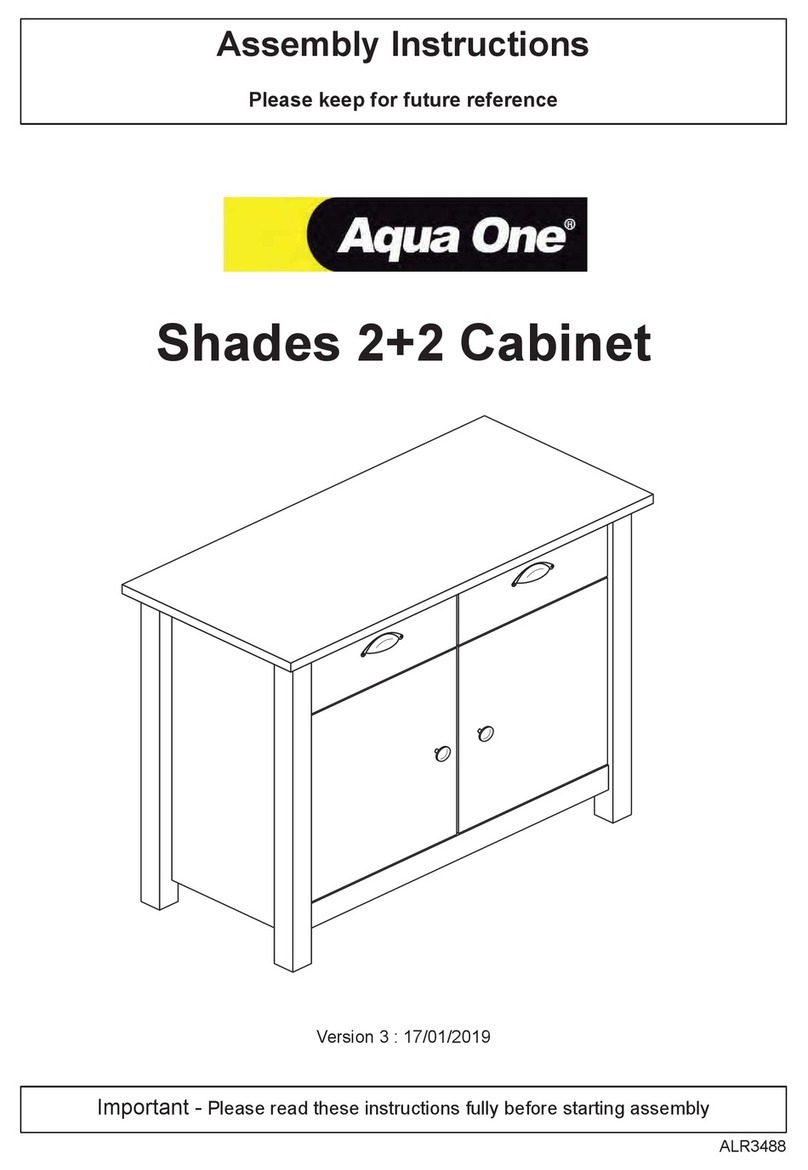
Aqua One Shades 2+2 Cabinet User manual

Aqua One

Aqua One Shades 2+2 Cabinet User manual

Aqua One AquaOne Vogue 245 User manual
Aqua One

Aqua One AquaOne Vogue 245 User manual

Aqua One Cabinet 53443 User manual

Aqua One

Aqua One Cabinet 53443 User manual

Aqua One Oakstyle 300 User manual

Aqua One

Aqua One Oakstyle 300 User manual

Aqua One Oakstyle 110 User manual

Aqua One

Aqua One Oakstyle 110 User manual
Aqua One Inspire 60 Mk2 User manual

Aqua One

Aqua One Inspire 60 Mk2 User manual

Aqua One Cabinet 53446 User manual

Aqua One

Aqua One Cabinet 53446 User manual

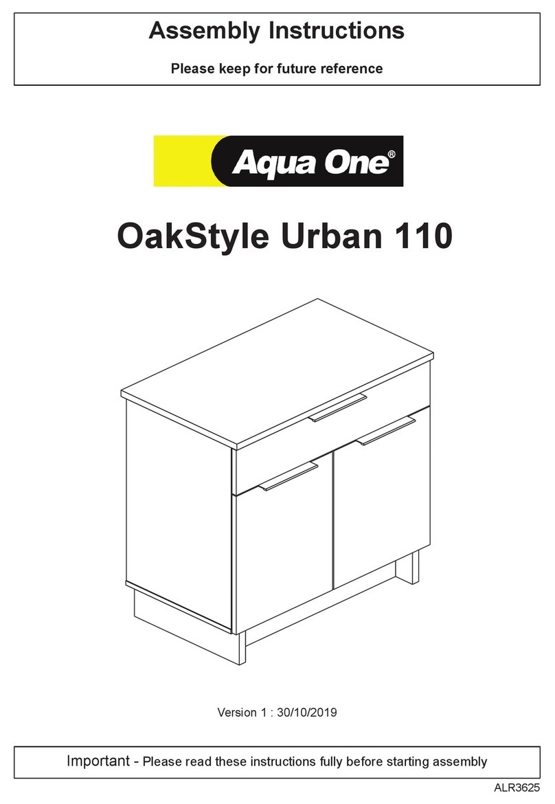
Aqua One OakStyle Urban 110 User manual

Aqua One

Aqua One OakStyle Urban 110 User manual

Aqua One Oakstyle Chic 3+2 Unit User manual
Aqua One

Aqua One Oakstyle Chic 3+2 Unit User manual

Aqua One Styleline 60 User manual

Aqua One

Aqua One Styleline 60 User manual
Popular Indoor Furnishing manuals by other brands

Schildmeyer 566154 Assembly instructions

Schildmeyer

Schildmeyer 566154 Assembly instructions

Furniture Solutions 17ONY02B instruction manual

Furniture Solutions

Furniture Solutions 17ONY02B instruction manual

Furniture of America CM3492PT Assembly instructions

Furniture of America

Furniture of America CM3492PT Assembly instructions

ofichairs Oxford patin quick start guide

ofichairs

ofichairs Oxford patin quick start guide

modway MOD-6316 quick start guide

modway

modway MOD-6316 quick start guide

SEI CHELMSFORD Assembly instructions

SEI

SEI CHELMSFORD Assembly instructions

Dj MOVEIS Rack Verano manual

Dj MOVEIS

Dj MOVEIS Rack Verano manual

Courtyard Creations TGS17FS-WM Assembly instructions

Courtyard Creations

Courtyard Creations TGS17FS-WM Assembly instructions

Fanani IGLOO TECHST-GL Assembly instructions

Fanani

Fanani IGLOO TECHST-GL Assembly instructions

Assa Abloy Traka Touch Series user guide

Assa Abloy

Assa Abloy Traka Touch Series user guide

The Human Solution Neutral Posture Assembly guide

The Human Solution

The Human Solution Neutral Posture Assembly guide

Jysk Jleisure 4705120 Assembly instructions

Jysk

Jysk Jleisure 4705120 Assembly instructions

NorSap 800 Sailor user manual

NorSap

NorSap 800 Sailor user manual

LIBRARY PEOPLE Lingo Square with castors Assembly guide

LIBRARY PEOPLE

LIBRARY PEOPLE Lingo Square with castors Assembly guide

ACG Jennifer Taylor S52180 Assembly instruction

ACG

ACG Jennifer Taylor S52180 Assembly instruction

IKEA MARKUS manual

IKEA

IKEA MARKUS manual

DURAVIT L-Cube LC 7382 Mounting instructions

DURAVIT

DURAVIT L-Cube LC 7382 Mounting instructions

Uplift Desk PDC005 manual

Uplift Desk

Uplift Desk PDC005 manual

manuals.online logo
manuals.online logoBrands
  • About & Mission
  • Contact us
  • Privacy Policy
  • Terms and Conditions

Copyright 2025 Manuals.Online. All Rights Reserved.