manuals.online logo
Brands
  1. Home
  2. •
  3. Brands
  4. •
  5. AQUAPHOR
  6. •
  7. Water Filtration System
  8. •
  9. AQUAPHOR APRO Series User manual

AQUAPHOR APRO Series User manual

AQUAPHOR
PROFESSIONAL
WATER TREATMENT
L.Tolstoi 2A, Sillamäe,
40231 Estonia
www.pro.aquaphor.com
International: +372 356 2204 21
Skype: aquaphor market.pro
e-mail: market.pro@aquaphor.com
REVERSE OSMOSIS SYSTEM
APRO series
Installation and operation manual
Model:
Serial number:
Installation site:
AQUAPHOR
PROFESSIONAL
WATER TREATMENT
L.Tolstoi 2A, Sillamäe,
40231 Estonia
www.pro.aquaphor.com
International: +372 356 2204 21
Skype: aquaphor market.pro
e-mail: market.pro@aquaphor.com
Table of contents
1. INTRODUCTION
2. ASSIGNMENT
3. DESIGNATION AND ARRANGEDSETS
3.1 Designation
3.2 Completeness
4. SPECIFICATION
5. REQUIREMENTS FOR THEQUALITY
6. EQUIPMENT AND PRINCIPE OFWORK
6.1 Equipment
6.2 Technological drawing reverse osmosis systemAquaphor
7. INSTALLATION REVERSE OSMOSIS SYSTEM
7.1 Attention
7.2 Connection
7.3 Start-up
7.4 Security measures
7.5 Commissioning
7.6 Operation
7.7 Maintenance operations atshutdown
7.8 Mode
8. Control system
8.1 Control and display system
8.2 Operating controller
8.3 technical parameters of the controller
8.4 Display panel controller
8.5 Connecting and configuring thecontroller
8.6 Electrical drawings
8.7 Correspondence table symbols in Russian and Englishlanguages.
8.8 Troubleshooting
9. FLUSHING MODE ON PLACE (CIP)
10. RULES OF STORAGE ANDTRANSPORTATION
11. WARRANTY
12. CE CERTIFICATE
13. EC DECLARATION OF CONFORMITY
AQUAPHOR
PROFESSIONAL
WATER TREATMENT
L.Tolstoi 2A, Sillamäe,
40231 Estonia
www.pro.aquaphor.com
International: +372 356 2204 21
Skype: aquaphor market.pro
e-mail: market.pro@aquaphor.com
1. INTRODUCTION
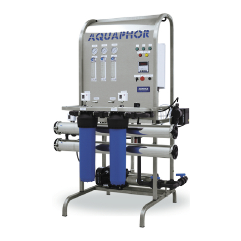
The reverse osmosis system of Aquaphor (hereinafter RO system) manufactured by
“Westaqua-Invest OÜ“(Estonia) on request “Aquaphor” (Russia, Saint-Petersburg).
The RO system is designed to reduce the total salt content by reverse osmosis
(desalination, demineralization, reduction of conductivity) water from municipal and
local water supply systems (brackish water) under the correspondence of the
requirements established by the demands.
The RO system is the most efficient and safe installation of desalination.
Note: The RO system is not designed to solve all problems related to water
treatment. For proper operation it requires pretreatment.
Materials of RO systems are safety, non-toxic and do not release to the water any
dangerous substances to health or the environment.
2. ASSIGNMENT
2.1 RO system is designed for the demineralization of water, i.e. removing
dissolved salts, including hardness salts, heavy metals, Flouride, nitrate, ammonium,
organic matter, bacteria, and viruses.
2.2 RO system version L is set to perform where electric power networks,water
supply mains correspond to the presentrequirements.
2.3 The RO system is designed and manufactured to work in a continuous mode
during the whole period of operation, provided that the requirements set out in this
operating manual are continuous. Hold intervals are caused by routine maintenance,
implementation of chemical washes, etc.
2.4 For optimized RO system selection and type of membranes the customermust
provide a water sample for analysis.
AQUAPHOR
PROFESSIONAL
WATER TREATMENT
L.Tolstoi 2A, Sillamäe,
40231 Estonia
www.pro.aquaphor.com
International: +372 356 2204 21
Skype: aquaphor market.pro
e-mail: market.pro@aquaphor.com
3. DESIGNATION AND ARRANGEDSETS
3.1 Designation (formula) RO systemsAquaphor
Reverse osmosis system Aquaphor –model T-RO-X-Y-L-Z-Q-Q
Designation
Content designation
Transcript notation
T
Trade name (availability)
AP (Aquaphor Professional)
RO
Type of system
Reverse osmosis
X
Type of performance
S –small
L –standard
I –industrial
Y
Rated production system of
clean water
From 125... up to 500000 L/h
Z
Pump(s) (availability)
C –Hydroo
G –Grundfos
W –Lowara
T –Fluid-o-Tech
P –Procon
X –Pentax Pump
Q
Dosing pump (availability)
D
Q
Quantity of dosing pump
1-10
AQUAPHOR
PROFESSIONAL
WATER TREATMENT
L.Tolstoi 2A, Sillamäe,
40231 Estonia
www.pro.aquaphor.com
International: +372 356 2204 21
Skype: aquaphor market.pro
e-mail: market.pro@aquaphor.com
Example: Reverse osmosis system Aquaphor model APRO L-1000-C
Performance of the system –a big, nominal performance for clear water of 500 LPH,
with a pump CNP, the basic version (pre-filter membrane, highly selective, the size of
the membrane 4040, H –high-pressure).
3.2 Configuration of the system
№
ITEM
Type
Quantity of elements
APRO
L-500
APRO
L-750
APRO
L-1000
APRO
L-1500
APRO
L-2000
F01-F02
Filter housing
“Gross20”
2
2
2
2
2
Polypropylene
РР 20 mkm
1
1
1
1
1
Carbon filter
BB carbon
1
1
1
1
1
LPS 01- LPS
02
Low pressure
switch
P6E
2
2
2
2
2
HPS 01
High pressure
switch
P30DE
1
1
1
1
1
XV-01
Inlet actuated
valve
DN 20 220V
DN 25 220V
1
1
1
1
1
XV-02
Flush valve
DN 16 220V
DN 20 220V
DN 25 220V
1
1
1
1
1
PI1- PI2
Pressure gauge
0-10 bar
2
2
2
2
2
V-01
CIP valve
3/4", 1”
1
1
1
1
1
P-01
High pressure pump
Hydroo,
Grundfos
1
1
1
1
1
MV-XX
Membrane
housing (XX
–number
housing)
4080
4040
2
3
4
6
8
RV01
Pump pressure
regulation
valve
1”
1
1
1
1
1
AQUAPHOR
PROFESSIONAL
WATER TREATMENT
L.Tolstoi 2A, Sillamäe,
40231 Estonia
www.pro.aquaphor.com
International: +372 356 2204 21
Skype: aquaphor market.pro
e-mail: market.pro@aquaphor.com
№
ITEM
Type
Quantity of elements
APRO
L-500
APRO
L-750
APRO
L-1000
APRO
L-1500
APRO
L-2000
RV02-RV03
Regulative
valve
½” ( ¾” / 1”)
2
2
2
2
2
CV01-CV03
Reverse
valve
½” ( ¾” / 1”)
3
3
3
3
3
FL01-FL03
Flowmeter
½”( ¾” / 1” )
3
3
3
3
3
ECT-20
Conductivity
sensor
CON3134-14
1
1
1
1
1
Controller
CCT-7320
1
1
1
1
1
Control
panel
220/380B
1
1
1
1
1
Frame
1
1
1
1
1
Passport
1
1
1
1
1
Packing
1
1
1
1
1
AQUAPHOR
PROFESSIONAL
WATER TREATMENT
L.Tolstoi 2A, Sillamäe,
40231 Estonia
www.pro.aquaphor.com
International: +372 356 2204 21
Skype: aquaphor market.pro
e-mail: market.pro@aquaphor.com
4. SPECIFICATION
MODEL
AP RO L-
500
AP RO L-
750
AP RO L-
1000
AP RO L-
1500
AP RO L-
2000
Power supply
380В , 50Hz
Reduction of salt content, %
до 99,7
Membrane’s type
2 х 4040
3 х 4040
4 х 4040
6 х 4040
8 х 4040
Production of clean water LPH
500
750
1000
1500
2000
Input flow of water at a pres-
sure of 3 bar
0,8—1,1
1,2—1,65
1,6—2,2
2,4—3,3
3,2—4,4
Systems recovery, %
45-85
Mass (kg) + packing
210
215
220
225
240
Power consumption, Wt
1500
1500
3000
Dimensions, mm
1775 / 1210 / 915
1200 / 860 / 1510
Sizing ( inlet, outlet, conсentrate)
1” / ¾” / ¾” NPT (РВ)
5. REQUIREMENTS FOR THE QUALITY OF SOURCEWATER
5.1 Chlorine: If the water is chlorinated you need to install a carbonfilter
5.2 Hardness: If water hardness exceeds 17 ppm, it is necessary to established
water softener or antiscalant dosingsystem.
5.3 Fe: If the concentration of iron ions in the raw water is more than 0,1 mg/l,
Iron removal system must be installed.
Membranes performance data refers to inlet temp of 25°C, it decreases with a reduction
of the raw water temperature.
Example: Reduction temperature of raw water of 1°C can decrease production by 3%.
AQUAPHOR
PROFESSIONAL
WATER TREATMENT
L.Tolstoi 2A, Sillamäe,
40231 Estonia
www.pro.aquaphor.com
International: +372 356 2204 21
Skype: aquaphor market.pro
e-mail: market.pro@aquaphor.com
The operating parameters of the raw water
PARAMETERS
VALUE
Temperature of raw water
+5...+35 °C
Minimum pressure of raw water
40 PSI (2,8 kg/cm2)
Minimum flow of raw water
2,0 m3/h
Maximum concentrate to flow
1,25 m3/h
Operating temperature range
4 –45 °C
Allowed (optimum) PH range
3 - 10 (7 –7,5)
Hardness
Not more 17 (ppm)
Turbidity
Not more 5 SDI
Mineral oil
-
Salinity (TDS)
5000 mg/l
Fe total
Not more than 0,1mg/l
Oxidizers (chlorine, ozone, KMnO4)
Not more than 0,1 mg/l
Manganese (Mn)
Not more than 0,05 mg/l
Organic impurities
Not more than 5 mgO2/l
Note: In the case of non-compliance of your water requirements, Additional stages of
treatment may be required we will recommend the most suitable system upon your
water quality and requirements.
AQUAPHOR
PROFESSIONAL
WATER TREATMENT
L.Tolstoi 2A, Sillamäe,
40231 Estonia
www.pro.aquaphor.com
International: +372 356 2204 21
Skype: aquaphor market.pro
e-mail: market.pro@aquaphor.com
6EQUIPMENT AND PRINCIPE OFWORK
6.1 Equipment
Raw water
Protective
filter
High
pressure
Reverse
osmosis
system
6.1.1 Drawing of process
Protective filter:
The filter Gross 20 with a module B520-12 (CB) is installed at the entrance of the
installation to protect the RO membrane from influence of active chlorine. It is made
of sintered powdered activated carbon in a polymeric matrix (technology Carbon
Block).
The filter gross 20 with module PP5 micron is installed after the CB filter to prevent
particles larger than 5 microns to enter the RO system. Filter element is made of
polypropylene. It is necessary to replace regularly the filter modules in order to keep
the water feed rate, and also to avoid ingress of chlorine, solid particles in the
membrane modules
Replacement instructions: Shut off the system from electricity, make sure there is no
pressure (relief the pressure if needed), put a container under the system, with special
key open the housing of Gross. Remove the old module, pour the water. If necessary,
wipe the housing and the top cover. Install the new module. Set back the housing
vertically, tighten the nut of the housing by hand and gently close it with a key.
After replacement , inspect the modules by opening slightly the CIP valve , switch on
the system and close after a few seconds.
6.1.2 High-pressure pump
RO system can be equipped with pumps of different manufacturers and brands.
6.1.2.1 Instruction of operation
Install a pressure regulator to ensure the recommended pressure at the inlet of the RO
system, switch the pump to automatic mode.Automatic operation of the pump is
AQUAPHOR
PROFESSIONAL
WATER TREATMENT
L.Tolstoi 2A, Sillamäe,
40231 Estonia
www.pro.aquaphor.com
International: +372 356 2204 21
Skype: aquaphor market.pro
e-mail: market.pro@aquaphor.com
provided by water level sensors in the water feed tank, clean water tank, and the input
pressure switch.
6.1.2.2 Before starting the pump, unscrew the venting plug located on the top
of the pump to release the air.
6.1.2.3 If the pump is used after a long period of shut down , firstly check
the free rotation of the fan motor, to ensure the it is not jammed due to corrosion.
6.1.3 Installation of reverse osmosis.
Before installing the membrane, the piping must be flushed to eliminate the dust
formed during the installation, or other debris in the system with the high-pressure
reverse osmosis pump. Warning: direction of fitting the membrane strictly defined
and indicated by the arrows.
6.1.4 The principle of water purification reverse osmosissystem.
The system is set to use reverse osmosis membrane. With proper maintenance of the
RO system, the lifetime of the membrane is 3-5 years and over. RO system is based
on the method of membrane separation that allows to remove salt ions, organic
compounds, bacteria and other impurities from the water with the aim of purification
or desalting. It is based on the principle of separation of permeate (clean water) and
concentrate (dirty water) through the membrane. Water tends to get to a solution –a
process called osmosis. Between water and solution is the osmotic pressure. If the
solution is provided with more pressure than the osmotic pressure then permeate
(water) to be filtered through the membrane will not desalt the solution properly.
Thus, it takes desalting by reverse osmosis. With sufficient pressure, the raw water
passes through the RO membrane, and permeate as purified water. The concentration
of solutes and suspended particulates gradually increases and discharge to the drain.
This is the principle of operation of water purification by reverse osmosis system.
6.2 Technological drawing of the reverse osmosis system
Raw water passes through the protective filters, which allow to remove chlorine and
most of the suspended particles, and enters to the high-pressure pump, which builds
pressure up to 100-250 PSI (pressure required depends of the type of membrane).
Then, water is fed to the RO membranes under pressure. The RO membranes are
installed in the housings and produce separating permeate (product, i.e. purified water)
and concentrate (drainage).
AQUAPHOR
PROFESSIONAL
WATER TREATMENT
L.Tolstoi 2A, Sillamäe,
40231 Estonia
www.pro.aquaphor.com
International: +372 356 2204 21
Skype: aquaphor market.pro
e-mail: market.pro@aquaphor.com
№
Item
№
Item
F-01
Micronic filter
MV-XX
Housing of membrane (xx-
the number of housing)
F-02
Micronic filter
RV-01
Pump pressure regulation
valve
LPS01
Low pressure switch
RV-02
Concentrate flow regulation
valve
LPS02
Low pressure after filtration
RV-03
Recirculation flow
regulation valve
HPS02
High pressure switch
CV-01
Check valve permeate
XV-01
Solenoid inlet valve
CV-02
Check valve concentrate
XV-02
Servo valve
CV-03
Check valve recycle
PI1
Feed pressure gauge
CV-04
Check valve wash line
PI2
RO inlet pressure gauge
FL-01
Permeate flow indicator
PI3
RO pump pressure
FL-02
Concentrate flow indicator
V-01
CIP valve
FL-02
Recirculate flow indicator
P-01
RO pump
ECT-20
Conductivity sensor
AQUAPHOR
PROFESSIONAL
WATER TREATMENT
L.Tolstoi 2A, Sillamäe,
40231 Estonia
www.pro.aquaphor.com
International: +372 356 2204 21
Skype: aquaphor market.pro
e-mail: market.pro@aquaphor.com
Technical drawing of a reverse osmosis system Aquaphor model AP RO L-500
Technical drawing of a reverse osmosis system Aquaphor model AP RO L-750
Technical drawing of a reverse osmosis system Aquaphor model AP RO L-1000
AQUAPHOR
PROFESSIONAL
WATER TREATMENT
L.Tolstoi 2A, Sillamäe,
40231 Estonia
www.pro.aquaphor.com
International: +372 356 2204 21
Skype: aquaphor market.pro
e-mail: market.pro@aquaphor.com
Technical drawing of a reverse osmosis system Aquaphor model AP RO L-1500
Technical drawing of a reverse osmosis system Aquaphor model AP RO L-2000
AQUAPHOR
PROFESSIONAL
WATER TREATMENT
L.Tolstoi 2A, Sillamäe,
40231 Estonia
www.pro.aquaphor.com
International: +372 356 2204 21
Skype: aquaphor market.pro
e-mail: market.pro@aquaphor.com
7. INSTALLATION OF REVERSE OSMOSIS SYSTEMS
7.1 Attention
The system must be installed in a dry place, out of direct sunlight. Excessive
moisture can cause failure of electricalcomponents.
Make sure that the location of the installation is suitable and provide enough
space for servicing.
In case of mismatch of raw water requirements which are in a passport, install
the necessary elements of water treatment recommended by your service
representative or RO system supplier: multimedia filter, iron removal system,
filter based on coal sorbents, softener, ultrafiltration system,etc.
The frame of the RO system must be lined up andleveled.
In order to prevent malfunction of the RO system, the temperature in theroom
where it is installed should be between 4 ÷ 45 ° C.
The level in the tank with permeate must not be higher than 1,5m above the
level of the permeate line (exit from the membrane), otherwise the system may
malfunction (for version without check valve on permeateline).
The diameter of the supply lines (permeate) must be less than the diameterof
the connecting lines of the ROsystem.
Please view carefully the drawing connections and check the characteristics of
the electrical network.
7.2 Connection
7.2.1 It is desirable to place the RO system close to the water supply and electricity
grid.
7.2.2 Connect the RO system to the raw water supply, permeate line and the drain
line respectively.
7.2.3 Connect the power, make sure that the frame of the RO system is grounded,
turn on the power, the power LED should light up.
7.2.4 In case of 3- phase power supply, check the rotation direction of the motor for a
few seconds.
7.2.5 Before supplying water to the RO system inlet, it is recommended to start-up
and wash each stage of prefiltration, if it isinstalled.
AQUAPHOR
PROFESSIONAL
WATER TREATMENT
L.Tolstoi 2A, Sillamäe,
40231 Estonia
www.pro.aquaphor.com
International: +372 356 2204 21
Skype: aquaphor market.pro
e-mail: market.pro@aquaphor.com
7.3 Start-up
7.3.1 Start the pump of raw water and hold up a low pressure of at least 2 kg/ cm2.
Turn the switch of the system to manual control (CIP). Open the valves V-01 and RV-
01, but do not close completely valves RV-02 and RV-03
7.3.2 Pass water through the RO system for 10 ~ 15 minutes for removing air.
7.4 Security measures
7.4.1 In order to handle the RO system, you must be trained with the principle of
operation, design and operating rules and safetyguidelines.
7.4.2 The RO system is subject to all safety requirements of electrical equipment with
voltage 220/380B 50 Hz.
7.4.3 The RO system should be connected to a grounded powersource.
7.4.4 Do not open the electric control box or conduct manipulation with theelectrical
components of the RO system, while it isenergized.
7.4.5 It is forbidden to make any installation and/or change of the system while it
works.
7.5 Commissioning
7.5.1 Prepare to work (carry out in manual mode):
New RO membranes are soaked with conserving agent. before using them for the
first time , it must be thoroughly rinsed. Fully open valves RV-01 and RV-02,close
the valve RV-3.Start the raw water pump and high pressure pump. Achieve stable
operation of the pump, covering the valve RV-01 (When the high pressure pump is
working, do not close the valve RV-01 more than 2-3 times).
WARNING: Proper adjustment of the valve RV-01is needed to eliminate the effect of
cavitation. If you have no experience, do not attempt to configure the system, call for
service. Improper adjustment can lead to pump failure.
Make the system work for 30 minutes, then adjust the valves RV-01, RV-02 to ensure
proper operation and leave the system to work for 1 hour, while the permeate is
derived to the drainage.
7.5.2 Run the RO system:
After washing the membranes, slowly adjust the valve of concentrate RV-02 and
valve of recirculation flow RV-03, increasing the operating pressure up to 100-250
PSI (it depends of the type of membrane element).
AQUAPHOR
PROFESSIONAL
WATER TREATMENT
L.Tolstoi 2A, Sillamäe,
40231 Estonia
www.pro.aquaphor.com
International: +372 356 2204 21
Skype: aquaphor market.pro
e-mail: market.pro@aquaphor.com
Achieve the ratio of permeate and concentrate up to 70/30% (60/40, 80/20, etc.
depends on salinity, requirements for the quality of purified water, and the type of the
membrane element). The output capacity of the permeate should be ~ 500-2000 liters
/h, and concentrate should be 150 to 600 l / h, depending on the model.
Attention: Depending on the raw water quality and the type of membrane elements,
the ratio of concentrate and permeate can be changed. The optimum ratio of permeate
and concentrate can be provided after a full water analysis in order to evaluate the
quantity of cations and anions of the dissolved salts.
If the flow of concentrate or permeate is not correspond to the values, adjust the
flows of valves RV-02 and RV-03. Changing the flows and/or increasing the permeate
flow will result in scaling, which will reduce the interval between the cleaning
treatment and reduce the life of the RO membranes.
7.5.3 Check the working pressure and compare it with the results of the first testand
the technical characteristics.
7.5.4 Check the presence of water at the outlet.
7.5.5 Check the system for leaks, remove them if necessary. Before working de-
energized the system, release thepressure.
7.5.6 Check the concentrate flow.
Note:After the start of operation, write the display values of the RO system, they can
help to predict the regulation for system maintenance.
7.6 Operation
7.6.1 Pressure and the degree of regeneration.
The system works at a design pressure. The operator must adjust the release valve of
the concentrate so that the operating pressure should be 100-250 PSI (depending on
the type of membrane), a maximum of 250 PSI and flow permeate should be 50-90%
of the feed water flow. Guided by the following principles:
7.6.1.1.1 Pressure in the system should not be more than maximumallowable.
7.6.1.1.2 The capacity of the concentrate will be in the operationrange.
7.6.1.1.3 Productivity for purified water (permeate) is calculated according to
temperature of raw water.
7.6.1.1.4 If the flow of permeate and total water consumption is reduced, system must
be flushed.
AQUAPHOR
PROFESSIONAL
WATER TREATMENT
L.Tolstoi 2A, Sillamäe,
40231 Estonia
www.pro.aquaphor.com
International: +372 356 2204 21
Skype: aquaphor market.pro
e-mail: market.pro@aquaphor.com
7.6.2 Replacement of membranes.
If the degree of demineralization is reduced after changing or servicing the reverse
osmosis membranes, it is possible if the membranes are damaged or installed not
correctly.
7.6.3 This RO system has the function of low pressure protection. If the pressure of
the raw water or water after the pre-filtration is below the minimum operating
pressure, the RO system will stop.
7.6.4 Never close the regulator of concentrate and\or the pump valve completely.
This will lead to a sudden increase of pressure and damage to the RO system.
Also the system will be under high pressure, it is not safe for servicestaff.
7.6.5 The conductivity meter installed on the purified water, allow you to see the
effectiveness of the ROsystem.
7.6.6 At the first start-up it is necessary to drain purified water to flush the RO system.
7.7 Maintenance operations at shutdown
7.7.1 Short shutdown (1 ~ 3 days)
When the ambient temperature is 5 ~ 35 ° C, you can turn off the system as a normal
shutdown. After turning the system on, the RO system should operate for at least 1 ~
2 hours.
7.7.2 Long shutdown period (more than one week) will require the followingsteps:
7.7.2.1 Soak the membranes in a 1% solution of sodiumbisulfite.
7.7.2.2 Soak the membranes in 0.5% formaldehyde solution (it is notrecommended
to use this chemical for installations operating in the food and medicalindustries).
7.7.2.3 If the ambient temperature is below 0 ° C, it is necessary to add antifreeze.
Sodium bisulfate 2%
Propylene glycol 40%
Clean water 58%
This solution passes through the RO system. Drain the liquid chemical agents in
conjunction with the flush water for 3 minutes. Stop the pump and close the RV-01,
RV-02 and RV-03 valves. This solution must be replaced after 2 months maximum. If
the shutdown period is more than 2 months, you must fill in a fresh solution.
AQUAPHOR
PROFESSIONAL
WATER TREATMENT
L.Tolstoi 2A, Sillamäe,
40231 Estonia
www.pro.aquaphor.com
International: +372 356 2204 21
Skype: aquaphor market.pro
e-mail: market.pro@aquaphor.com
7.8 Mode of operation
The unit has two modes –automatic and manual (CIP). Fully automatic operation is
operated by the RO controller, the water level sensor, the pressure sensor and the
TDS meter. In most cases the system is able to provide a continuous supply of water
automatically.
8. CONTROLSYSTEM
a.Control system and indication
RO system equipped with a switch system operating modes “AUTO” – automatic
mode, “OFF” – switch off and “CIP” –manual mode. Fully automatic operation is
operated by the controller. In most cases the system is able to provide a continuous
supply of water automatically. If necessary, it is possible to switch to manual mode,
eg; for flushing the membrane. It is necessary to switch from “AUTO” to “MANUAL”
or “CIP”. The switch “EMERGENCY STOP” de-energizes the entire electrical
circuit and is activated by turning in the direction of the arrows which is drawn on it
(typically clockwise). To re-power the RO system is necessary to press the switch
“EMERGENCY STOP”. To reset the conductivity controller in the case of
emergency stop, you need to press the "RESET" button.
b. Conductivitycontroller
Your system is equipped with a conductivity controller with the function of TDS
meter with temperature compensation mode, in the presence of the corresponding
conductivity sensor, on the screen the controller will display the conductivity of the
raw water in the “on-line”. The controller monitors the status of various sensors and
controls the operation of the RO system, based on the adjusting algorithm, the
standard for the majority of osmosis.
Visual screen display of the work process intuitively and immediately gives an idea
of the condition and operation of various modules of the RO system.
AQUAPHOR
PROFESSIONAL
WATER TREATMENT
L.Tolstoi 2A, Sillamäe,
40231 Estonia
www.pro.aquaphor.com
International: +372 356 2204 21
Skype: aquaphor market.pro
e-mail: market.pro@aquaphor.com
c. Technical parameters of the controller
Voltage
AC 220V ± 15% 50 Hz
Power consumption
≤2 W
Operating temperature range
0-45ºC
Interval operating humidity
≤85%
The load capacity of the output contacts
5A / 250VAC (constant load)
d. Indication of thecontroller
The drawing below shows the panel with the indicators responsible for following
functions and parameters:
° C-temperature display, indicating that the displayed value is the current value of the
fluid temperature.
μS / cm (mkSm / cm) - Indication of conductivity values, indicating that the
displayed value is the value of the conductivity produced at the moment.
M1 (feed pump) - Indication of the feed pump displays as ON state.
INLET VALVE - Indication of the inlet solenoid valve, it displays as ON state.
M2 (high pressure pump) - Indication of the high pressure pump, displays as ON state.
AQUAPHOR
PROFESSIONAL
WATER TREATMENT
L.Tolstoi 2A, Sillamäe,
40231 Estonia
www.pro.aquaphor.com
International: +372 356 2204 21
Skype: aquaphor market.pro
e-mail: market.pro@aquaphor.com
FLUSH VALVE (flushing valve) - indication of the flush solenoid valve, displays as
ON state.
FULL - indication of the filling process of the permeate tank, shows the upper limit
level of permeate in the tank.
LOW FEED PRESS (LOW PRESSURE OF WATER SUPPLY) - The alarm indicator
of low water level. The indicator lights in the absence or lack of water in the raw
water tank.
LOW PRESS (low pressure) - Indication of the pressure sensor at the entrance to the
high pressure pump. The indicator lights when the pressure of the water supply is too
low on the entrance of the high pressurepump.
HIGH PRESS (high pressure) - Indication of abnormal high pressure at the pump
outlet. The indicator lights when the pressure is too high at the outlet of the high
pressure pump (for models with index “S” transducer are not included).
CD max (max. conductivity) - the alarm of exceeding the limit of conductivity.
SLP (sleep\waiting) - the system is in standby mode.
FULL (shown in the sign display) full tank of water, lit the lamp «FULL».
ALARM (error) (shown in the sign display) - the presence of the error lights the lamp
"ALARM".
Display panel controller
SET
- button parameter setting, selection of the parameters to change the display
-circular selection discharge –thousands, hundreds, tens and units,selected
number is flashing
-setting the value of the selected item (cyclically from 0 to9)
C/T
- button C/T, confirmation the saving of changed parameter or switching over
between the value of the conductivity and temperature in measurement mode

Other manuals for APRO Series

1

This manual suits for next models

5

Other AQUAPHOR Water Filtration System manuals
AQUAPHOR ONYX User manual

AQUAPHOR

AQUAPHOR ONYX User manual

AQUAPHOR RO-31 User manual

AQUAPHOR

AQUAPHOR RO-31 User manual

AQUAPHOR tritan Provence User manual

AQUAPHOR

AQUAPHOR tritan Provence User manual

AQUAPHOR RO-70S User manual

AQUAPHOR

AQUAPHOR RO-70S User manual

AQUAPHOR J. SHMIDT 500 User manual

AQUAPHOR

AQUAPHOR J. SHMIDT 500 User manual

AQUAPHOR APRO WH 1000 LPH User manual

AQUAPHOR

AQUAPHOR APRO WH 1000 LPH User manual

AQUAPHOR RO-312S PRO User manual

AQUAPHOR

AQUAPHOR RO-312S PRO User manual

AQUAPHOR EXTRA-SOFT User manual

AQUAPHOR

AQUAPHOR EXTRA-SOFT User manual

AQUAPHOR DWM-203 Quick start guide

AQUAPHOR

AQUAPHOR DWM-203 Quick start guide

AQUAPHOR P140B05FM User manual

AQUAPHOR

AQUAPHOR P140B05FM User manual

AQUAPHOR TOPAZ User manual

AQUAPHOR

AQUAPHOR TOPAZ User manual

AQUAPHOR RO-206S User manual

AQUAPHOR

AQUAPHOR RO-206S User manual

AQUAPHOR RO-101S User manual

AQUAPHOR

AQUAPHOR RO-101S User manual

AQUAPHOR CRYSTAL User manual

AQUAPHOR

AQUAPHOR CRYSTAL User manual

AQUAPHOR RO-102S User manual

AQUAPHOR

AQUAPHOR RO-102S User manual
AQUAPHOR B15 Standard User manual

AQUAPHOR

AQUAPHOR B15 Standard User manual

AQUAPHOR ECO PRO User manual

AQUAPHOR

AQUAPHOR ECO PRO User manual

AQUAPHOR ONYX User manual

AQUAPHOR

AQUAPHOR ONYX User manual

AQUAPHOR RO-101S User manual

AQUAPHOR

AQUAPHOR RO-101S User manual

AQUAPHOR OSMO PRO 50 User manual

AQUAPHOR

AQUAPHOR OSMO PRO 50 User manual

AQUAPHOR B150 FAVORITE User manual

AQUAPHOR

AQUAPHOR B150 FAVORITE User manual
AQUAPHOR DWM-101 User manual

AQUAPHOR

AQUAPHOR DWM-101 User manual

AQUAPHOR RO-202S User manual

AQUAPHOR

AQUAPHOR RO-202S User manual
AQUAPHOR C126 User manual

AQUAPHOR

AQUAPHOR C126 User manual

Popular Water Filtration System manuals by other brands

ROSEDALE OT8 Installation, operation and maintenance manual

ROSEDALE

ROSEDALE OT8 Installation, operation and maintenance manual

Zodiac Nature2 Express operating manual

Zodiac

Zodiac Nature2 Express operating manual

Hidrotek Snowpad Guide

Hidrotek

Hidrotek Snowpad Guide

ENBIO Magic Filter user manual

ENBIO

ENBIO Magic Filter user manual

VT ECO FILTER SET User instructions

VT

VT ECO FILTER SET User instructions

Sealey CV500.01 instructions

Sealey

Sealey CV500.01 instructions

Grunbeck GENO-Baktox MRX Operation manual

Grunbeck

Grunbeck GENO-Baktox MRX Operation manual

Monzana DBWC001 instructions

Monzana

Monzana DBWC001 instructions

Fluke P5523 user manual

Fluke

Fluke P5523 user manual

Trojan Technologies Aquafine TrojanUVLogic Series Installation & operation manual

Trojan Technologies

Trojan Technologies Aquafine TrojanUVLogic Series Installation & operation manual

Bauer FAN Separator PSS 1.1-300 operating manual

Bauer

Bauer FAN Separator PSS 1.1-300 operating manual

OMEGA AIR WOSm Series Installation and operating manual

OMEGA AIR

OMEGA AIR WOSm Series Installation and operating manual

Whirlpool WHAROS5 Installation and operation manual

Whirlpool

Whirlpool WHAROS5 Installation and operation manual

Bestway Flowclear 58199 owner's manual

Bestway

Bestway Flowclear 58199 owner's manual

HYDAC FILTER SYSTEMS MRF4 Installation and maintenance instructions

HYDAC FILTER SYSTEMS

HYDAC FILTER SYSTEMS MRF4 Installation and maintenance instructions

Nimbus Water Systems Sierra user manual

Nimbus Water Systems

Nimbus Water Systems Sierra user manual

Hydac OLSW 20 Series Installation and maintenance instructions

Hydac

Hydac OLSW 20 Series Installation and maintenance instructions

GE GXRM10RBL Dimensions and installation information

GE

GE GXRM10RBL Dimensions and installation information

manuals.online logo
manuals.online logoBrands
  • About & Mission
  • Contact us
  • Privacy Policy
  • Terms and Conditions

Copyright 2025 Manuals.Online. All Rights Reserved.