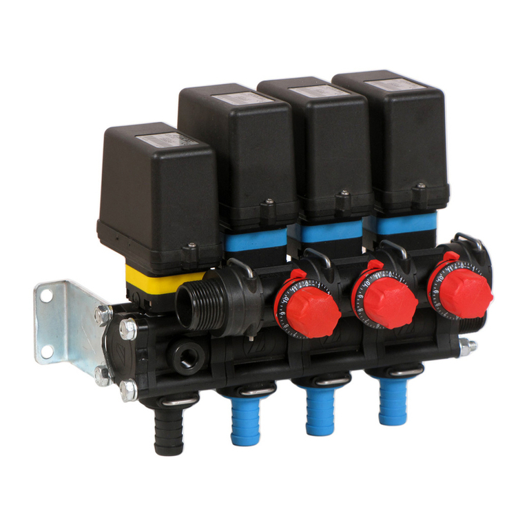
ARAG 853 Series Quick start guide

853 SERIES
VALVOLA A SFERA ELETTRICA CON COLLEGAMENTO CAN-BUS
ELECTRIC BALL VALVE WITH CAN-BUS CONNECTION
VANNE À BILLE ÉLECTRIQUE AVEC CONNEXION CAN-BUS
VÁLVULA ELÉCTRICA DE BOLA CON CONEXIÓN CAN-BUS
ELEKTRISCHES KUGELVENTIL MIT CAN-BUS-ANSCHLUSS
VÁLVULA DE ESFERA ELÉTRICA COM CONEXÃO CAN-BUS
INSTALLAZIONE, USO E MANUTENZIONE
INSTALLATION, USE AND MAINTENANCE
INSTALLATION, UTILISATION ET ENTRETIEN
INSTALACIÓN, USO Y MANTENIMIENTO
INSTALLATION, BETRIEB UND INSTANDHALTUNG
INSTALAÇÃO, USO E MANUTENÇÃO

2
SOMMARIO - CONTENTS - SOMMAIRE - SUMARIO - INHALTVERZEICHNIS - SUMÁRIO
Immagini - Images - Imágenes - Abbildungen - Imagens............................................... 3
Italiano................................................................................................................................ 5
English................................................................................................................................ 9
Français............................................................................................................................ 13
Español............................................................................................................................. 17
Deutsch ............................................................................................................................ 21
Português......................................................................................................................... 25
LEGENDA SIMBOLI - LEGEND SYMBOLS - LÉGENDE SYMBOLES
LEYENDA DE LOS SÍMBOLOS - SYMBOLVERZEICHNIS - LEGENDA DOS SÍMBOLOS
=Pericolo generico - Generic danger - Danger générique - Peligro general - Allgemeine Gefahr - Perigo
genérico
=Avvertenza - Warning - Avertissement - Advertencia - Hinweis - Aviso
Questo manuale è parte integrante dell’apparecchiatura alla quale fa riferimento e deve accompagnarla
sempre anche in caso di vendita o cessione. Conservatelo per ogni futuro riferimento; ARAG si riserva il
diritto di modicare le speciche e le istruzioni del prodotto in qualsiasi momento e senza alcun preavviso.
This manual is an integral part of the equipment to which it refers and must accompany the equipment in
case of sale or change of ownership. Keep it for future reference; ARAG reserves the right to modify the
specications and instructions regarding the product at any time and without prior notice.
Ce manuel est partie intégrante de l’appareillage auquel il se réfère et doit toujours l’accompagner même
en cas de vente ou de cession. Le conserver pour toute référence ultérieure; ARAG se réserve le droit de
modier les spécications et les instructions du produit à tout moment et sans aucun préavis.
Este manual es parte integrante del equipo al cual hace referencia y debe acompañarlo siempre,también en
caso de venta o cesión.Conservarlo para cualquier referencia futura;ARAG se reserva el derecho a modicar
las especicaciones y las instrucciones del producto en cualquier momento y sin aviso.
Diese Betriebsableitung ist ein zum darin beschriebenen Gerät gehörender Teil und muss ihm daher im Fall
seines Weiterverkaufs oder seiner Übergabe an einen anderen Benutzer beigelegt werden. Sie muss für
spätere Konsultationen aufbewahrt werden; ARAG behält sich das Recht vor, die das Produkt betreffenden
Spezikationen und Anleitungen jederzeit und ohne Vorankündigung ändern zu können.
Este manual é parte integrante da aparelhagem à qual faz referência e deve acompanhá-las sempre,mesmo
em caso de venda ou cessão.Conserve-o para futuras consultas; a ARAG se reserva o direito de alterar as
especicações e as instruções do produto a qualquer momento e sem algum aviso prévio.

3
IMMAGINI - IMAGES - IMAGENES - ABBILDUNGEN - IMAGENS
2-3 vie
2-3 ways
2-3 voies
2-3 vías
2-3 wege
2-3 vias
Fig. I
5 vie - 5 ways - 5 voies - 5 vías
5 wege - 5 vias
Fig. II
2 vie
2 ways
2 voies
2 vías
2 wege
2 vias
Y
X
102
CB
50 107
AM M
Fig. III
3 vie - attacco laterale
3 ways - side connection
3 voies - raccord latéral
3 vías - conexión lateral
3 wege - seitlicher Anschluss
3 vias - engate lateral
X
Y
50 107
CB
102
AM M
Fig. IV
3 vie - attacco inferiore
3 ways - bottom connection
3 voies - raccord inférieur
3 vías - conexión inferior
3 wege - Anschluss unten
3 vias - engate por baixo
102
C
B X
Y
50107
AM M
Fig. V
5 vie
5 ways
5 voies
5 vías
5 wege
5 vias
Y
X
50 107
C
B
102
AM M
Fig. VI
Fig. VII
*Non presente su tutti i modelli
*Not present on all models
*Pas présent sur tous les modèles
*No presente en todos los modelos
*Nicht an allen Modellen vorhanden
*Não existe em todos os modelos
2
1*
Fig. VIII

4
DATI TECNICI - TECHNICAL DATA - DONNÉES TECHNIQUES - DATOS TÉCNICOS -
TECHNISCHE DATEN - DADOS TÉCNICOS
VIE
WAYS
VOIES
VÍAS
WEGE
VIAS
COD.
CODE
CODE
CÓD.
ART.-NR.
CÓD.
Op. time @ 12 Vdc mm
Attacco, Coupling, Raccord,
Conexión, Anschluss, Engate
M (Fig. III - Fig. IV - Fig. V - Fig. VI)
Coppia di serraggio - Tightening torque
Couple de serrage - Par de apriete
Anzugsmoment - Torque de aperto
F
12345
(Fig. III - Fig. IV - Fig. V - Fig. VI)
mm mm mm mm mm
A
mm
B
mm
C
mm
X
mm
Y
mm Nm inch/lib
2-3
853xx 4xxx
1.4 sec.
(3 way bottom
connection
only: 2.8 sec)
3 A
32
T6 - - 42 - -
81 42 186 33 38 5 44
1" 10 - - - 25
1" 1/4 12 - - - -
853xx 5xxx 2.3 sec.
(3 way bottom
connection
only: 4.6 sec)
40 1" 1/2 12,5 25 - 49,5 20 93 52 192 40 49 4 36
853xx 6xxx 50 T7 - - 43 - - 118 61 210 57 60 5 44
2" 16 28 - 55 26
853xx 7xxx 65 2" 1/2 16 35 - - - 136 71 223 72 80 4 36
3" 19 38 - 59 28
5
85325 3x44
2.3 sec. 90°
4.6 sec. 180°
6.9 sec. 270°
3 A
20 T4 - - 24 - - 81 53 190 74 36 5 44
1" 10 - - - -
85325 5xxx 32
T6 - - 33 - -
93 72 210 100 46 10 891" 1/4 12 - - - -
1" 1/2 12,5 - - - -
853x5 6x66 40
T6 - - 33 - -
159 80 191 114 55 8 711" 1/2 -13 - - -
2" ----18
853x5 7x77 50 T7 - - 40 - - 168 80 223 51 101 12 106
2" 19 28 - 55 26
Tab. 1
VIE
WAYS
VOIES
VÍAS
WEGE
VIAS
ATTACCO
COUPLING
RACCORD
CONEXIÓN
ANSCHLUSS
ENGATE 12 3 4 5
2-3
T6
12 bar / 180 PSI 9 bar / 130 PSI 1" Flange 10 bar / 150 PSI
1"
1" 1/4
1" 1/2 10 bar / 150 PSI 2" Flange 10 bar / 150 PSI
2" 8 bar / 120 PSI 8 bar / 120 PSI 2" Flange full port 8 bar / 120 PSI
T7
2" 1/2 6 bar / 90 PSI --- 2" Flange full port 6 bar / 90 PSI
3" 5 bar / 75 PSI 3" Flange
5
1" 16 bar / 230 PSI 9 bar / 130 PSI Tab. 2
T4
1" 1/4
12 bar / 180 PSI 9 bar / 130 PSI1" 1/2
T6
2" 6 bar / 90 PSI 6 bar / 90 PSI
Tab. 3
1
Attacco lettato femmina
Female threaded tting
Raccord leté femelle
Toma roscada hembra
Anschluss mit Innengewinde
Conexão roscada fêmea
3
Attacco forchetta maschio
Male fork tting
Raccord à fourchette mâle
Toma de horquilla macho
Anschluss mit Einsteckgabel
Conexão com forquilha macho
2
Attacco lettato maschio
Male threaded tting
Raccord leté mâle
Toma roscada macho
Anschluss mit Außengewinde
Conexão roscada macho
Attacco morsetto tipo USA
American coupling
Connexion americaine
Tipo USA
Am. Kupplung
Tipo USA
54
Camlock

5
I
1 DESTINAZIONE D'USO
Le valvole elettriche serie 853 CAN-BUS sono state studiate per l’uso nel settore agricolo e sono
utilizzabili come deviatori di usso all’interno di un impianto in pressione per il trasporto di liquidi.
Queste valvole sono da intendersi per un utilizzo professionale.
2 LIMITAZIONI D'UTILIZZO
Le valvole elettriche serie 853 non sono utilizzabili:
- come valvole di sicurezza;
- in impianti attraversati da gas, vapori o similari;
- in impianti per atmosfere esplosive;
- per il contatto con gli alimenti;
- in impianti civili.
Questo dispositivo è progettato per l’installazione su macchine agricole per diserbo
e irrorazione.
L'apparecchiatura è progettata e realizzata in conformità alle direttive:
- Direttiva 2014/30/UE e successive modiche (EN ISO 14982 - Compatibilità
elettromagnetica - macchine agricole e forestali);
- Direttiva 2006/42/CE e successive modiche.
3 NORME DI SICUREZZA
ATTENZIONE:Tutte le operazioni di installazione e manutenzione devono essere
eseguite da personale preparato e fatte a circuito non in pressione e senza
alimentazione elettrica (connettore scollegato).
ARAG NON RISPONDE PER DANNI DI QUALSIASI NATURA CAUSATI DA
UN'INSTALLAZIONE ESEGUITA DA PERSONALE INESPERTO. NEL CASO DI DANNI
AL SISTEMA, CAUSATI DA UN'INSTALLAZIONE E/O COLLEGAMENTO ERRATI, SI
INTENDE RISOLTA OGNI FORMA DI GARANZIA.
EFFETTUARE OPERAZIONI DI INSTALLAZIONE E MANUTENZIONE SENZA AVER
TOLTO L'ALIMENTAZIONE ALLA VALVOLA PUÒ CAUSARE GRAVI LESIONI.
Non azionate a vuoto per lunghi periodi la valvola, alcune parti interne alla valvola
possono subire danni.
ARAG non può essere ritenuta responsabile per danni diretti o indiretti derivanti
dalla tipologia dei uidi utilizzati all'interno dell'impianto.
L’utilizzo di tali sostanze avviene sotto la piena responsabilità dell’operatore che
ha quindi l’obbligo di vericare le prescrizioni di sicurezza indicate dal produttore
del uido sulla confezione e di indossare adeguato equipaggiamento di protezione
individuale (guanti, tuta, stivali, casco, ecc.) in accordo alle prescrizioni di legge.
ARAG non può quindi in alcun modo rispondere di eventuali incidenti o danni
a persone, animali o cose conseguenti all’utilizzo improprio, non protetto o non
raccomandato dei prodotti impiegati.

6
I
4 PRESSIONE MASSIMA DI UTILIZZO
La pressione massima di utilizzo della valvola dipende dalla tipologia di attacco con la quale viene
fornita (Tab. 2 - Tab. 3).
Es.: se la valvola è dotata di attacchi differenti,per esempio due lettati ed un camlock,la pressione
massima di utilizzo sarà pari alla pressione massima dell'attacco con pressione inferiore.
Mod. 853D2 4A44 Femmina = 12 bar
Mod. 853D2 4D44 Femmina-Camlock = 10 bar
4.1 Dimensioni d'ingombro
Vedi Tab. 1 e Fig. III - Fig. IV - Fig. V - Fig. VI.
5 INCORPORAZIONE
L’installazione deve essere eseguita da personale specializzato. ARAG non risponde
per danni a persone, animali o cose causati da un’installazione eseguita da
personale impreparato.
• I componenti, i tubi le valole che verranno montati sull'impianto devono poter sopportare
una pressione maggiore della massima utilizzata nell'impianto.
• Una qualsiasi strozzatura sull'impianto potrebbe provocare una sovrapressione anomala.
• Assicuratevi che i tubi, i portagomma e le ange delle valvole abbiano un diametro
compatibile ed adeguato.
ATTENZIONE: non collegate i connettori elettrici alle valvole in quanto è un
operazione da effettuare in un secondo momento e solamente seguendo le
indicazioni riportate sul manuale del computer SYNCRO.
AZIONARE LA VALVOLA CON UNA O PIÙ ENTRATE/USCITE APERTE È MOLTO
PERICOLOSO E PUÒ CAUSARE INCIDENTI E GRAVI LESIONI ALL’INSTALLATORE O
MANUTENTORE.
NON INSERITE CORPI ESTRANEI O LE MANI ALL'INTERNO DEL FORO NELLA
SFERA MENTRE LA VALVOLA È COLLEGATA ALL'ALIMENTAZIONE ELETTRICA,
PERICOLO DI SCHIACCIAMENTO E AMPUTAZIONE.
ATTENZIONE: PER EVITARE DANNI ALL'IMPIANTO PREVEDETE ED ACCERTATEVI
CHE NESSUNA DELLE PARTI POSSA ANDARE ACCIDENTALMENTE A CONTATTO
CON ORGANI IN MOVIMENTO DELLA MACCHINA AGRICOLA.
5.1 Rotazione del motoriduttore
Il motoriduttore delle valvole 853 può essere ruotato a passi di 90° per posizionarlo nella posizione
più consona all'impianto nel quale vengono utilizzate le valvole.
La rotazione del motoriduttore è un intervento semplice ma delicato che, se eseguito incorrettamente
può rendere la valvola inutilizzabile o generare errori e/o incidenti nell'impianto.
É quindi molto importante eseguire tale operazione seguendo scrupolosamente tutte le indicazioni
ARAG declina ogni responsabilità per danni all'impianto, a persone, animali o cose
causate da modiche alla valvola a sfera e/o della mancata osservanza di quanto
descritto nei documenti citati.

7
I
5.2 Fissaggio
La valvola a sfera è predisposta per essere ssata mediante bulloni (Fig. I - Fig. II) del tipo indicato
al paragrafo 5.3.
- Inserite i bulloni nelle apposite sedi, quindi farli scorrere nella posizione di fermo per impedirne
la fuoriuscita.
Sulle valvole con attacchi da 1” ½ o più, è consigliabile utilizzare anche una rondella piana di
diametro adeguato (Ø 8 ISO 7089).
- Inserite i bulloni nei fori predisposti (vedi par. "5.4 Dima di foratura"), quindi avvitate i dadi e serrate
con forza.
Non sono ammesse altre tipologie di attacco diverse da quelle descritte.
5.3 Tipi di bulloni
Per il ssaggio della valvola utilizzate bulloni tipo:
• M8 ISO 4014/4017
• 5/16” ANSI B18.2
Con attacco maggiore di 1” ½:
• M8 ISO 4014/4017 + rondella M8 ISO 7089
• M8 ISO 4162
• 5/16” ANSI B18.2
5.4 Dima di foratura
Vedi Tab. 1 per la posizione dei punti di foratura per i bulloni di ssaggio.
5.5 Collegamenti idraulici
Togliete i tappi di protezione e collegate i tubi di entrata/uscita alla valvola, utilizzando le corrette
connessioni per la quale è predisposta. Si faccia attenzione, dove richiesto, al corretto inserimento
dell’O-ring fornito (bocche lettate).Se per qualsiasi motivo si vericassero perdite dai letti è possibile
rinforzare la tenuta utilizzando esclusivamente nastro in PTFE non sinterizzato.
ATTENZIONE: Per conoscere la massima pressione di utilizzo relativa alla
connessione scelta, fate riferimento alla Tab. 2 - Tab. 3.
Una volta collegate tutte le bocche della valvola, mettere prima in pressione l’impianto CON SOLA
ACQUA PULITA per vericare che non vi siano perdite dalle connessioni.

8
I
5.6 Collegamenti elettrici
Per collegare la valvola, utilizzate il cavo con connettore Tyco Superseal®a 4 poli per CAN-BUS.
1234
1 GND
2+12 Vdc
3 CAN L
4 CAN H
Fig. IX
Collegate il connettore della valvola a quello del cablaggio relativo; dopo esservi assicurati del
corretto inserimento premete no al bloccaggio (Fig. VII).
ATTENZIONE: ACCERTATEVI DI AVER INSERITO CORRETTAMENTE IL CONNETTORE
PER AVERE LA CERTEZZA DELLA TENUTA STAGNA.
ATTENZIONE: se la guarnizione non è posizionata correttamente, vi possono essere
inltrazioni d’acqua nel connettore e nella valvola con conseguente rischio di
danneggiamento del dispositivo.
6 USO
6.1 Comandi
Le speciche dei protocolli SAEJ1939 ed A-Net per inviare i comandi alla valvola possono essere
6.2 Segnalazioni del LED
Un LED posto sul connettore della valvola, ne indica lo stato:
VERDE
LAMPEGGIANTE
Un lampeggio intermittente della durata di 10 secondi indica che
la valvola è in attesa di acquisire un indirizzo CAN-BUS. Dopo il
periodo sopraindicato il led diventa verde sso, anche se non è
ancora stato acquisito l'indirizzo.
VERDE FISSO La valvola è congurata e funzionante.
ROSSO
LAMPEGGIANTE
Un lampeggio di colore rosso indica un malfunzionamento.
A seconda del numero dei lampeggi viene identicato un codice di
errore (vedere Tab. 4)

9
I
7 MANUTENZIONE
Le valvole a sfera elettriche della serie 853 CAN-BUS non necessitano di particolari manutenzioni.
Il lavaggio interno può essere eseguito quando si effettua quello dell’impianto al quale la valvola
è collegata. Nel caso in cui il manutentore dovesse aprire la valvola per vericarne la tenuta o per
eseguire pulizie straordinarie, è necessario, prima del rimontaggio, sostituire il kit guarnizioni relativo
alla bocca che si è aperta.
ATTENZIONE: rimontare la valvola senza sostituire il kit guarnizioni può ridurre la
tenuta sulla sfera interna e quindi causare perdite.
- Svitate i tiranti relativi alla bocca da aprire, quindi rimuovetela e togliete le guarnizioni interne e
l’O-ring inserito nella sede interna della angia rimossa.
- Riposizionate tutte le guarnizioni al loro posto, come indicato in Fig. VIII (la guarnizione (1) non
è presente su tutti i modelli) quindi richiudete la angia.
- Inserite i tiranti nei fori, rimontate le rondelle e avvitate i dadi serrandoli con le dita.
- Per garantire un corretto funzionamento, i dadi (2) devono essere stretti utilizzando una chiave
dinamometrica tarata secondo quanto riportato in Tab. 1.
- Ricollegate tutte le connessioni idrauliche.
- Ricollegate la connessione elettrica.
- Mettete in pressione l’impianto CON SOLA ACQUA PULITA e vericate che non vi siano perdite
dalle connessioni.
Ulteriori informazioni sulle operazioni di manutenzione straordinaria possono essere scaricate
gratuitamente dal sito internet www.aragnet.com.
8 INCONVENIENTI E RIMEDI
8.1 Lampeggi led
INCONVENIENTE STATO LED NUMERO
LAMPEGGI CAUSA RIMEDIO
La valvola perde o non vi è
sufficiente tenuta sulla sfera - -
Presenza di corpi
estranei.
• Vericare che non vi
siano corpi estranei,
eventualmente rimuoverli.
Tenute usurate. • Sostituire le tenute.

10
I
La valvola non risponde ai
comandi
Spento
-
Mancanza
alimentazione.
• Controllare le connessioni
ed i cablaggi.
• Sostituire il cavo; Se
il problema persiste,
contattare il Centro
Assistenza più vicino.
Collegamento errato dei
cablaggi.
• Controllare le connessioni
ed i cablaggi.
Tensione di
alimentazione inferiore
al minimo.
• Vericare che i cablaggi
siano proporzionati
all'impianto.
Verde sso
-
Motoriduttore guasto. • Sostituire il motoriduttore.
L'indirizzo CAN-BUS
assegnato alla valvola
è errato
• Ripetere la procedura di
assegnazione dell'indirizzo.
I comandi inviati sono
errati o inviati all'indirizzo
errato
• Controllare i comandi
inviati dal dispositivo di
controllo.
La connessione tra
valvola e dispositivo di
controllo è difettosa o
non adeguata
• Vericare le connessioni.
• Vericare che la struttura
del cablaggio risponda alle
speciche CAN-BUS 2.0.
• Vericare la presenza e
lo stato delle resistenze di
terminazione.
Rosso
lampeggiante
3Mancanza del segnale
di rotazione motore
• Rimuovere il motore e
controllare che la sfera
si muova liberamente; in
caso contrario procedere
alla manutenzione della
valvola o contattare il Centro
Assistenza più vicino.
• Riavviare la valvola.
8Rilevato assorbimento
anomalo di corrente
4 e 16 Problema al circuito del
controllo motore
• Riavviare la valvola;
se il problema persiste,
contattare il Centro
Assistenza più vicino.
La valvola non si ferma nel
punto prestabillito
Verde sso
-
I comandi inviati sono
errati o inviati all'indirizzo
errato
• Controllare i comandi
inviati dal dispositivo di
controllo.
Rosso
lampeggiante
2Sensore angolare non
calibrato
• Riavviare la valvola;
se il problema persiste,
contattare il Centro
Assistenza più vicino.
5Problema sul sensore
angolare
6Problema sul sensore
angolare
7Errore della misura
dell'angolo
13
La valvola non riesce a
raggiungere la posizione
richiesta (errore
maggiore di 1°)

11
I
La valvola funziona
correttamente, ma il led
rosso lampeggia Rosso
lampeggiante
12 Rilevata temperatura
troppo alta • Vericare le condizioni di
utilizzo: in queste condizioni
la valvola potrebbe non
fornire le prestazioni
specicate.
14
Tensione di
alimentazione troppo
alta
15
Tensione di
alimentazione troppo
bassa
Tab. 4
9 SMALTIMENTO
Da smaltire in conformità alla legislazione vigente nel paese in cui si esegue tale operazione.
10 DICHIARAZIONE DI CONFORMITÀ
La dichiarazione di conformità é disponibile all’indirizzo internet www.aragnet.com, nella relativa
sezione.

12
GB
1 FIELD OF APPLICATION
The CAN-BUS 853 series electric valves are designed for use in the agricultural sector and can be
used as ow switches in a system under pressure for conveying liquids.
These valves are for professional use only.
2 LIMITATIONS OF USE
The 853 series electric valves may not be used:
- as safety valves;
- in systems where gases, vapors, or similar pass through;
- in systems for explosive atmospheres;
- in contact with food stuff;
- in civil systems.
This device is designed to work on agricultural machinery for spraying and crop
spraying applications.
The equipment is designed and manufactured according to:
- Directive 2014/30/EU and subsequent amendments (EN ISO 14982 - Electromagnetic
Compatibility - agricultural and forest machines);
- Directive 2006/42/EC and following amendments.
3 SAFETY REGULATIONS
WARNING: All installation and maintenance operations must be carried out by
qualied personnel with circuit not under pressure and without power supply
(connector disconnected).
ARAG IS NOT LIABLE FOR ANY DAMAGE RESULTING FROM INSTALLATION
BY UNSKILLED PERSONNEL. ANY SYSTEM DAMAGE CAUSED BY A WRONG
INSTALLATION AND/OR CONNECTION AUTOMATICALLY VOIDS THE WARRANTY.
CARRYING OUT INSTALLATION AND MAINTENANCE OPERATIONS WITHOUT
DISCONNECTING THE VALVE FROM ITS POWER SUPPLY MAY CAUSE SEVERE
INJURY.
Do not operate the valve with no load for long periods of time, as this might damage
the components inside the valve.
ARAG declines any responsibility for direct or indirect damage deriving from the
type of uids used in the system.
The use of such substances is made under the full responsibility of the operator,
who therefore must follow the safety measures indicated by the uid manufacturer
on the package and wear suitable personal safety equipment (gloves, coverall, boots,
helmet, etc.) in compliance with the law provisions.
ARAG may not in any way be held responsible for accidents or damage to persons,
animals or objects caused by improper, unprotected, or non-recommended use of
the products utilized.

13
GB
4 MAXIMUM OPERATING PRESSURE
The maximum operating pressure of the valve depends on the type of coupling it is tted with
(Tab. 2 - Tab. 3).
E.g.: If the valve has different couplings,for instance two threaded couplings and one camlock,the
maximum operating pressure will be equal to the maximum pressure permitted by the coupling
with lower pressure.
Mod. 853D2 4A44 Female = 12 bar
Mod. 853D2 4D44 Female-Camlock = 10 bar
4.1 Overall dimensions
Refer to Tab. 1 and Fig. III - Fig. IV - Fig. V - Fig. VI.
5 INSTALLATION
Installation must be carried out by specialized personnel. ARAG may not be held
responsible for any damage to persons, animals, or objects caused by installation
carried out by unqualied personnel.
• The components, pipes and valves that will be installed in the system must withstand a
pressure higher than the maximum one of the system.
• Any constriction in the system may lead to a faulty over-pressure.
• Make sure that hoses, hose tails and valve anges feature a suitable and compatible diameter.
WARNING: do not connect the electric connectors to the valves.This operation must
be performed at a later stage and only by following the instructions provided in the
SYNCRO computer manual.
OPERATING THE VALVE WITH ONE OR MORE INLETS/OUTLETS OPEN IS VERY
DANGEROUS AND CAN CAUSE ACCIDENTS AND SERIOUS INJURIES TO THE
INSTALLATION OR MAINTENANCE PERSONNEL.
DO NOT INSERT ANY FOREIGN BODIES OR YOUR HANDS INTO THE HOLE OF THE
BALL WHILE THE VALVE IS CONNECTED TO THE ELECTRIC POWER SUPPLY, AS
THIS COULD LEAD TO CRUSHING OR AMPUTATION.
WARNING:TO AVOID DAMAGING THE SYSTEM, MAKE SURE THAT NONE OF THE
PARTS COMES INTO CONTACT WITH MOVING PARTS OF THE FARMING MACHINE.
5.1 Geared motor rotation
The geared motor of the 853 valves can be turned in 90°-steps to set it in the most suitable position
according to the system the valves are installed in.
Turning the geared motor is a simple but delicate operation, which may impair valve operation or
lead to system errors and/or accidents if performed in the wrong way.
It is therefore very important to perform this operation by thoroughly observing the instructions
ARAG will not be held responsible for any damage to the system, people, animals
or objects caused by modications to the ball valve and/or failure to follow the
guidelines outlined in the mentioned documents.

14
GB
5.2 Attachment
The ball valve is factory set to be attached using bolts (Fig. I - Fig. II) of the type indicated in section 5.3.
- Insert the bolts into their respective seats and turn them to the stop position to prevent them from
coming out.
On valves with 1” ½ or larger coupling, we recommend also using a at washer of suitable diameter
(Ø 8 ISO 7089).
- Insert the bolts into the holes provided (refer to section "5.4 Drilling template"), then tighten the
nuts thoroughly.
No other types of coupling are permitted than those described.
5.3 Types of bolts
To attach the valve use bolts of the following types:
• M8 ISO 4014/4017
• 5/16” ANSI B18.2
With coupling greater than 1” ½:
• M8 ISO 4014/4017 + M8 ISO 7089 washer
• M8 ISO 4162
• 5/16” ANSI B18.2
5.4 Drilling template
Refer to Tab. 1 for the position of the drilling points for the attachment bolts.
5.5 Hydraulic connections
Remove the protective caps and connect the inlet/outlet hoses to the valve, using the correct
connections for which it is set. Take special care, where requested, to insert the supplied O-ring
correctly (threaded ends). If, for any reason, the pipes leak at connection points, apply unsintered
PTFE tape to improve sealing.
WARNING: For the maximum operating pressure for the chosen connection, refer to
Tab. 2 - Tab. 3.
Once all the couplings of the valve are connected, put the system under pressure ONLY WITH
CLEAN WATER rst to make sure that the connections are not leaking.

15
GB
5.6 Wiring connections
To connect the valve, use the cable with Tyco Superseal® 4-pole connector for CAN-BUS.
1234
1 GND
2+12 Vdc
3 CAN L
4 CAN H
Fig. IX
Connect the valve connector to that of the relevant harness; make sure it is correctly tted and push
it until it locks in place (Fig. VII).
WARNING: CHECK THAT THE CONNECTOR IS FITTED CORRECTLY TO ENSURE A
PROPER SEALING.
WARNING: If the gasket is not positioned correctly, there may be inltrations of water
in the connector and in the valve, with the consequent risk of damage to the device.
6 USE
6.1 Commands
The specications of SAEJ1939 and A-Net protocols to send commands to the valve can be
requested by contacting the ARAG technical support department to the following address: support@
aragnet.com.
6.2 LED signals
A LED positioned on valve connector indicates the relevant status:
GREEN BLINKING
An intermittent ashing lasting 10 seconds indicates that the valve is
waiting to acquire a CAN-BUS address. After the aforementioned
period, the LED turns solid green, even if the address has not yet
been acquired.
GREEN STEADY
ON The valve is congured and functioning.
RED
BLINKING
A red ashing indicates a malfunction.
An error code is identied according to the number of blinks
(refer to Tab. 4)

16
GB
7 MAINTENANCE
The electric ball valves of the 853 CAN-BUS series do not require any particular maintenance.
Internal cleaning can be carried out when the system to which the valve is connected is cleaned.
If the maintenance man needs to open the valve to check the seal or for extraordinary cleaning, before
tting it back you must replace the seal kit of the orice that was opened.
WARNING: Fitting back the valve without replacing the gasket kit can reduce the
sealing on the internal ball and therefore cause leaks.
- Unscrew the bolts related to the orice to be opened, then remove it and take out the inner gaskets
and the O-ring inserted in the internal seat of the ange that has been removed.
- Re-position all the gaskets in their seats, as shown in Fig. VIII (gasket (1) is not present on all
models), then close the ange.
- Insert the bolts in the holes, t back the washers and screw in the nuts by hand.
- To ensure correct operation, the nuts (2) must be tightened using a dynamometric spanner calibrated
according to what indicated in Tab. 1.
- Reconnect all the hydraulic connections.
- Restore electric power supply.
- Put the system under pressure ONLY WITH CLEAN WATER and check that the connections are
not leaking.
Further information on the special maintenance operations can be downloaded free of charge
from our Website www.aragnet.com.
8 TROUBLESHOOTING
8.1 LED blinks
TROUBLE LED
STATUS
NUMBER
OF BLINKS CAUSE SOLUTION
The valve leaks or the seal
of the ball is not enough - -
Presence of foreign
bodies.
• Make sure there are no
foreign bodies; if so, remove
them.
Worn seals. • Replace the seals.

17
GB
The valve does not
respond to commands
Off
-
No power supply.
• Check the connections and
the cables.
• Replace the cable; If the
problem persists, contact
your nearest Service Center.
Wrong wiring harness
connection.
• Check the connections and
the cables.
Power supply voltage
lower than the minimum
value.
• Make sure that the
harnesses are suitable for
the system.
Green steady on
-
Geared motor broken. • Replace the geared motor.
The CAN-BUS address
assigned to the valve is
wrong.
• Repeat the address
assignment procedure.
The sent commands are
wrong or have been sent
to the wrong address
• Check the commands sent
by the control device.
The connection between
valve and control device
is faulty or not suitable.
• Check connections.
• Make sure that the harness
structure complies with the
CAN-BUS 2.0 specications.
• Check for the presence
and conditions of
terminating resistors.
Red blinking
3 No motor rotation signal. • Remove the motor and
make sure that the ball can
move freely; on the contrary,
perform valve maintenance
operations or contact your
nearest Service Center.
• Restart the valve .
8Abnormal current
absorption detected.
4 and 16 Problem on motor
control circuit.
• Restart the valve; if the
problem persists, contact
your nearest Service Center.
The valve does not stop at
the preset point
Green steady on
-
The sent commands are
wrong or have been sent
to the wrong address.
• Check the commands sent
by the control device.
Red blinking
2Angle sensor not
calibrated
• Restart the valve; if the
problem persists, contact
your nearest Service
Center.
5 Problem on angle sensor
6 Problem on angle sensor
7Error in angle
measurement
13
The valve cannot reach
the requested position
(error greater than 1°)
The valve works correctly,
but the red LED blinks
Red blinking
12 Too a high temperature
has been detected • Check the operating
conditions: under these
conditions the valve
could not have the
speciedperformance.
14 Power supply voltage
too high
15 Power supply voltage
too low
Tab. 4

19
F
1 UTILISATION PRÉVUE
Les vannes électriques série 853 CAN-BUS ont été étudiées et mises au point pour être utilisées
dans le secteur agricole et comme déviateurs de débit dans un système sous pression pour le
transport de liquides. Ces vannes sont destinées à un usage professionnel.
2 LIMITATIONS D’UTILISATION
Les vannes électriques série 853 ne peuvent pas être utilisées :
- comme vannes de sécurité ;
- dans des installations traversées par des gaz, vapeurs ou similaires ;
- dans des installations pour atmosphères explosives ;
- pour le contact avec les aliments ;
- dans des installations civiles.
Ce dispositif est conçu pour être installé sur des machines agricoles de désherbage
et pulvérisation.
L’appareillage est conçu et fabriqué conformément aux Directives énoncées ci-dessous.
- Directive 2014/30/UE et modications suivantes (EN ISO 14982 Compatibilité
électromagnétique - machines agricoles et équipements forestiers) ;
- Directive 2006/42/CE et modications suivantes.
3 CONSIGNES DE SÉCURITÉ
ATTENTION : toutes les opérations d’installation et d’entretien doivent être
effectuées par un personnel compétent et lorsque le circuit n’est ni sous pression ni
sous tension électrique (connecteur débranché).
AUCUNE RESPONSABILITÉ NE PEUT ENGAGER ARAG POUR DES DOMMAGES
DE TOUTE NATURE CAUSÉS PAR UNE INSTALLATION EFFECTUÉE PAR UN
PERSONNEL INEXPÉRIMENTÉ.TOUT DOMMAGE AU SYSTÈME CAUSÉ PAR
UNE MAUVAISE INSTALLATION ET / OU CONNEXION, RENDRA LA GARANTIE
AUTOMATIQUEMENT NULLE ET CADUQUE.
EFFECTUER LES OPÉRATIONS D’INSTALLATION ET D'ENTRETIEN SANS
AVOIR COUPÉ L'ALIMENTATION DE LA VANNE PEUT PROVOQUER DE GRAVES
BLESSURES.
Ne pas actionner la vanne à vide pendant de longues périodes sous peine
d'endommager certaines pièces à l'intérieur de la vanne.
ARAG ne peut pas être tenue pour responsable des dommages causés directement
ou indirectement par le type de uides utilisés à l'intérieur de l'équipement.
L’utilisation de ces substances se fait sous l'entière responsabilité de l'opérateur,
lequel est donc tenu de vérier les consignes de sécurité indiquées par le fabricant
du liquide sur l’emballage ainsi que de porter un équipement de protection
individuelle adéquat (gants, combinaison, bottes, casque, etc.) conformément aux
dispositions de la loi.
ARAG ne peut donc en aucun cas répondre pour des éventuels accidents ou
dommages causés aux personnes, aux animaux ou aux choses à la suite d’un usage
impropre, non conforme, non protégé ou non recommandé des produits.

20
F
4 PRESSION D’UTILISATION MAXIMALE
La pression d’utilisation maximale de la vanne dépend du type de raccord dont elle est équipée
(Tab. 2 - Tab. 3).
Exemple : si la vanne est munie de raccords différents,soit deux letés et un camlock,la pression
d’utilisation maximale sera égale à la pression maximale du raccord ayant une pression inférieure.
Mod. 853D2 4A44 Femelle = 12 bars
Mod. 853D2 4D44 Femelle-Camlock = 10 bars
4.1 Dimensions d'encombrement
Voir Tab. 1 et Fig. III - Fig. IV - Fig. V - Fig. VI.
5 INSTALLATION
L’installation doit être réalisée par un personnel compétent. ARAG décline toute
responsabilité pour les dommages causés aux personnes, aux animaux ou aux
choses par une installation réalisée par un personnel non qualié.
• Les composants, les tuyaux et les vannes qui seront installés sur l'équipement doivent être
en mesure de supporter une pression supérieure à celle maximale utilisée dans l'équipement.
• Tout étranglement présent sur l'équipement pourrait causer une surpression anormale.
• S'assurer que les tuyaux, les raccords et les brides des vannes ont un diamètre compatible
et adéquat.
ATTENTION : ne pas relier les connecteurs électriques aux vannes car cette
opération doit être effectuée dans un deuxième temps et seulement en suivant les
indications contenues dans le manuel de l'ordinateur SYNCRO.
ACTIONNER LA VANNE LORSQU’UNE OU PLUSIEURS ENTRÉES / SORTIES SONT
OUVERTES EST UNE OPÉRATION EXTRÊMEMENT DANGEREUSE QUI PEUT
PROVOQUER DES ACCIDENTS ET DE GRAVES BLESSURES À L'INSTALLATEUR OU
L’OUVRIER PRÉPOSÉ À L’ENTRETIEN.
NE PAS INSÉRER DES CORPS ÉTRANGERS NI METTRE LES MAINS À L’INTÉRIEUR
DU TROU DANS LA BILLE LORSQUE LA VANNE EST SOUS TENSION ÉLECTRIQUE
SOUS PEINE D’ÉCRASEMENT ET D’AMPUTATION.
ATTENTION : POUR ÉVITER TOUT DOMMAGE À L'ÉQUIPEMENT VÉRIFIER ET FAIRE
EN SORTE QU'UNE PARTIE N'ENTRE ACCIDENTELLEMENT EN CONTACT AVEC DES
ORGANES EN MOUVEMENT DE LA MACHINE AGRICOLE.
5.1 Rotation du motoréducteur
Le motoréducteur des vannes 853 peut être tourné par pas de 90° pour le placer dans la position
la plus adéquate à l'équipement dans lequel les vannes sont utilisées.
La rotation du motoréducteur est une intervention simple mais délicate, laquelle si exécutée d'une
manière incorrecte peut compromettre le bon fonctionnement de la vanne ou causer des erreurs
et/ou accidents dans l'équipement.
Il est donc très important d'effectuer cette opération en suivant scrupuleusement toutes les indications
ARAG décline toute responsabilité pour les dommages causés à l'équipement, aux
personnes, aux animaux ou aux choses, à la suite de modications apportées à la
vanne à bille et/ou de l’inobservation de toutes les prescriptions énoncées dans les
documents susdits.
Other manuals for 853 Series
1
This manual suits for next models
8
Table of contents
Languages:
Other ARAG Control Unit manuals

ARAG
ARAG IBX100 4679004 Quick start guide

ARAG
ARAG VISIO BLC Installation and operating instructions

ARAG
ARAG 863 Series Quick start guide

ARAG
ARAG 863T Series Quick start guide

ARAG
ARAG 463 Series Quick start guide

ARAG
ARAG BRAVO 300S User manual

ARAG
ARAG 453 Series User guide

ARAG
ARAG IBX100 4679004 User manual

ARAG
ARAG IBX100 4679004 Quick start guide

ARAG
ARAG 8537 Series Quick start guide