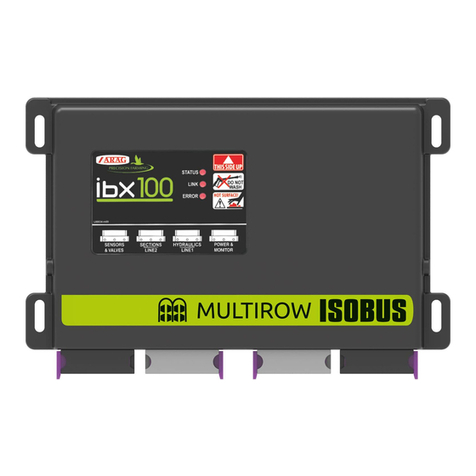
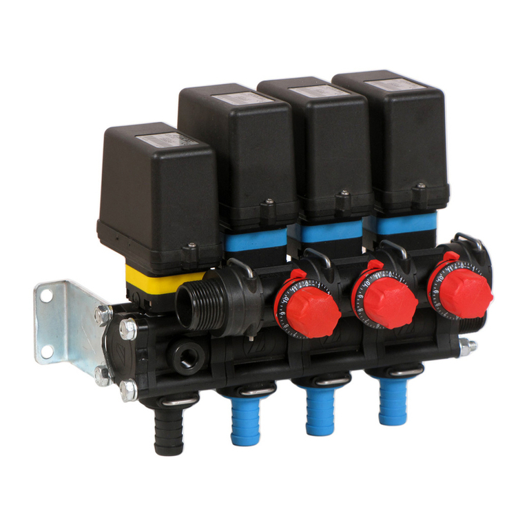
ARAG IBX100 4679004 Quick start guide

INSTALLATION, USE AND MAINTENANCE
4679005
IBX100 ELECTRONIC CONTROL UNIT
Object Pool rel. 1.4.0

2
• LEGEND OF SYMBOLS
=Generic danger
=Warning
ECU =IBX100 remote control unit
VT =Virtual Terminal
OP =Object Pool
This manual is an integral part of the equipment to which it refers and must accompany the equipment in case of sale or change of ownership. Keep it for any
future reference; ARAG reserves the right to modify product specications and instructions at any moment and without notice.
WARNING:
THE NATIVE CONTROLS INSIDE YOUR VIRTUAL
TERMINAL HAVE THE PRIORITY ON ALL THE CONTROLS
DERIVING FROM THE IBX100. PLEASE, KEEP THIS IN
MIND WHEN PROGRAMMING AND USING THE PRODUCT.
LEGEND OF SYMBOLS

3
CONTENTS
1 Manual use modes ...................................................................................................................................................................4
2 Limitations ................................................................................................................................................................................4
3 Responsibility ...........................................................................................................................................................................4
4 Risks and protections before assembly.................................................................................................................................4
5 Intended use .............................................................................................................................................................................4
6 Precautions ...............................................................................................................................................................................4
7 Package content .......................................................................................................................................................................4
8 Position of farming machine ...................................................................................................................................................5
8.1 System typical composition..............................................................................................................................................5
8.2 IBX 100 control unit fixing ................................................................................................................................................7
9 Wiring connections ..................................................................................................................................................................8
9.1 General precautions for a correct harness position .........................................................................................................8
9.2 Control unit (ECU) connection .........................................................................................................................................8
9.3 Wiring harness connection ..............................................................................................................................................9
9.4 Hydraulic valve connection ..............................................................................................................................................9
10 ISOBUS system cable connection ........................................................................................................................................10
10.1 Connection of in-cab cable ............................................................................................................................................10
10.2 Connection of ISOBUS cable.........................................................................................................................................10
11 “OBJECT POOL” loading .......................................................................................................................................................11
12 Hydraulic controls ..................................................................................................................................................................11
13 Control layout .........................................................................................................................................................................12
14 MENU ....................................................................................................................................................................................13
14.1 Settings..........................................................................................................................................................................14
14.1.1 AUX configuration: SWITCH BOX............................................................................................................................................. 14
14.1.2 AUX configuration: Joystick ...................................................................................................................................................... 15
14.1.3 Hydraulic functions................................................................................................................................................................... 15
14.2 User level.......................................................................................................................................................................16
14.2.1 Entering the PIN number.......................................................................................................................................................... 16
14.2.2 Removing the PIN number ....................................................................................................................................................... 17
14.3 System status ................................................................................................................................................................18
14.3.1 License Registration................................................................................................................................................................. 18
14.3.2 Restart ECU.............................................................................................................................................................................. 19
14.3.3 Delete OP ................................................................................................................................................................................. 19
14.4 Backup management.....................................................................................................................................................20
14.4.1 Create backup.......................................................................................................................................................................... 20
14.4.2 Restore backup ........................................................................................................................................................................ 20
14.4.3 Reset to Arag factory defaults .................................................................................................................................................. 21
15 JOYSTICK: Arag DEFAULT functions ....................................................................................................................................22
15.1 Joystick Explorer ............................................................................................................................................................22
15.2 Joystick Explorer 2 .........................................................................................................................................................23
16 Maintenance / diagnostics / repairs ......................................................................................................................................24
16.1 Cleaning rules................................................................................................................................................................24
16.2 LED status key...............................................................................................................................................................24
16.3 Troubleshooting..............................................................................................................................................................24
17 Technical data.........................................................................................................................................................................25
18 End-of-life disposal ................................................................................................................................................................25
19 Guarantee terms .....................................................................................................................................................................25
20 EU declaration of conformity.................................................................................................................................................25

4
FOREWORD
1 MANUAL USE MODES
The section of this manual dedicated to the installation contains information for installers. For this reason we have used technical terms without pro-
viding explanations which would be necessary for end users only.
THE INSTALLATION MUST BE CARRIED OUT BY AUTHORIZED AND SKILLED PERSONNEL ONLY. ARAG IS NOT RESPONSIBLE
FOR ANY OPERATION SPECIFIED IN THIS MANUAL CARRIED OUT BY UNAUTHORIZED OR UNSKILLED PERSONNEL.
2 LIMITATIONS
The descriptions of the assembly phases refer to a "general" Virtual Terminal, so specic models will not be mentioned, unless a certain installation
procedure concerns exclusively one VT type.
3 RESPONSIBILITY
The installer must carry out "workmanlike" installations and ensure to the end user the perfect operation of the whole system both with ARAG
components only and other brands' components.
ARAG always recommends using its components to install control systems.
The installer will be held responsible for any malfunction if he decides to use other brands' components even without actually changing the system
parts or harness.
The compatibility check with components and accessories of other manufacturers shall be carried out by the installer.
If the ARAG components installed together with other brands' components get damaged because of what stated above, no direct or indirect warranty
will be provided.
4 RISKS AND PROTECTIONS BEFORE ASSEMBLY
The installation works relating to the job computer, except the main connection (ISOBUS system Chap. 10) must be done with
battery disconnected, using suitable tools and any individual protection equipment deemed necessary.
Use ONLY clean water for treatment tests and simulations: using chemicals during simulated treatment runs can seriously injure
persons in the vicinity.
5 INTENDED USE
The equipment you have purchased is a standard ISOBUS system compliant with ISO11783 to be applied to a crop spraying boom.
This device is designed to work on agricultural machinery for spraying and crop spraying applications.
The machine is designed and built in compliance with ISO 14982 standard (Electromagnetic compatibility - Forestry and farming
machines), harmonized with 2014/30/UE Directive.
6 PRECAUTIONS
• Do not aim water jets at the equipment.
• Do not use solvents or fuel to clean the case outer surface.
• Do not clean equipment with direct water jets.
• Comply with the specied power voltage (12 VDC).
• In case of voltaic arc welding, remove connectors from the device and disconnect the power cables.
• Only use ARAG genuine spare parts and accessories.
7 PACKAGE CONTENT
Fi g . 1
Control unit
Harnesses must be ordered separately (Ref. ARAG general catalog).

5
INSTALLATION
8 POSITION OF FARMING MACHINE
8.1 System typical composition
To connect all parts of the system correctly, make sure to use the proper connection cables.
Consider any variants depending on system type.
ISOBUS INSTALLATION DIAGRAM: IBX100 HYDRAULIC
VIRTUAL
TERMINAL
ISOBUS
PLUG
1
2
3
5
4
PART NO. 4679005
Fi g . 2
Legend of connection cables:
1Standard ISOBUS connector (ISOBUS PLUG)
2Connection cable IBX100 HYDRAULIC / Hydraulic unit
3Hydraulic unit
4Switch panel
5Explorer Joystick / Explorer 2 Joystick
CONTINUES > > >

6
INSTALLATION
ISOBUS INSTALLATION DIAGRAM: IBX100 HYDRAULIC - IBX100 SPRAYER
VIRTUAL
TERMINAL
ISOBUS
PLUG
1
23
4
6
COD. 4679005
Fi g . 3
COD. 4679004
Legend of connection cables:
1Standard ISOBUS connector (ISOBUS PLUG)
2Connection cable IBX100 HYDRAULIC / ISOBUS PLUG / IBX100 SPRAYER
3Connection cable for hydraulic unit
4Hydraulic unit
5Switch panel
6Explorer Joystick / Explorer 2 Joystick

7
INSTALLATION
8.2 IBX 100 control unit xing
Secure the control unit on the back of the machine, close to the control unit and the hydraulic unit.
Consider all necessary connections of the device (par. 9.3), the cable length, and make sure there is enough space for connec-
tors and cables.
For any reference to the system conguration read par. 8.1.
Respect the mounting direction of the control units, as specied in Fi g . 4 (connectors shall be facing down).
Fix the ECU using the 4 bolts tted into their slots (A, Fi g . 4 ).
No other type of assembly is allowed.
Fi g . 4
Unit of measurement: mm
Fi g . 5
DIMENSIONS

8
INSTALLATION
9 WIRING CONNECTIONS
• Use original ARAG harnesses only.
• Take care not to break, pull, tear or cut the cables.
• Use of unsuitable cables not provided by ARAG automatically voids the warranty.
• ARAG is not liable for any damage to the equipment, persons or animals caused by failure to observe the above instructions.
9.1 General precautions for a correct harness position
• Securing the cables:
- secure the harness so that it does not interfere with moving parts;
- route the harnesses so that they cannot be damaged or broken by machine movements or twisting.
• Routing the cables to protect against water inltrations:
- the cable branches must ALWAYS be facing down.
• Fitting the cables to the connection points:
- Do not force the connectors by pushing too hard or bending them: the contacts may be damaged and system operation may be compromised.
Use ONLY the cables and accessories indicated in the catalog, having technical features suitable for the use to be made of them.
9.2 Control unit (ECU) connection
WARNING: DO NOT CONNECT ISOBUS CONNECTOR (Fig. 9 on page 10).
THIS CONNECTION MUST BE CARRIED OUT LATER, ONLY AFTER INSTALLING ALL THE COMPONENTS (Chap. 10 ISOBUS
system cable connection).
Connect harnesses as specied in par. 9.3; each one of them shall be connected to the corresponding socket on the remote control unit.
Close the unused connectors with the relevant caps supplied in the package.
If they prove hard to insert, do not force them, but check the shown position.
Fi g . 6
Some connectors are supplied with separated slide.
Manually insert the slide in the most convenient position for connector insertion and removal.
• Open connector slide (1,Fi g . 6 ).
• Position connector (2) and insert it inside socket (3) then press: during this operation, take special care not to bend electric contacts.
• Close slide (4) until it locks in place.

9
9.3 Wiring harness connection
Fi g . 7
9.4 Hydraulic valve connection
Fi g . 8
The system can control up to 9 hydraulic functions through double-acting valves.
Fix the connectors to the relevant valves according to the initials indicated in your assembly general diagram (par. 5.1).
• Position seal (1) onto connector (2), then connect the latter pressing it fully home (3):
during this operation, take special care not to bend valve electric contacts.
• Insert screw inside connector, and screw it (4) until it is tightened.
The function of each switch on the hydraulic function control panel is described below.
• Connect the connector marked with “DD” to the pilot valve, and then the other connectors, as specied on the table:
CONTROL MOVEMENT CONNECTOR
Section movement
1 - 2 - 3 - 4 - 5 - 6
Opening 1 ÷ 6 A
Closing 1 ÷ 6 C
Boom height
Opening AA
Closing AC
Boom lock
Opening BA
Closing BC
Boom leveling
Opening CA
Closing CC
INSTALLATION
NUM CONNECTION POINTS
1Hydraulic unit
2VT / IBX100 Sprayer ISOBUS

10
INSTALLATION
10 ISOBUS SYSTEM CABLE CONNECTION
1. Connect the ISOBUS and IN-CAB cables.
2. Turn the VT on.
3. Wait for the OP complete loading (para. 11 ).
IN-CABIN-CAB
CONNECTIONCONNECTION
ISOBUSISOBUS
CONNECTIONCONNECTION
Fi g . 9
10.1 Connection of in-cab cable
Use the cable supplied in the auxiliary input package*.
Connection: Fit the connectors (in-cab connection in Fi g . 9 ), ensure they are correctly in place and turn the ring nut clockwise until blocking them.
*ARAG Auxiliary Input control system is not compulsory on all systems, and must thus be ordered separately.
Some VTs allow controlling section valves directly from monitor touch-screen panel.
10.2 Connection of ISOBUS cable
Use cable ISOBUS PLUG ("Fig. 2"-"Fig. 3", para. 8.1 System typical composition).
Connections: x the connectors (ISOBUS connection in Fi g . 9 ); make sure they are correctly tted and push until locking them.

11
"OBJECT POOL" LOADING - HYDRAULIC CONTROLS
11 “OBJECT POOL” LOADING
Images and the relevant description texts contained in this manual are given as a reference as they can vary depending on the
Virtual Terminal used. If the descriptions do not correspond to the text displayed in your Virtual Terminal, refer to the manual
attached to the latter.
ECU OP loading.
Fi g . 10
Press to enter the main
screen.
Wait for the ECU OP to be
fully loaded.
Fi g . 11
12 HYDRAULIC CONTROLS
Once OP loading is complete, if ONLY the hydraulic function is enabled on the device, this screen will be displayed as main page.
The main screen varies based on the active functions (para. 14.3.1)
Fi g . 12
Boom release
Boom lock
Boom counter-clockwise leveling
Boom clockwise leveling
Increase boom height
Decrease boom height
Boom section movement:
opening
Boom section movement:
closing

12
USING THE KEYS
13 CONTROL LAYOUT
Takes to menu screen
Goes to the following page
Goes back to the previous page
ENTERING A NUMERICAL VALUE
Icons are given as a reference as they can vary depending on the Virtual Terminal used:
Before system setup, check:
• that all components are correctly installed;
• the correct connection to the power source;
• the component connection.
Failure to correctly connect system components or to use specied components might damage the device or its components.
Upon rst switching on, enter the device basic settings.
ONCE ALL MODIFICATIONS HAVE BEEN COMPLETED,THE SYSTEM WILL PERFORM AN AUTOMATIC SAVING.

13
MENU
14 MENU
Allows accessing the following pages:
- Hydraulic controls
- User level
- System status
- Settings
1
Fi g . 13
From the main page, press button 1to access the Menu.
Fi g . 14

14
14.1 Settings
Fig. 15
Allows setting the auxiliary control and the hydraulic functions.
1
2
Fig. 16
1Allows detecting the connected Auxiliary input.
2
Allows setting some functions regarding the hydraulic outputs.
14.1.1 AUX conguration: SWITCH BOX
1
Fi g . 17
The system detects the presence of a switch box.
1Press button to assign the ARAG preset functions to the switch box.
To display the assigned functions, use the OP (Object Pool) of the switch box.
Function assignment can be customized through your VT.
SETTINGS

15
HYDRAULIC CONTROLS
14.1.2 AUX conguration: Joystick
2
1
Fig. 18
The system detects the presence of the Joystick.
1Enables / Disables the limitation based on the number of hydraulic sections you wish
to manage:
Disable button 1to remove the limitation and allow the management of 9 hydraulic
sections
2Press button to assign the ARAG preset functions to the Joystick.
To display the assigned functions, use the OP (Object Pool) of the Joystick.
Function assignment can be customized through your VT.
Use the Joystick "Object Pool" to display the assigned functions.
"par. 15.1 - pag. 22", "par. 15.2 - pag. 23"
14.1.3 Hydraulic functions
Bypass valve
Allows selecting the functions that automatically activate the drain valve when operated:
Enables / Disables
the drain valve "Fig. 19"
Look sens. setting
Allows you to select the hydraulic functions to be disabled when the boom status detected by IBX100 Sprayer is LOCKED. "Fig. 20"
These settings are applied only in case of installation of IBX100 Hydraulics with IBX100 Sprayer, in case the latter has connected a sensor that detects
the LOCKED/NON LOCKED status of the boom.
NOTE: In no case is the direct connection of a "boom lock" sensor to IBX100 Hydraulics foreseen.
Fig. 19 Fig. 20

16
14.2 User level
Allows setting the user's access level, thus the possibility to enter several passwords based on the access level.
Fig. 21
Operator Level
Inhibits any kind of setting: only use is enabled.
Manager Level
Allows tool limited conguration: an access PIN number can be set.
Technician Level
Allows the conguration of all tool features: an access PIN number can be set.
Arag-Tech Level
Reserved to ARAG personnel: It requires an access PIN number.
14.2.1 Entering the PIN number
ONLY Manager and Technician users can set an access PIN number.
Fig. 22
Select the access level to enter the PIN number.
Example: select "Technician" to enter the "Technician" level PIN number.
Press to display the PIN number entry screen.
1
2
Fig. 23
1Enter the PIN number.
2Enter it again to conrm.
3
Fig. 24
3Conrm.
Upon every switching on, the system loads the screens of the rst user level without PIN
number.
Example: if a PIN number for the Technician level has been set, system screens will be congured
for the Manager user level.
USER LEVEL

17
14.2.2 Removing the PIN number
If set ONLY for Manager and Technician users, the PIN number can be removed.
Fig. 25
Select the access level for which you want to remove the PIN number.
Example: select "Technician" to remove the "Technician" level PIN number.
Press to display the PIN number entry / removal screen.
1
2
Fig. 26
1Enter value 0.
2Enter it again to conrm.
3
Fig. 27
3Conrm.
Now the "Technician" user level has no PIN number set.
USER LEVEL

18
14.3 System status
Allows displaying system information and managing the OP (object pool).
Fig. 28
1
3
5
2
4
6
Fig. 29
1Serial number written on the IBX100 label.
2Version of the software installed on the IBX100.
3Allows registrering the IBX100 and implementing other functions.
4Allows restarting the IBX100.
5Allows deleting the OP(Object Pool) on VT.
6Allows performing the backup of system data.
14.3.1 License Registration
Allows registering the different functions present on the IBX100:
- Hydraulic controls (HYD)
- Fixed geometry boom leveling control management (BLC)
- Variable geometry boom leveling control management (VGC)
- Boom leveling management (BLC)
- Draw bar / steering axle management (TTC)
2
1
Fig. 30
Request ARAG the activation code to enable additional functions, which can be
purchased separately.
1 Enter the supplied code and conrm.
The IBX100 will restart.
Once nished, the activated function will be displayed by the system.
2Active functions.
SYSTEM STATUS

19
SYSTEM STATUS
14.3.2 Restart ECU
1
Fig. 31
1Press button to Restart ECU.
14.3.3 Delete OP
1
Fig. 32
1Allows deleting the OP on VT.

20
SYSTEM STATUS
14.4 Backup management
1
Fig. 33
1 Allows accessing the backup management page.
14.4.1 Create backup
Allows performing a backup of system settings.
1
2
Fig. 34
1 Press key to create a backup le on IBX100 containing all the saved congurations
and system data.
IBX100 cannot contain more than one backup le.
If a backup le is already present, the device displays button 2Load backup.
Press Create backup to overwrite the FILE; ALL THE
PREVIOUSLY-SAVED DATA WILL BE LOST.
14.4.2 Restore backup
Allows loading a backup of system settings.
1
Fig. 35
1 Press key to load the data and settings present in the system backup le and
conrm.
The device will be restarted.
All the data and congurations NOT saved in the backup le WILL
BE LOST.
Other manuals for IBX100 4679004
6
This manual suits for next models
2
Table of contents
Other ARAG Control Unit manuals

ARAG
ARAG 853 Series Quick start guide

ARAG
ARAG BRAVO 300S User manual

ARAG
ARAG IBX100 4679004 Quick start guide

ARAG
ARAG IBX100 4679004 Quick start guide

ARAG
ARAG IBX100 4679004 Installation and operating instructions

ARAG
ARAG VISIO BLC Installation and operating instructions

ARAG
ARAG 863 Series Quick start guide

ARAG
ARAG 453 Series User guide

ARAG
ARAG 463 Series Quick start guide

ARAG
ARAG 8537 Series Quick start guide