ARAG VISIO BLC Installation and operating instructions

INSTALLATION, USE AND MAINTENANCE
4670612
FIXED GEOMETRY BOOM LEVELING KIT
Software rel. 2.1.X

2
• LEGEND OF SYMBOLS
=Generic danger
=Warning
BLC =Boom leveling control system
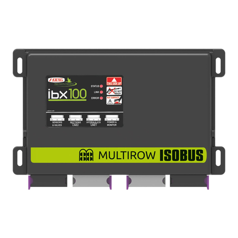
ECU =IBX100 remote control unit
This manual is an integral part of the equipment to which it refers and must accompany the equipment in case of sale or change of ownership. Keep it for any future
reference; ARAG reserves the right to modify product specifications and instructions at any moment and without notice.
LEGEND OF SYMBOLS
CONTENTS
1 Risks and protections..............................................................3
2 Product description..................................................................3
3 Intended use .............................................................................3
4 Precautions...............................................................................3
5 Package content.......................................................................4
6 Position on farming machine ..................................................4
6.1 System typical composition .............................................4
6.2 VISIO BLC .......................................................................5
6.3 IBX100 hydraulic control unit fixing..................................5
7 Installation of ultrasonic sensors ...........................................6
7.1 Sensor correct identification and positioning ...................7
7.2 Sensor optimal orientation...............................................8
8 Wiring connections ..................................................................9
8.1 General precautions for a correct harness position.........9
8.2 Power supply connection.................................................9
8.3 Wiring harness connection ............................................10
8.4 Visio BLC / IBX100 hydraulic unit connection................10
8.5 Ultrasonic sensors connection (boom leveling) .............10
8.6 Connection to pre-existing hydraulic control panel........10
8.7 Hydraulic valve connection............................................10
9 Accessories ............................................................................11
9.1 Pendrive.........................................................................11
10 Setting .....................................................................................12
10.1 Tests and checks before setting ....................................12
10.2 Controls in the menu......................................................12
10.3 Automatic detection upon system switching on.............12
11 Menu structure........................................................................13
12 Setup menu.............................................................................14
12.1 BLC settings ..................................................................14
12.1.1 Basic settings - WIZARD .................................................... 15
12.1.2 Boom settings..................................................................... 17
12.1.3 Adjustment parameters ...................................................... 17
12.1.4 Funct. Definition.................................................................. 20
12.1.5 IBX Properties .................................................................... 20
12.2 Options ..........................................................................21
12.2.1 Language............................................................................ 21
12.2.2 Unit of measurement .......................................................... 21
12.2.3 Display contrast .................................................................. 21
12.2.4 Alarm tones ........................................................................ 21
12.2.5 Keytones............................................................................. 21
12.2.6 User access........................................................................ 22
12.2.7 Operating mode.................................................................. 22
12.3 Setup management .......................................................23
12.3.1 Save VISIO setup - SETUP.BIN ......................................... 23
12.3.2 Load VISIO setup - SETUP.BIN.......................................... 23
12.3.3 Save IBX setup - CFGLEVEL.DAT..................................... 23
12.3.4 Load IBX setup - CFGLEVEL.DAT ..................................... 23
12.4 Test ................................................................................24
12.4.1 Display................................................................................ 24
12.4.2 Keys.................................................................................... 24
12.4.3 Sensors .............................................................................. 24
12.5 IBX100 Hydraulic Update ..............................................25
12.6 Factory default...............................................................25
12.6.1 VISIO restore...................................................................... 25
12.6.2 IBX restore of 100 Hydraulic............................................... 25
13 Preliminary setup for use ......................................................26
13.1 Quick settings ................................................................26
14 BLC control - how it works....................................................27
14.1 Fixed geometry..............................................................27
14.2 Hydraulic control............................................................27
15 Use...........................................................................................28
15.1 Start-up..........................................................................28
15.2 AUTOMATIC and MANUAL mode.................................28
15.3 Automatic control A........................................................29
15.4 Semi-automatic mode....................................................29
15.5 Manual control M............................................................29
16 Maintenance / diagnostics / repairs......................................30
16.1 Error messages .............................................................30
16.2 Troubleshooting .............................................................30
16.3 Data and units of measurement shown - Setup menu...30
17 Technical data.........................................................................31
18 End-of-life disposal ................................................................31
19 Guarantee terms.....................................................................31
20 EU declaration of conformity ................................................31
3
INTRODUCTION
• MANUAL USE MODES
The section of this manual dedicated to the installation contains information for installers. For this reason we have used technical terms without
providing explanations which would be necessary for end users only.
THE INSTALLATION MUST BE CARRIED OUT BY AUTHORIZED AND SKILLED PERSONNEL ONLY. ARAG IS NOT RESPONSIBLE
FOR ANY OPERATION SPECIFIED IN THIS MANUAL CARRIED OUT BY UNAUTHORIZED OR UNSKILLED PERSONNEL.
• RESPONSIBILITY
The installer must carry out "workmanlike" installations and ensure to the end user the perfect operation of the whole system both with ARAG
components only and other brands' components.
ARAG always recommends using its components to install control systems.
The installer will be held responsible for any malfunction if he decides to use other brands' components even without actually changing the system
parts or harness.
The compatibility check with components and accessories of other manufacturers shall be carried out by the installer.
If the ARAG components installed together with other brands' components get damaged because of what stated above, no direct or indirect
warranty will be provided.
1 RISKS AND PROTECTIONS
All installation works must be done with battery disconnected, using suitable tools and any individual protection equipment
deemed necessary.
Use ONLY clean water for treatment tests and simulations: using chemicals during simulated treatment runs can seriously
injure persons in the vicinity.
DO NOT WORK NEAR THE BOOM WHILE THE BLC CONTROL SYSTEM IS IN OPERATION.
2 PRODUCT DESCRIPTION
BLC Visio is the stand alone system for boom leveling control (BLC) that allows keeping the sprayer arm parallel to the field orientation and managing
its distance from the ground through the dedicated control unit - IBX100 hydraulic control unit- so as to ensure an even spraying covering.
The IBX100 hydraulic unit supplied with the BLC kit is already active for use.
A new activation code is NECESSARY ONLY with the purchase of a spare control unit (activation procedure on page20).
3 INTENDED USE
The equipment is designed and built to work on agricultural machinery for spraying and crop spraying applications on golf
courses, in compliance with EN ISO 14982 standard (Electromagnetic compatibility - Forestry and farming machines, for green
spaces and gardens) harmonized with Directive 2014/30/EU.
4 PRECAUTIONS
• Do not aim water jets at the equipment.
• Do not use solvents or fuel to clean the case outer surface.
• Do not clean equipment with direct water jets.
• Comply with the specified power voltage (12 VDC).
• In case of voltaic arc welding, remove connectors from the device and disconnect the power cables.
• Only use ARAG genuine spare parts and accessories.

4
INSTALLATION
5 PACKAGE CONTENT
Fig. 1
1 Visio BLC
2 IBX100 hydraulic control unit
3 Ultrasonic sensors (no. 2)
4 Connection cables (ref. par.6.1 System typical composition):
• Extension for sensors - 5 m (no. 2)
• Adapter cables for ultrasonic sensors (no. 2)
• Connection cable for sensors
• Cable for the connection of IBX100 hydraulic unit / power supply / BLC Visio
• Cable for the connection of BLC Visio / power supply / IBX100 hydraulic unit
• Connection cable to pre-existing hydraulic control panel
• Hydraulic valve connection cable for boom leveling
5 Fixing kit
The kit supplied enables the BLC control function on an already existing
system: therefore, the mechanical and hydraulic components are supplied by
the machine manufacturer.
The hydraulic valves for boom leveling must be purchased separately.
6 POSITION ON FARMING MACHINE
6.1 System typical composition
1
3
6
5
4
9 11
12
2
10
7
8
Fig. 2
Legend:
1 Visio BLC
2 IBX100 hydraulic control unit
3 Cable for the connection of BLC Visio / power supply / IBX100 hydraulic unit
4 Cable for the connection of IBX100 hydraulic unit / power supply / BLC Visio
5 Connection cable for sensors (boom leveling)
6 Extension for sensors - 5 m (no. 2)
7 Adapter cables for ultrasonic sensors (no. 2)
8 Ultrasonic sensors (no. 2)
9 Connection cable to pre-existing hydraulic control panel
10 Preexisting hydraulic control panel (not supplied)
11 Hydraulic valve connection cable for boom leveling
12 Hydraulic assembly (not supplied)

5
INSTALLATION
Fig. 3 Fig. 4
1Set mounting rail in cabin and fasten it with the relevant screws (Fig. 4), in a position where VISIO can be easily seen and at hands' reach, but
away from any moving organs.
2Secure VISIO to rail and push down until locked in place.
3Fasten harnesses so that they do not interfere with any moving parts.
6.2 VISIO BLC
6.3 IBX100 hydraulic control unit fixing
Secure the control unit on the back of the machine, close to the hydraulic unit.
Consider all necessary connections of the device (par. 6.1), the cable length, and make sure there is enough space for
connectors and cables. For any reference to the system configuration read par. 6.1.
Respect the mounting direction of the control units, as specified in Fig. 5 (connectors shall be facing down).
Fix the IBX100 using the 4 bolts fitted into their slots (A, Fig. 5).
No other type of assembly is allowed.
Fig. 5
Fig. 6

6
INSTALLATION
Crop
7 INSTALLATION OF ULTRASONIC SENSORS
It is the installer responsibility to check that all indications described are complied with.
The images relevant to sensors are purely indicative.
Precautions to follow for a long-lasting installation:
• Fix the sensor to a strong structure.
• Protect sensor body and connector with a guard.
• Keep sensor sensitive surface clean.
• Clean only with a soft wet cloth.
• Do not use aggressive detergents or products.
• Do not clean equipment with direct water jets.
Fig. 7
Yellow LED Yellow LED Green LED
Green
LED
CONNECTOR
Not connected
+ 12 V
GND
PIN
M12x1, 5-pin
Not connected
Analogue output
POSITION COLOR CONNECTION
1Brown + 12 V
2-- Not connected
3Blue GND
4Black Analogue output
5-- Not connected
Fig. 8
Travel direction
(FORWARD)
INSTALLATION ORIENTATION
Connector
Sensitive flat
surface
Fixing holes
For a correct operation, respect the installation direction (Fig. 8).

7
INSTALLATION
7.1 Sensor correct identification and positioning
Two types of layouts are available:
• BASIC SETUP - with a pair of sensors US1 + US2 (Fig. 9).
Fig. 9
Place the sensors in relation to the boom center CC:
US1 (LH side) + US2 (RH side) = external pair of sensors (far from boom center), at a distance from boom end corresponding
approximately to 30% of the half-boom length.
• COMPLETE SETUP - with two pairs of sensors US1 + US2 and US3 + US4 (Fig. 10).
Fig. 10
Place the sensors in relation to the boom center CC:
US1 (LH side) + US2 (RH side) = external pair of sensors (far from boom center) refer to basic setup.
US3 + US4 = internal pair of sensors (the ones closest to boom center), at a distance from boom center corresponding to
approximately 30% of the half-boom length.
Install the US1 / US3 sensors on the LH side of the boom and the US2 / US4 sensors on the RH side (rear view of the tractor).
The configuration with two pairs of sensors is to be preferred: in case of very large booms, it allows creating an average of the
distances of sensors from ground unevennesses.
Furthermore, the sensitive surface of the sensors must be positioned ALWAYS HIGHER than nozzle outlet (LV > 0 mm, Fig. 11).
SENSOR SENSITIVESENSOR SENSITIVE
SURFACESURFACE
NOZZLE OUTLETNOZZLE OUTLET
Fig. 11
CHECK THAT SENSORS ARE CONNECTED TO THE CORRESPONDING CONNECTORS AS PER THE MARKING INDICATED IN
PAR. 8.3 WIRING HARNESS CONNECTION.
THE SYSTEM COULD NOT BE ACKNOWLEDGED OR BE ABLE TO OPERATE WITH DIFFERENT CONNECTIONS.

8
INSTALLATION
7.2 Sensor optimal orientation
Fig. 12
• Lateral inclination (internal)
The sensors must be oriented towards the nearest side of the tractor; an inclination
of 5° is recommended and useful to compensate the gradient of the boom due to
the BLC system correction.
Fig. 13
• Forward inclination / height
As the ultrasound emission of the sensor has a conical shape with an amplitude of
approx. 15°, advance the sensors by 15° with respect to the tractor travel direction.
This inclination allows avoiding interferences with the cone outlet of the liquid
sprayed by the nozzles.
To optimize the sensor measuring capacity it might be also useful to move the
sensor position forward (always in relation to the travel direction) and / or increase
their height with respect to the nozzle outlet.
ALWAYS avoid the range of action of the sensor to superimpose the
spraying cone.
Fig. 14
• Minimum distance between the sensors
If the sensors are too close to one another ultrasound superimpositions may occur
causing system errors: respect the minimum distance of 2500 mm.
MIN.
25O mm
Fig. 15
• Minimum distance between the sensor and the ground
Position the sensor at a height such as to have a minimum distance of 250 mm
from the ground, in all possible working conditions.
A distance smaller than this threshold does not allow the correct operation of
the sensor, causing a wrong height measurement and possible unforeseen
movements.
It is the installer responsibility to check that the measurements detected by the sensors are correct and to avoid possible
interferences with the cone outlet of the liquid sprayed by the nozzles.

9
INSTALLATION
8 WIRING CONNECTIONS
• Use original ARAG harnesses only.
• Take care not to break, pull, tear or cut the cables.
• Use of unsuitable cables not provided by ARAG automatically voids the warranty.
• ARAG is not liable for any damage to the equipment, persons or animals caused by failure to observe the above instructions.
8.1 General precautions for a correct harness position
• Securing the cables:
- secure the harness so that it does not interfere with moving parts;
- route the harnesses so that they cannot be damaged or broken by machine movements or twisting.
• Routing the cables to protect against water infiltrations:
- the cable branches must ALWAYS be facing down.
• Fitting the cables to the connection points:
- Do not force the connectors by pushing too hard or bending them: the contacts may be damaged and system operation may be compromised.
Use ONLY the cables and accessories indicated in the catalog, having technical features suitable for the use to be made of them.
8.2 Power supply connection
WARNING:
TO AVOID SHORT CIRCUITS, DO NOT CONNECT THE POWER CABLES TO BATTERY BEFORE THE INSTALLATION IS COMPLETED.
BEFORE POWERING UP THE COMPUTER, MAKE SURE THE TRACTOR BATTERY VOLTAGE IS AS SPECIFIED (12 VDC).
The power source must be connected as indicated in Fig. 16:
IF ARC WELDING IS NEEDED, MAKE SURE THAT
THE DEVICE POWER SUPPLY IS DISCONNECTED; IF
NECESSARY DISCONNECT POWER CABLES.
Fig. 16
WIRE COLOR
(POWER CABLE) CONNECTION
Red Positive
Black Negative
Connect the power cable directly to the battery using the suitable eyelets.
WARNING! DO NOT connect to key-operated switch (15/54).

10
INSTALLATION
CONNECTOR CONNECTION
US1 ÷ US4 Ultrasonic sensor 1 ÷ 4
US5 NOT CONNECTED
AUX NOT CONNECTED
REF. CABLE 5 - par. 6.1
Close the unused connectors with the relevant caps supplied in the package.
CONNECTOR MOVEMENT CONTROL
DD Pilot valve
AA Opening Boom height:
UP
AC Closing Boom height:
DOWN
CA Opening
Boom leveling:
COUNTER-
CLOCKWISE
CC Closing Boom leveling:
CLOCKWISE
REF. CABLE 11 - par. 6.1
Fix the connectors to the relevant valves according
to the indicated initials.
• Position seal (1) onto connector (2), then connect
the latter pressing it fully home (3):
during this operation, take special care not to
bend valve electric contacts.
• Insert screw inside connector, and screw it (4)
until it is tightened.
CONNECTOR CONTROL
DD Pilot valve
AA Boom height - UP
AC Boom height - DOWN
CA Boom leveling - COUNTER-CLOCKWISE
CC Boom leveling - CLOCKWISE
REF. CABLE 9 - par. 6.1
This cable is used to receive the manual controls of the pre-existing control panel (e.g.
hydraulic control box).
IBX100 will control the suitable hydraulic valves based on the received manual controls or
based on the automatic control system.
When the BLC control operates in AUTOMATIC mode, the pre-existing hydraulic unit will
always have the priority on the IBX100 hydraulic control.
External control for headland detection
CLOSED CONTACT: HEIGHT HH (par. 15.3)
OPEN CONTACT: HEIGHT HS
REF. CABLE 4
par. 6.1
REF. CABLE 3 par. 6.1
CAN TERMINATION
IBX100
VISIO
8.3 Wiring harness connection
IBX100HYDRAULICUNIT
Fig. 17
CONNECTOR CONNECTION REF. CABLE
12 V Power supply
3 - par. 6.1
SIGNAL IBX100 hydraulic unit
VISIO BLC
Fig. 18
Connect harnesses as specified in the
table; each one of them shall be connected
to the corresponding socket on the remote
control unit.
NO. CONNECTION REF. CABLE - par.
6.1
1Ultrasonic sensors (boom leveling) 5
2Pre-existing hydraulic control panel 9
3Hydraulic unit 11
4Visio BLC / Power supply 4
8.4 Visio BLC / IBX100 hydraulic unit connection
8.5 Ultrasonic sensors connection (boom leveling)
8.6 Connection to pre-existing hydraulic control panel
8.7 Hydraulic valve connection

11
INSTALLATION
Fig. 19
9 ACCESSORIES
9.1 Pendrive
The pendrive may be used to exchange data with the BLC VISIO and IBX100.
Before use, format the SD board in FAT 32 mode; make sure that the board is not protected and can be read by the system. Most
pendrives with up to 2 Gb memory are compatible.

12
SETTING
- Access the selected menu
- Confirm changes and go back to previous menu
- Go back to previous menu
- Quit without confirming the changes
Pressed in sequence:
- Scroll the pages of a menu
- Change a value (increase)
Move the cursor during a change (press a
few times)
PROGRAMMING KEYSPROGRAMMING KEYS
10 SETTING
10.1 Tests and checks before setting
Before setup, check:
• that all components are correctly installed;
• the correct connection to the power source;
• the component connection.
Failure to correctly connect system components or to use specified components might damage the device or its components.
10.2 Controls in the menu
Fig. 20
SWITCHING ON
APress the key for 1 second.
BPress the key to view the various values in extended mode, in a sequence (on display central part).
Every time the device is switched on, it will shortly show a page with the name of device and
software version.
SWITCHING OFF
APress the key for 2 seconds.
Fig. 21
Setup menu
BLC settings
...
Options
Setup management
SELECTION AND ACCESS TO MENU ITEMS
APress a few times to scroll through items (selected item is indicated by a black line)
BPress to open the selected menu item
The three dots under an item indicate presence of another setup menu.
Fig. 22
Boom width
Min value 0.01
Max value 1000.00
EDITING A VALUE
APress to move through digits
BPress a few times to edit the highlighted digit
CPress to confirm modification. The display goes back to previous page.
DPress to exit page without confirming modification.
Edited value must fall within the range shown.
10.3 Automatic detection upon system switching on
Fig. 23
WARNING (IBX FW)!
V3.6.0 WRONG!
Update IBX to V4.3.x
[OK] Continue
Upon switching on, Visio checks the compatibility of the connected hydraulic control unit (IBX100).
• Obsolete firmware version (example at the side): the control unit must be updated, the system inhibits
the use of the device and allows only the update and switching off functions.
Contact the service center for the update.
• Hardware not compatible: the IBX100 control unit is not compatible with the BLC application.

13
SETTING
- Access the selected menu
- Confirm changes and go back to previous menu
- Go back to previous menu
- Quit without confirming the changes
Pressed in sequence:
- Scroll the pages of a menu
- Change a value (increase)
Move the cursor during a change (press a
few times)
PROGRAMMING KEYSPROGRAMMING KEYS
11 MENU STRUCTURE
For a correct use of the keys during setting, refer to par. 10.2.
SETUP MENU
SETTINGS
BLC settings
Basic settings
Start procedure
Number of sensors
External sens. [X]
External sens. [Y]
Internal sens. [X]
Internal sens. [Y]
HL Button
Boom settings
Boom geometry
Actuators
Boom width
Parameters adjust.
Height ctrl aggr.
Tilt. ctrl aggress.
Height error gain
Tilt. speed damping
Funct. Definition Headland detection
IBX Properties
Device name
Hardware version
Firmware version
Serial number
Activation code
OPTIONS
Language Česky - Deutsch - English - Español - Français - Magyar
Italiano - Polski - Português - Русский
Unit of measurement
Speed m/s
ft/s
Length m
ft
Height cm
in
Angle °
rad
Display contrast
Alarm tones
Keytones
User access
Operator
Manager
Technician
ARAGTech
Operating mode
Operating mode:
Only BLC
Only TTC
BLC and TTC
Boom geometry:
Fixed
Golf sprayer
Multi-row sprayer
SETUP MANAGEMENT
Save VISIO setup
Load VISIO setup
Save IBX setup
Load IBX setup
TEST
Firmware version
Hardware version
Battery voltage
Display
Keys
Sensors
IBX UPDATE
FACTORY DEFAULT VISIO restore
IBX restore

14
SETTING
- Access the selected menu
- Confirm changes and go back to previous menu
- Go back to previous menu
- Quit without confirming the changes
Pressed in sequence:
- Scroll the pages of a menu
- Change a value (increase)
Move the cursor during a change (press a
few times)
PROGRAMMING KEYSPROGRAMMING KEYS
12 SETUP MENU
Fig. 24
From the main page, press keys at the same time for 2 seconds to access.
12.1 BLC settings
This menu allows entering the mechanical characteristics of the spraying boom and the headland detection mode.
Fig. 25
Setup menu
BLC settings
...
Options
Setup management
Access the Setup menu.
Press to access the BLC settings menu.

15
SETTING
- Access the selected menu
- Confirm changes and go back to previous menu
- Go back to previous menu
- Quit without confirming the changes
Pressed in sequence:
- Scroll the pages of a menu
- Change a value (increase)
Move the cursor during a change (press a
few times)
PROGRAMMING KEYSPROGRAMMING KEYS
12.1.1 Basic settings - WIZARD
Fig. 26
BLC settings
Basic settings
...
Boom settings
Parameters adjust.
1
Basic settings
Start procedure...
Status: OK!
Number of sensors
External sens. [X]
2
Access the BLC settings menu.
1Press to access the Basic settings
menu.
2Press OK to start the wizard.
VISIO will guide you during the
configuration: follow the steps and select
the desired options. OK = Next step.
You can view the set values by scrolling the items of the Basic settings menu. Use of the keys at the bottom of the page.
SYSTEM WITH 2 SENSORS
Fig. 27
• Number of sensors: 2(US1 + US2). Number of ultrasonic sensors used by the BLC control.
• External sens. [X]: value relating to US1 + US2 (pair of external sensors).
BOOMBOOM
CENTERCENTER
ULTRASONICULTRASONIC
SENSORSENSOR
Fig. 28
Horizontal distance LH1 between the longitudinal axis of EXTERNAL sensors and boom center (Fig. 28).
Enter the value in the corresponding menu only once:
it is identical for the same pair of sensors.
• External sens. [Y]: value relating to US1 + US2 (pair of external sensors).
SENSOR SENSITIVESENSOR SENSITIVE
SURFACESURFACE
NOZZLE OUTLETNOZZLE OUTLET
Fig. 29
Vertical distance LV1 between the sensitive surface of EXTERNAL sensors and nozzle outlet (Fig. 29).
The sensitive surface must be positioned ALWAYS HIGHER than the outlet (LV > 0 mm).
Enter the value in the corresponding menu only once:
it is identical for the same pair of sensors.
• HL Button: select the device that will give the headland control HL.
External (external switch) or Keyboard (Visio keyboard, key ).
CONTINUES > > >

16
SETTING
- Access the selected menu
- Confirm changes and go back to previous menu
- Go back to previous menu
- Quit without confirming the changes
Pressed in sequence:
- Scroll the pages of a menu
- Change a value (increase)
Move the cursor during a change (press a
few times)
PROGRAMMING KEYSPROGRAMMING KEYS
SYSTEM WITH 4 SENSORS
Fig. 30
• Number of sensors: 4(US1 + US2 and US3 + US4). Number of ultrasonic sensors used by the BLC control.
• External sens. [X]: value relating to US1 + US2 (pair of external sensors).
BOOMBOOM
CENTERCENTER
ULTRASONICULTRASONIC
SENSORSENSOR
Fig. 31
Horizontal distance LH1 between the longitudinal axis of EXTERNAL sensors and boom center (Fig. 31).
Enter the value in the corresponding menu only once:
it is identical for the same pair of sensors.
• External sens. [Y]: value relating to US1 + US2 (pair of external sensors).
SENSOR SENSITIVESENSOR SENSITIVE
SURFACESURFACE
NOZZLE OUTLETNOZZLE OUTLET
Fig. 32
Vertical distance LV1 between the sensitive surface of EXTERNAL sensors and nozzle outlet (Fig. 32).
The sensitive surface must be positioned ALWAYS HIGHER than the outlet (LV > 0 mm).
Enter the value in the corresponding menu only once:
it is identical for the same pair of sensors.
• Internal sens. [X]: value relating to US3 + US4 (pair of internal sensors).
BOOMBOOM
CENTERCENTER
ULTRASONICULTRASONIC
SENSORSENSOR
Fig. 33
Horizontal distance LH2 between the longitudinal axis of INTERNAL sensors and boom center (Fig. 33).
Enter the value in the corresponding menu only once:
it is identical for the same pair of sensors.
• Internal sens. [Y]: value relating to US3 + US4 (pair of internal sensors).
SENSOR SENSITIVESENSOR SENSITIVE
SURFACESURFACE
NOZZLE OUTLETNOZZLE OUTLET
Fig. 34
Vertical distance LV2 between the sensitive surface of INTERNAL sensors and nozzle outlet (Fig. 34). The
sensitive surface must be positioned ALWAYS HIGHER than the outlet (LV > 0 mm).
Enter the value in the corresponding menu only once:
it is identical for the same pair of sensors.
• HL Button: select the device that will give the headland control HL.
External (external switch) or Keyboard (Visio keyboard, key ).

17
SETTING
- Access the selected menu
- Confirm changes and go back to previous menu
- Go back to previous menu
- Quit without confirming the changes
Pressed in sequence:
- Scroll the pages of a menu
- Change a value (increase)
Move the cursor during a change (press a
few times)
PROGRAMMING KEYSPROGRAMMING KEYS
12.1.2 Boom settings
Fig. 35
Boom settings
Boom geometry
Fixed
Actuators
Boom width
Access the BLC settings > Boom settings menu.
To modify these settings, see Operating mode. par.12.2.7
The display will show the current setting below the selected item.
Use of the keys at the bottom of the page.
• Boom geometry
• Actuators READ ONLY ITEMS
• Width boom
12.1.3 Adjustment parameters
This menu allows entering the boom dynamic characteristics.
Fig. 36
Parameters adjust.
Height ctrl aggr.
10.0
Tilt. ctrl aggress.
Height error gain
Access the BLC settings > Parameters adjust. menu.
Press OK to edit the selected menu item.
The display will show the current setting below the selected item.
Use of the keys at the bottom of the page.
• Height ctrl aggr.: boom height control aggressiveness (page18).
• Tilt ctrl aggress.: boom leveling control aggressiveness (page18).
• Height error gain: proportional gain on boom height (page19).
• Tilt. speed damping: damping derived from the boom leveling speed (page19).
The values must be detected directly on the machine because strictly linked to the hydraulic / mechanical system of the machine.
All parameters are explained in detail in the following pages.
CONTINUES > > >

18
SETTING
- Access the selected menu
- Confirm changes and go back to previous menu
- Go back to previous menu
- Quit without confirming the changes
Pressed in sequence:
- Scroll the pages of a menu
- Change a value (increase)
Move the cursor during a change (press a
few times)
PROGRAMMING KEYSPROGRAMMING KEYS
> > > 12.1.3 Adjustment parameters
The values must be detected directly on the machine because strictly linked to the factory model.
DURING MEASURING PROCEDURES, MOVE THE BOOM ALONG THE MAXIMUM ALLOWABLE DISTANCE, COMPATIBLY WITH
THE MACHINE MECHANICAL CHARACTERISTICS AND DIMENSIONS.
Height ctrl aggr. - BOOM HEIGHT CONTROL AGGRESSIVENESS
Fig. 37
Height ctrl aggr.
050.0
Min value 0.00
Max value 100.00
Use of the keys at the bottom of the page.
It adjusts the power applied by the BLC control to lift / lower the boom.
The easiest way to adjust the aggressiveness value is to check for the presence of swingings during
boom movement - from maximum to minimum height.
Too high or too low values make the control unstable and cause vibrations; adjust the aggressiveness
value until reaching a smooth implement control without jerks.
Carry out this procedure with the BOOM COMPLETELY OPEN:
1Check that the boom is perfectly horizontal to the ground.
2 Set the spraying height to the minimum value (Spraying height. menu, par. 13.1).
3Bring the rotation speed of the power take-off to the typical operating value.
4Disable the BLC control: activate the MANUAL mode (par. 15.2).
5Set an aggressiveness value (Fig. 37).
6Bring the boom to the maximum height (activate the lifting switch on the pre-existing hydraulic control panel).
7Enable the BLC control: activate the AUTOMATIC mode (par. 15.2).
The boom will move automatically to reach the spraying height:
• If boom movement is too slow and with jerks, the aggressiveness level is too low.
Repeat the procedure from point 4, increasing the value.
• If the boom moves too quickly and swinging the aggressiveness level is too high.
As before, repeat the procedure from point 4, decreasing the value.
The ideal adjustment is obtained when boom movement is smooth, without jerks.
Tilt ctrl aggress. - BOOM LEVELING CONTROL AGGRESSIVENESS
Fig. 38
Tilt. ctrl aggress.
002.0
Min value 0.00
Max value 100.00
Use of the keys at the bottom of the page.
It adjusts the power applied by the BLC control to rotate the boom.
The easiest way to adjust the aggressiveness value is to check for swingings during boom rotation.
Too high or too low values make the control unstable and cause vibrations; adjust the aggressiveness
value until reaching a smooth implement control without jerks.
Carry out this procedure with the BOOM COMPLETELY OPEN:
1 Set the boom rotation center Cto maximum height.
2Bring the rotation speed of the power take-off to the typical operating value.
3Disable the BLC control: activate the MANUAL mode (par. 15.2).
4Set an aggressiveness value (Fig. 38).
5Bring the boom LH end to the minimum height (activate the lifting switch on the pre-existing hydraulic control panel).
6Enable the BLC control: activate the AUTOMATIC mode (par. 15.2).
The boom will rotate automatically to reach the horizontal position:
• If boom movement is too slow and with jerks, the aggressiveness level is too low.
Repeat the procedure from point 3, increasing the value.
• If the boom moves too quickly and swinging the aggressiveness level is too high.
As before, repeat the procedure from point 3, decreasing the value.
The ideal adjustment is obtained when boom movement is smooth, without jerks.
The Tilt ctrl aggress. parameter works in combination with the following Tilt speed damping on page19:
if aggressiveness setup is not as desired, increase the gain and repeat the adjustment.
CONTINUES > > >

19
SETTING
- Access the selected menu
- Confirm changes and go back to previous menu
- Go back to previous menu
- Quit without confirming the changes
Pressed in sequence:
- Scroll the pages of a menu
- Change a value (increase)
Move the cursor during a change (press a
few times)
PROGRAMMING KEYSPROGRAMMING KEYS
> > > 12.1.3 Adjustment parameters
The values must be detected directly on the machine because strictly linked to the factory model.
DURING MEASURING PROCEDURES, MOVE THE BOOM ALONG THE MAXIMUM ALLOWABLE DISTANCE, COMPATIBLY WITH
THE MACHINE MECHANICAL CHARACTERISTICS AND DIMENSIONS.
Gain height error - PROPORTIONAL GAIN ON BOOM HEIGHT CONTROL
Fig. 39
Height error gain
0100.0
Min value 0.0
Max value 9999.9
Use of the keys at the bottom of the page.
This parameter works in combination with the aggressiveness of the boom height control.
It reduces the error between the set spraying height and the one effectively reached with the BLC system.
Before entering the gain factor set the aggressiveness (Height ctrl aggr.menu on page18).
The easiest way to determine the value is to check the boom height after the BLC system has completed the correction; adjust the gain, if
necessary.
Carry out this procedure with the BOOM COMPLETELY OPEN:
1Check that the boom is perfectly horizontal to the ground.
2 Set the spraying height to the minimum value (Spraying height. menu, par. 13.1).
3Bring the rotation speed of the power take-off to the typical operating value.
4Disable the BLC control: activate the MANUAL mode (par. 15.2).
5Bring the boom to the maximum height (activate the lifting switch on the pre-existing hydraulic control panel).
6Set a gain value (Fig. 39).
7Enable the BLC control: activate the AUTOMATIC mode (par. 15.2).
The boom will move automatically to reach the spraying height.
Check the height reached:
• If the boom has exceeded the set height, repeat the procedure from point 4, decreasing the value.
• If the boom has not reached the set height, repeat the procedure from point 4, increasing the value.
Now, if the boom lifting control exceeds the set height, lower the aggressiveness and repeat the procedure relevant to the gain.
Tilt. speed damping - DAMPING ON BOOM ROTATION CONTROL
Fig. 40
Tilt. speed damping
0500.0
Min value 0.0
Max value 9999.9
Use of the keys at the bottom of the page.
This parameter works in combination with the aggressiveness of the boom leveling control.
It allows the BLC system to rotate the boom without swingings or position errors.
Before entering the damping factor, set the aggressiveness (Tilt ctrl aggress.menu on
page18):
if the setup of Tilt ctrl aggress. is not carried out properly, increase the gain value (Fig. 40).

20
SETTING
- Access the selected menu
- Confirm changes and go back to previous menu
- Go back to previous menu
- Quit without confirming the changes
Pressed in sequence:
- Scroll the pages of a menu
- Change a value (increase)
Move the cursor during a change (press a
few times)
PROGRAMMING KEYSPROGRAMMING KEYS
12.1.4 Funct. Definition
• Headland detection
It allows setting the control that communicates the headland area to the hydraulic control unit.
Operating details in par. 15.3 Automatic control A.
Fig. 41
Funct. Definition
Headland detection
HL Button
Access the BLC settings > Funct. Definition menu.
Press OK to edit the selected menu item.
The display will show the current setting below the selected item.
Use of the keys at the bottom of the page.
• HL Button: the headland control is provided by an external switch or by the Visio keyboard, based on setting made in par. 12.1.1.
• “Height” switch: the headland control is provided by the boom lifting switch.
• HL Button/Height: the headland control is provided both by the external switch / keyboard and by the pre-existing control panel.
• OFF: The IBX100 unit will perform ONLY the corrections required to keep the boom to the spraying height HS.
12.1.5 IBX Properties
It allows consulting the hardware and firmware information of the IBX100 hydraulic unit.
Fig. 42
IBX Properties
Device name
Hydraulic Arag
Hardware version
Firmware version
Access the BLC settings > IBX Properties menu.
Press the key on the side to scroll the items.
The display will show the current setting below the selected item.
Use of the keys at the bottom of the page.
• Device name.
• Hardware version. READ ONLY ITEMS
• Firmware version.
• Serial number.
• Activation code: Use this menu to activate a spare hydraulic control unit*.
* Usually, the hydraulic control unit supplied with the kit is already activated (par. 15.3 Automatic control A).
Fig. 43
Activation code
0000001234567890
[Arrow D] to delete
Access the IBX Properties > Activation code menu.
Hold the key on the side pressed to delete the old code:
release the key when all digits are zero.
Enter the new code.
Table of contents
Other ARAG Control Unit manuals

ARAG
ARAG IBX100 4679004 User manual

ARAG
ARAG IBX100 4679004 Quick start guide

ARAG
ARAG IBX100 4679004 Quick start guide

ARAG
ARAG 863T Series Quick start guide

ARAG
ARAG IBX100 4679004 Specification sheet

ARAG
ARAG 453 Series User guide

ARAG
ARAG IBX100 4679004 Installation and operating instructions

ARAG
ARAG 8537 Series Quick start guide

ARAG
ARAG 853 Series Quick start guide

ARAG
ARAG IBX100 4679004 Quick start guide