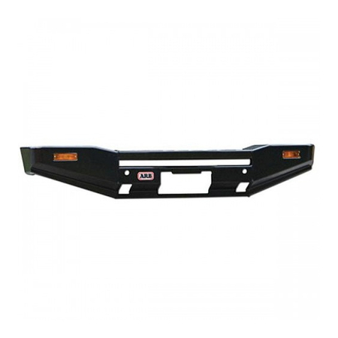
ARB 2237010 User manual

20/08/2014
Page 1 of 15
Fitting instructions# 3789248
Copyright © 2005 by ARB Corporation Limited. All rights reserved, this document must not be reproduced without the express authority of ARB Corporation Ltd
Part Number:
2237010-2237020-2237030
Product
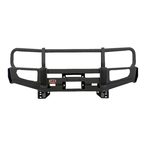
Description: Modular Bar
Suited to DODGE RAM 2500/3500 2012 on
vehicle/s:
WARNING
REGARDING VEHICLES EQUIPPED WITH SRS AIRBAG;
When installed in accordance with these instructions, the front protection bar does not affect operation
of the SRS airbag.
ALSO, NOTE THE FOLLOWING:
This product must be installed exactly as per these instructions using only the hardware
supplied.
In the event of damage to any bull bar component, contact your nearest authorised ARB
stockist. Repairs or modifications to the impact absorption system must not be attempted.
Do not use this product for any vehicle make or model, other than those specified by ARB.
Do not remove labels from this bull bar.
This product or its fixing must not be modified in any way.
The installation of this product may require the use of specialized tools and/or techniques
It is recommended that this product is only installed by trained personnel
These instructions are correct as at the publication date. ARB Corporation Ltd. cannot be held
responsible for the impact of any changes subsequently made by the vehicle manufacturer
During installation, it is the duty of the installer to check correct operation/clearances of all
components
Work safely at all times
Unless otherwise instructed, tighten fasteners to specified torque
ARB 4x4 ACCESSORIES
Corporate Head Office
42-44 Garden St Tel: +61 (3) 9761 6622
Kilsyth, Victoria Fax: +61 (3) 9761 6807
AUSTRALIA 3137
www.arb.com.au

20/08/2014
Page 2 of 15
Fitting instructions# 3789248
Copyright © 2005 by ARB Corporation Limited. All rights reserved, this document must not be reproduced without the express authority of ARB Corporation Ltd
GENERAL CARE AND
MAINTENANCE
By choosing an ARB Bar, you have bought a product that is one of the most sought after 4WD products
in the world. Your bar is a properly engineered, reliable, quality accessory that represents excellent
value. To keep your bar in original condition it is important to care and maintain it following these
recommendations:
Prior to exposure to the weather your bar should be treated to a Canuba based polish on all
exposed surfaces. It is recommended that this is performed on a six monthly basis or following
exposure to salt, mud, sand or other contaminants.
As part of any Pre Trip Preparation, or on an annual basis, it is recommended that a thorough visual
inspection of the bar is carried out, making sure that all bolts and other components are torqued to
the correct specification. Also check that all wiring sheaths, connectors, and fittings are free of
damage. Replace any components as necessary. This service can be performed by your local
authorized ARB Stockist.
FITTING REQUIREMENTS
REQUIRED TOOLS FOR FITMENT OF PRODUCT:
METRIC SOCKET SET
METRIC RING AND OPENEDED SOCKET SET
ELECTRIC DRILL 13MM CAPACITY
10MM DRILL BITS
RUST INHIBITING PAINT
PHILLIPS AND FLAT BLADE SCREW DRIVER
TAPE MEASURE
HYDRAULIC LIFTING PLATFORM OR
ANOTHER PERSON.
SHARP CHISEL AND PLASTIC CUTTING SAW
TORQUE WRENCH
HAVE AVAILABLE THESE SAFETY ITEMS WHEN FITTING PRODUCT:
Protective eyewear
Hearing protection
NOTE: ‘WARNING’ notes in the fitting procedure relate to OHS situations, where to avoid a
potentially hazardous situation it is suggested that protective safety gear be worn or a safe work
procedure be employed. If these notes and warnings are not heeded, injury may result.
FASTENER TORQUE SETTINGS:
SIZE
Torque Nm
Torque lbft
M6
9Nm
7lbft
M8
22Nm
16lbft
M10
44Nm
32lbft
M12
77Nm
57lbft
ARB INTENSITY LIGHTS, UP TO 900 SERIES ROUND OR 800 RECTANGULAR IPF DRIVING OR FOG
LAMPS SUIT THIS PRODUCT
BAR IS DESIGNED TO ACCOMMODATE WARN ZEON 12 AND WARN 16.5TI WINCHES

20/08/2014
Page 3 of 15
Fitting instructions# 3789248
Copyright © 2005 by ARB Corporation Limited. All rights reserved, this document must not be reproduced without the express authority of ARB Corporation Ltd
MODULAR BAR OPTIONS
OPTION 1: BAR
OPTION 2: BAR AND TOP FRAME
OPTION3 : BAR, TOP FRAME AND OUTER FRAMES

20/08/2014
Page 4 of 15
Fitting instructions# 3789248
Copyright © 2005 by ARB Corporation Limited. All rights reserved, this document must not be reproduced without the express authority of ARB Corporation Ltd
PARTS LISTING
APPLICATION
PART NO
QTY
DESCRIPTION
CENTRE PAN
ASSY
5237010
3314965
1
PAN ASSY DODGE RAM
3759359
2
BKT ASSY CHASSIS DODGE RAM
3752000
1
BRKT LICENSE
3759288
1
BRACKET FAIRLEAD MOUNT F TRUCK
3759363
1
BRACKET DEFLECTOR DODGE RAM
6522928
1
GRILLE ASSY DODGE RAM
6522951
1
PANEL COVER DODGE RAM
3194637
1
NUT PLATE ASSEMBLY DODGE RAM
3163073
2
BLANKING PLUG 12.7mm
3163091
4
BLANKING PLUG 17.4mm
EG50
2
RUBBER GROMMET
180302
4
CABLE TIES
5848409
2
PACKER CHASSIS DODGE RAM
5846401
8
WASHER FLAT M12 X 8MM
6151542
4
BOLT M10 X 40 SEMS
4584326
8
WASHER SPRING M12 BLACK
6151552
8
BOLT M12 X 60 BLACK
6151428
8
M12 X1.175 FLANGE NUT
6151357
11
BOLT M10 X 30 SEMS
6151321
11
NUT FLANGE M10X1.5
4584328
6
WASHER F M8 x 19 x 1.2
6151256
8
SCREW M6X16 BUTTON HEAD S/S
6151561
8
NUT FLANGE M6
6151546
6
BOLT HXHD M8 x 1.25 x 25 GR8.8
6151548
6
NUT FLANGE M8 x 1.25 GR8.8
6151184
2
M8x30 SHCS SS
4581094
2
WASHER SPRING M8 x 3/32 x 3/32 SS
4581081
2
WASHER FLAT, M8 SS
4581304
8
WASHER FLAT, M6 SS
WINGS
5137010
3131474R
1
WING ASSY DODGE RAM RIGHT
3131474L
1
WING ASSY DODGE RAM LEFT
3500590
1
FOG LIGHT KIT
4681485
1
BRACE WING RIGHT
4681485L
1
BRACE WING LEFT
4581011
10
WASHER FLAT, M12 x 27 x 4
6151480
10
NUT FLANGE M12 X 1.25 ZP
6151321
8
NUT FLANGE M10 x 1.5 ZP
6151357
8
BOLT SEMS M10 X 30 ZP Gd 8.8
3163073
2
PLUG BLANKING BLK 17.4mm
6151094
10
BOLT M12 x 1.25 x 30 Gd 8.8 ZP
4581040
8
WASHER FLAT, M10 x 25 x 3 ZP

20/08/2014
Page 5 of 15
Fitting instructions# 3789248
Copyright © 2005 by ARB Corporation Limited. All rights reserved, this document must not be reproduced without the express authority of ARB Corporation Ltd
PARTS LISTING cont.
TOP
FRAME
5137020
5665933
1
FRAME ASSY DODGE RAM
5665935
2
UPRIGHT END PANEL DODGE RAM
3759392
2
BKT ASSY CENTRE FRAME
4581094
24
WASHER SPRING M8 x 3/32 x 3/32 SS
4581081
24
WASHER FLAT, M8 SS
5811060
12
SLEEVE M8 THREAD F TRUCK
6151263
24
SCREW M8 X 1.25 X 20 S/S SHCS
6151671
4
SCREW M12x1.75x40 SHCS SS
4584354
4
WASHER FLAT M12 SS
4584355
4
WASHER SPRING M12 SS
OUTER
FARMES
5137030
6136367R
1
FRAME ASSY OUTER DODGE RAM RIGHT
6136367L
1
FRAME ASSY OUTER DODGE RAM LEFT
4581011
2
WASHER FLAT, M12 x 27 x 4
6151255
2
BOLT M12 x 1.75 x 40 Gd 8.8 ZP
4581064
2
WASHER SPRING M12 TZP480
VEHICLE PREPARATION
DEPENDING ON THE MODEL, THERE ARE TWO WAYS OF RETAINING
THE BUMPER.
Bumpers are mounted in 2 ways, Inward facing bolt plate that requires the removal of the
Intercooler and Outward facing bolt plate that needs notching out to allow pinning of the mounts to
the chassis in final steps.
Outward Bolt Plate requires
Cut out for pinning mounts
to chassis
BOLTS INWARDS
BOLTS OUTWARDS
Inward Bolt plate
Requires Intercooler
Removal

20/08/2014
Page 6 of 15
Fitting instructions# 3789248
Copyright © 2005 by ARB Corporation Limited. All rights reserved, this document must not be reproduced without the express authority of ARB Corporation Ltd
VEHICLE PREPARATION
1. Disconnect Battery terminal.
2. Remove the License plate and set aside.
3. Remove plastic plugs from radiator top cover.
4. Remove the 4 screws on top of grille and pull
the grille outwards to remove.
5. Disconnect the Fog light loom plug, from
behind the bumper.
6. Vehicles with Outward facing bolt plate,
proceed to step 13
7. Remove the Anti-Intrusion Brackets from both
sides of the chassis and set aside.
8. Undo the hose clamps to the intercooler, one
per side.
9. Remove the bolts from the Intercooler
retaining brackets, two per side. As shown
10. Remove the Intercooler assembly and set
aside.
11. Remove the plastic shroud from the
Intercooler.

20/08/2014
Page 7 of 15
Fitting instructions# 3789248
Copyright © 2005 by ARB Corporation Limited. All rights reserved, this document must not be reproduced without the express authority of ARB Corporation Ltd
12. Undo the Bumper retaining bolt plates as
described in step1 , on each side and with
assistance, remove the Bumper and set
aside.
13. Remove the Fog light loom from the Bumper
and set aside.
14. Remove the Tow Hooks and retain.
MAIN BUMPER INSTALLATION
15. Models with Outward facing bolt plate require
the bolt plate to be cut as shown, to later
access pinning bolt. Paint cut edge with rust
preventative paint.
16. Place the Bullbar mounts onto the chassis
and re insert the bolt plates in the same
direction as they were removed. Refer to step
1 for details.
17. Loosely fasten with the original nuts.
18. Insert the nut plates (1 per side) Note the
orientation of the plate to the chassis in photo
2 (shown without mounts for clarity). The nut
plate remains loose at this stage
Phot 1 shows bolt plate for inward facing
configuration.
60mm
20mm
1
2

20/08/2014
Page 8 of 15
Fitting instructions# 3789248
Copyright © 2005 by ARB Corporation Limited. All rights reserved, this document must not be reproduced without the express authority of ARB Corporation Ltd
19. Insert the chassis packers between the inner
Mount face and the outer chassis face
ensuring the packer slots over the mount
bolts. 1 per mount.
20. Ensure the mounts are as far forward as
possible and tighten the Mount bolts until the
packers are firm. Do not tighten to specified
torque at this stage.
BAR PREPARATION
21. If Installing a winch, fit the RFL bracket to the
bar using 4 M10 x 30 SEMS and flange
washers as shown.
22. Fit the Roller Fairlead to the Bracket using 2
M10 x 30 SEMS and flange nuts.
23. If Installing Warn 16.5TI , fasten the control
box to the RFL bracket using 2 M8x30 ss
bolts, spring washers and flat washers.
24. Load the winch onto the Bar and fasten from
underneath using the fasteners supplied with
the winch. Refer to winch manufactures
installation manual for wiring and fitment
connections.
For large frame Warn winches (including
16,500lb), tighten mounting bolts to 50-55 ft.
lbs (68-78 Nm).
For Warn Zeon winches, tighten mounting
bolts to 30-35 ft (41-47 Nm).

20/08/2014
Page 9 of 15
Fitting instructions# 3789248
Copyright © 2005 by ARB Corporation Limited. All rights reserved, this document must not be reproduced without the express authority of ARB Corporation Ltd
25. If fitting a Zeon 12 a portion of the grille will
need to be removed to accommodate the top
cap of the winch. Tape the lower centre
section of the grille.
26. Measure and mark the vertical centre line of
the grille and mark the cut out as per photo.
27. Trim with a suitable saw and de-bur the sharp
edges.
28. Re-fit the grille and if necessary trim more to
achieve at least 10mm clearance around the
top cap of the winch.
29. Insert the rubber grommets into the Centre
section, 1 per side.
BAR INSTALLATION
30. If removed at steps 8-11,Re-install the
Intercooler and anti- intrusion Brackets using
original fasteners.
31. With assistance, fasten the Centre Pan
Assembly to the Mounts using the
M12x60mm bolts, with spring washers
through the original tow hook then loosely
fasten behind the mount with M12 x 8mm
thick washers and original nuts. 4 per side.
32. From underneath, fasten the back of the
centre section to the Chassis mounts with 2
M10x30SEMS bolts and flange nuts.
33. Align the Centre assembly so as the top face
sits horizontal. Tighten all nuts to specified
torque.
NOTE: Ensure there is at least 20mm clearance
between the Bar and Radiators.
Front Face of Bar is designed to rake towards the
vehicle along lower edge.

20/08/2014
Page 10 of 15
Fitting instructions# 3789248
Copyright © 2005 by ARB Corporation Limited. All rights reserved, this document must not be reproduced without the express authority of ARB Corporation Ltd
34. If not installing a winch, place the grille panel
in from behind the bar and fasten with the 6
M8 bolts, washers and flange nuts.
35. Before fitting the wings to the centre section,
the vehicles fog light loom needs to be
modified to suit the ARB fog lights.
Using a sharp chisel, cut out rib from plug.
Place plug sideways on bench and slice out
the rib as shown.
ALLWAYS CUT AWAY FROM YOUR
HANDS
Check loom fits ARB Fog light plugs. If not
more will need to be trimmed from rib.
36. Insert the fog lights into the wing from the
front, locating into the three positions as
shown.

20/08/2014
Page 11 of 15
Fitting instructions# 3789248
Copyright © 2005 by ARB Corporation Limited. All rights reserved, this document must not be reproduced without the express authority of ARB Corporation Ltd
WING INSTALLATION
37. Using the M12x35 fine thread bolts,flat
washers, spring washers and flange nuts, bolt
the wing to the centre section aligning al the
front faces and tighten . 5 per side.
M12 - 77 Nm.
38. Fit the wing braces from the centre section to
the wing, using the M10 x 30mm SEMS and
Flange nuts. 4 per side.
39. Ensure there is a parallel gap between the
body and the top face of the wing of around
15mm. The chassis mounts may have to be
loosened to achieve this. Tighten all bolts to
specified torque.
40. Connect the Fog light loom to the vehicle
harness and closest fog light. Feed the loom
through the large rubber grommets and
connect to other fog light. Cable tie loom to
wing brace and centre section.
M10 - 44 Nm.

20/08/2014
Page 12 of 15
Fitting instructions# 3789248
Copyright © 2005 by ARB Corporation Limited. All rights reserved, this document must not be reproduced without the express authority of ARB Corporation Ltd
CENTRE SECTION INSTALLATION
41. At this stage tighten all fasteners to specified
torque.
42. Place the top section onto the Centre
assembly and locate using the M12 cap
screws, spring washers and flat washers.
43. With assistance locate the nut plate under the
centre section fasten the M12 bolts to the
plate.
44. Take the 12 threaded sleeves and the 24, M8
cap screws, spring and flat washers and from
the inner face secure one side of the
threaded sleeves to the upright face. 6 per
side
45. If outer frame are not being fitted, place the
end plates up against the threaded sleeves
and fasten with the remaining M8 hardware.
M8 - 24 Nm.

20/08/2014
Page 13 of 15
Fitting instructions# 3789248
Copyright © 2005 by ARB Corporation Limited. All rights reserved, this document must not be reproduced without the express authority of ARB Corporation Ltd
OUTEREFRAME INSTALLATION
46. If fitting the outer frames, loosely fasten the
upright flange to the threaded sleeve as in
above step.
47. Take the 2 M12 x 40mm bolts spring and flat
washers and from inside the wing fasten the
outer frame to the wing. Tighten to specified
torque.
48. Check that the Bar is aligned to the vehicle
and using a 10mm drill bit, drill through the 2
pinning holes through the outside face of the
chassis. Ensure the nut plate is clear of the
drill. Paint exposed areas with rust
preventative paint.
49. Take the M10 x 40 SEMS bolts and fasten to
the internal nut plate and tighten to specified
torque. 2 per side.
M10 - 44 Nm.
50. If no winch is fitted, secure license plate
directly to bar using M6 dome head stainless
steel screws, flange nuts and SS flat
washers.
51. For vehicle with winch, fit license plate
bracket shown. Also using M6 dome head
stainless steel screws, flange nuts and SS flat
washers.
52. If centre frame or outer frame kits were not
installed, place plastic plugs supplied through
the holes on top of bar.
M6 - 9 Nm.

20/08/2014
Page 14 of 15
Fitting instructions# 3789248
Copyright © 2005 by ARB Corporation Limited. All rights reserved, this document must not be reproduced without the express authority of ARB Corporation Ltd
53. For Non winch application, place the top
cover on top of Centre section and fasten with
4 M6 button head screws, flat washers and
flange nuts.
54. Using the 5 M10x30 SEMS bolts and flange
nuts, fit the lower deflector to the underside of
the lower pan to the lower holes in the anti -
intrusion bars.
55. Scribe a parallel line from the bottom of the
inner guard liner, just above the lower edge of
the wing.
56. Cut with a suitable saw and de-bur the edges.
57. Tuck the outer edge in behind the wing
flange.

20/08/2014
Page 15 of 15
Fitting instructions# 3789248
Copyright © 2005 by ARB Corporation Limited. All rights reserved, this document must not be reproduced without the express authority of ARB Corporation Ltd
FITTED PRODUCT
This manual suits for next models
2
Table of contents
Other ARB Automobile Accessories manuals
Popular Automobile Accessories manuals by other brands
Whispbar
Whispbar K582W Fitting instructions
Pavement Ends
Pavement Ends 41517 installation instructions
Roadmaster
Roadmaster 195125 Assembly and operating instructions

Pioneer
Pioneer HR 1500 PTO Installation, operation & maintenance manual

Flash Cover
Flash Cover MN017 installation manual
Metra Electronics
Metra Electronics 99-5027 installation instructions
