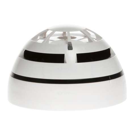
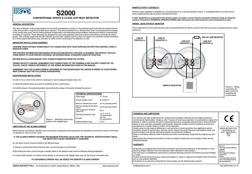
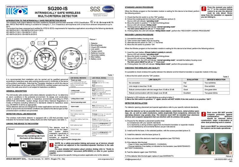
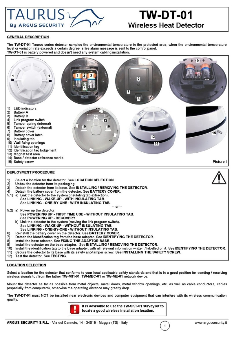
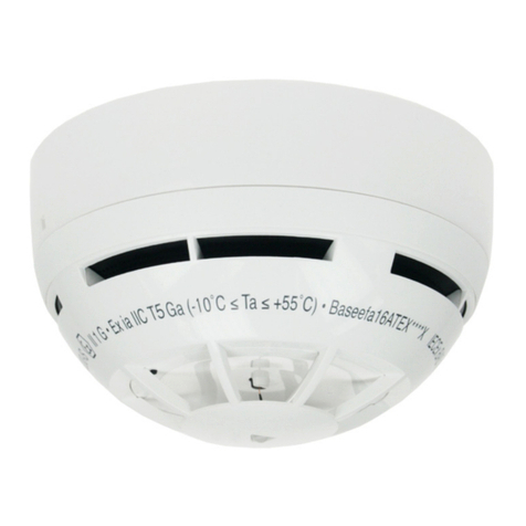
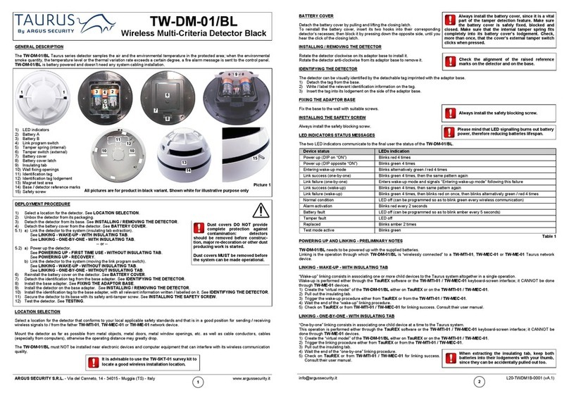
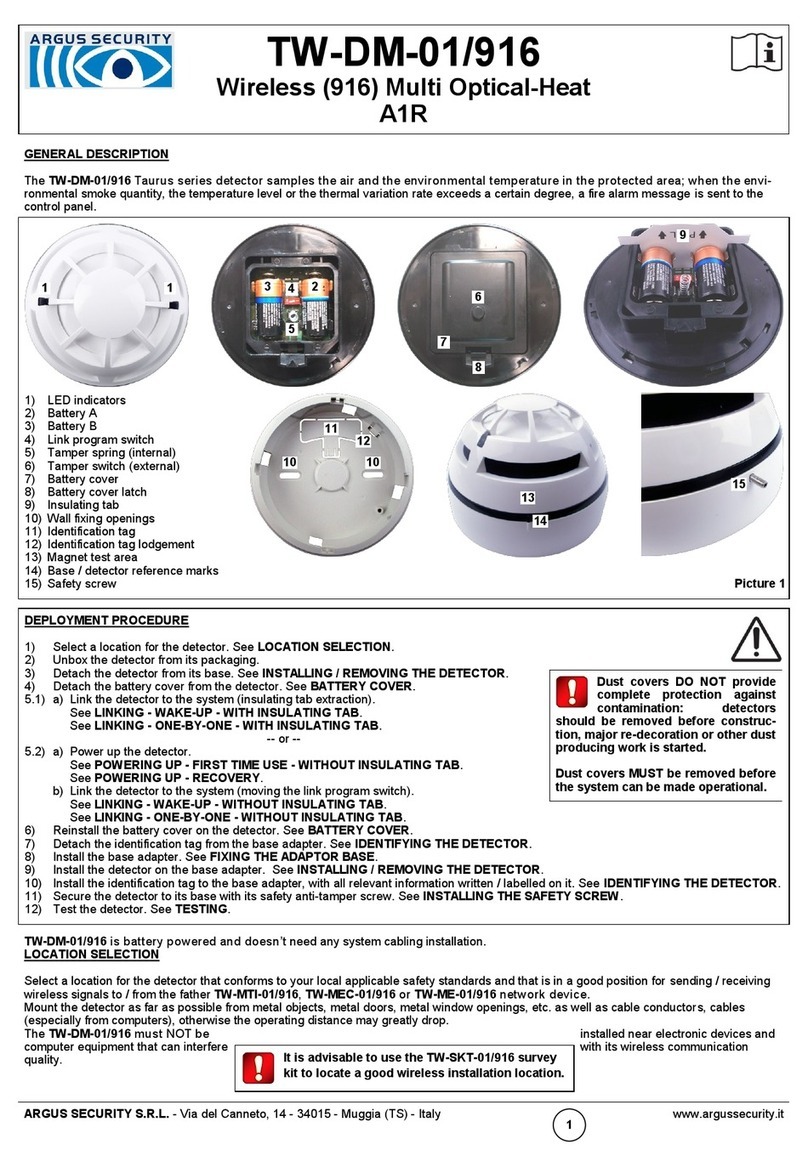
manuals.online logo
Brands
  1. Home
  2. •
  3. Brands
  4. •
  5. Argus Security
  6. •
  7. Security Sensor
  8. •
  9. Argus Security VCP100 User manual

Argus Security VCP100 User manual

VCP100
ANALOGUE RESETTABLE CALL POINT
INSTALLATION
The analogue call point must be used in combi-
nation with compatible control panels employing
the Vega communication protocol for monitoring
and control.
The location of call points should follow recog-
nised national or international application codes
of practice.
Connections to the terminals are polarity sensi-
tive: check them by referring to the wiring in-
structions contained in this manual.
CAUTION
Disconnect loop’s power before
installing the devices.
TECHNICAL SPECIFICATIONS
Power supply voltage range *from 18 Vdc to 40 Vdc
Average current consumption 70 uA
Operating temperature range from -20 °C to +65 °C
Humidity (no condensation) 95% RH
Dimensions (w/o back box) 87 x 87 x 23 mm
Maximum wire gauge 2.5 mm2
Picture 2 - using the provided drilling template - surface mounting
*Product operates down to 15 V, but without LED indication.
CAUTION
Electrostatic Sensitive Device.
Observe precautions when handling and making con-
nections.
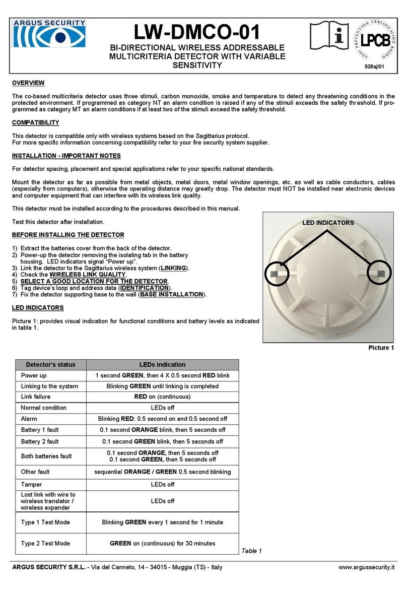
Picture 1 - wiring openings on the back box - surface mounting
Picture 3 - locations for screw insertion
on the back box - surface mounting
23 mm
87 mm
35 mm
87 mm
Front device
Activating front
window
Picture 5 - front device’s
dimensions
Picture 6 - supplied back
box’s dimensions
87 mm
+ IN
- IN + OUT
- OUT
Picture 7 - front device’s
wiring to the loop
Picture 4 - locations for screw insertion
on the installing frame - flush mounting
928h/01
ARGUS SECURITY S.R.L. - Via del Canneto, 14 - 34015 - Muggia (TS) - Italy www.argussecurity.it [email protected] SPNK-754431-080 (v2.2)
VCP100
PUNTO DI CHIAMATA ANALOGICO RIPRISTINABILE 928h/01
INSTALLLAZIONE
Il punto di chiamata analogico deve essere
utilizzato assieme a centrali compatibili che
fanno uso del protocollo di comunicazione Vega.
La locazione dei punti di chiamata deve essere
conforme a normative installative nazionali od
internazionali.
Le connessioni ai terminali sono sensibili alla
polarità: verificarle facendo riferimento alla
istruzioni di cablaggio contenute in questo
manuale.
ATTENZIONE
Disconnettere l’alimentazione del loop prima di
installare il sensore.
SPECIFICHE TECNICHE
Tensione di alimentazione * da 18 Vdc a 40 Vdc
Consumo medio di corrente 70 uA
Banda operativa di temperatura da -20 °C a +65 °C
Umidità massima (senza condensa) 95% RH
Dimensioni (senza base di montaggio) 87 x 87 x 23 mm
Massima sezione di filo compatibile 2.5 mm2
*Il prodotto opera fino a 15 V, ma senza indicazione del LED.
ATTENZIONE
Dispositivo sensibile alle scariche elettrostatiche.
Prendere adeguate precauzioni durante il suo maneggia-
mento e cablaggio.
Figura 2 - utilizzo della dima fornita per la trapanatura dei fori -
installazione su superficie
Figura 1 - aperture per i cavi sulla base di supporto - installazione su superficie
Figura 3 - fori per inserimento viti sulla base di supporto -
installazione su superficie
23 mm
87 mm
35 mm
87 mm
Dispositivo
frontale
Finestra
frontale di
attivazione
Figura 5 - dimensioni
del dispositivo frontale
Figura 6 - dimensioni della
base di supporto
87 mm
Figura 4 - fori per inserimento viti sulla corni-
ce di installazione - installazione complanare
+ IN
- IN + OUT
- OUT
Figura 7 - cablaggio al
loop analogico del dispo-
sitivo frontale
GENERAL DESCRIPTION
This product is a resettable fire emergency call point, compatible with the analogue-addressable Vega communication protocol.
This device gives the user, during its activation, the feel of breaking glass, nevertheless it maintains its integrity; after its activation,
the operating element can be simply restored with its supplied reset key.
An indicator drops into view at the top of the device’s front window after it has been pressed and activated; after the emergency has
been handled, the device is simply restored with its reset key and is ready for re-use straight away.
SHORT CIRCUIT ISOLATOR
All standard Vega series devices are provided with short-circuit monitoring isolators on the intelligent loop’s line and can be activated
by the control panel.
LED INDICATOR
This device is provided with a bicolour red / green LED (picture 12) meant to provide optical indication of the status of the device; this
indicator is controlled by the control panel.
ADDRESSING
The analogue call point can be addressed using a special hand-held programming unit or it can be auto-addressed by the control
panel after it has been installed (the implementation of the auto-addressing feature depends on the control panel’s manufacturer).
Addresses may be selected from a range from 1 to 240, although, of course, each device on the analogue loop must have a unique
address.
In order to address manually the analogue call point, connect it to the programming unit using the proper cable (refer to the program-
ming unit’s instruction manual).
INSTALLING THE DEVICE’S WALL SUPPORT
For specific information regarding detector and device’s spacing, placement and special applications refer to your specific national
standards.
In order to perform the installation, the front device must be securely installed on the wall. Two types of installations can be imple-
mented: surface mounting and flush mounting.
Surface mounting: in this case the supplied back box is used to fix the call point device to the wall.
Flush mounting: in this case a standard installing box is embedded into the wall: the supplied installing frame must be fixed to it.
1. Select the position of the analogue call point before installing and fixing it. Remember that this device is for indoor use only.
2. For surface mounting, feed the loop’s wires into the back box’s openings (picture 1) giving them a sufficient length; alternatively, 20
mm entry holes can be easily drilled on the sides of the back box by using the template provided on the top of the packaging box
(picture 2).
For flush mounting, feed the loop’s wires into the embedded standard installing box’s openings giving them a sufficient length.
3. For surface mounting, install and fix to the wall the device’s back box with the provided screws (picture 3).
For flush mounting, fix to the wall-embedded standard installing box the supplied frame with the provided screws (picture 4).
WIRING THE ANALOGUE CALL POINT
The analogue call point, as any other analogue device, must be connected to the analogue loop. Refer to picture 7 for wiring indica-
tions to the device’s terminal blocks.
DESCRIZIONE GENERALE
Questo prodotto è un punto di chiamata ripristinabile per le emergenze incendio, compatibile col protocollo di comunicazione analogi-
co Vega.
Questo dispositivo, quando attivato, dà la sensazione che il vetro frontale si stia rompendo, ciononostante la sua integrità viene
mantenuta; dopo l’attivazione l’elemento operativo può essere ripristinato semplicemente usando la chiave fornita assieme al prodot-
to.
Dopo che la finestra frontale è stata premuta ed il dispositivo attivato, comparirà un indicatore visivo sulla parte superiore della
finestra stessa; dopo che l’emergenza è stata risolta, il dispositivo può essere semplicemente ripristinato con la relativa chiave, ed il
dispositivo sarà pronto per un immediato riutilizzo.
ISOLATORI DI CORTO CIRCUITO
Tutti i dispositivi standard della serie Vega sono stati forniti con degli isolatori di monitoraggio di corti-circuito sulla linea analogica e
questi possono essere attivati da centrale.
INDICATORE LED
Questo dispositivo è equipaggiato con un LED bicolore rosso / verde (figura 12) che ha lo scopo di dare una indicazione visiva dello
stato del dispositivo; questo indicatore è controllato dalla centrale.
INDIRIZZAMENTO
Al punto di chiamata analogico può essere assegnato un indirizzo tramite uno speciale programmatore manuale o può essere asse-
gnato automaticamente dalla centrale dell’impianto successivamente all’installazione del dispositivo stesso.
La presenza o meno di questa funzione dipende esclusivamente dal tipo di centrale usata.
Gli indirizzi possono essere selezionati in un intervallo di valori da 1 a 240, anche se, ovviamente, ogni dispositivo su uno stesso
anello analogico deve avere un indirizzo univoco.
Allo scopo di assegnare manualmente un indirizzo al punto di chiamata, connettere il dispositivo al programmatore adoperando il
cavetto di interfaccia adatto (fare riferimento al manuale delle istruzioni del programmatore).
INSTALLAZIONE DEL SUPPORTO DA PARETE DEL DISPOSITIVO
Per informazioni specifiche riguardanti il posizionamento, distanziamento ed applicazioni particolari per i sensori ed i dispositivi
antincendio fare riferimento alle proprie normative nazionali.
Al fine di effettuare l’installazione, il dispositivo frontale deve essere installato saldamente a parete. Due tipi di installazione possono
essere effettuate: l’installazione su superficie e l’installazione complanare.
Installazione su superficie: in questo caso la base di supporto viene usata per fissare il dispositivo del punto di chiamata alla parete.
Installazione complanare: in questo caso una scatola elettrica di dimensioni standard ed adatte è inserita nella parete: ad essa va
fissata la cornice di installazione fornita assieme al prodotto.
1. Selezionare la posizione del punto di chiamata prima di installarlo e fissarlo. Ricordare che questo dispositivo è da usarsi solo
in interni.
2. Per l’installazione su superficie far scorrere i cavi del loop nelle aperture della scatola di supporto (figura 1) per una lunghezza
sufficiente; in alternativa, fori di 20 mm di diametro possono essere trapanati ai lati della scatola di supporto sfruttando l’ausilio della
dima fornita sul coperchio superiore della scatola di imballo del dispositivo (figura 2).
Per l’installazione complanare, far scorrere i cavi del loop nella scatola inserita nella parete per una lunghezza sufficiente.
3. Per l’installazione su superficie installare e fissare alla parete la base di supporto con le viti fornite (figura 3).
Per l’installazione complanare fissare la cornice alla scatola elettrica inserita nella parete utilizzando le viti fornite (figura 4).
CABLAGGIO DEL PUNTO DI CHIAMATA ANALOGICO
Questo punto di chiamata, come qualsiasi altro dispositivo analogico, deve essere connesso al loop. Fare riferimento alla figura 7 per
avere lo schema di cablaggio ai morsetti del dispositivo.
ACTIVATION
The analogue call point is activated
by pressing the transparent window
on the front of the device as shown in
picture 11.
HOW TO RESET
The analogue call point, after use, can
be re-armed using the provided key;
insert the key into the hole under the
device and rotate counter clockwise as
shown in picture 12.
Picture 8 - installing the front
device on the back box -
surface mounting
Picture 10 - removing the front device from
the back box - surface mounting, but the
same principle applies to flush mounting
LED
Picture 11
Picture 12
Picture 9 - installing the
front device on the installing
frame - flush mounting
0832
WARNINGS AND LIMITATIONS
Our devices use high quality electronic components and plastic materials that are highly resistant to
environmental deterioration. However, after 10 years of continuous operation, it is advisable to replace the
devices in order to minimize the risk of reduced performance caused by external factors. Ensure that
these devices are only used with compatible control panels. Detection systems must be checked, ser-
viced and maintained on a regular basis to confirm correct operation.
Smoke sensors may respond differently to various kinds of smoke particles, thus application advice
should be sought for special risks. Sensors cannot respond correctly if barriers exist between them and
the fire location and may be affected by special environmental conditions. Refer to and follow national
codes of practice and other internationally recognized fire engineering standards.
Appropriate risk assessment should be carried out initially to determine correct design criteria and updat-
ed periodically.
WARRANTY
All devices are supplied with the benefit of a limited 3 year warranty relating to faulty materials or manu-
facturing defects, effective from the production date indicated on each product. This warranty is invalidat-
ed by mechanical or electrical damage caused in the field by incorrect handling or usage. Product must
be returned via your authorized supplier for repair or replacement together with full information on any
problem identified.
Full details on our warranty and product’s returns policy can be obtained upon request.
ARGUS SECURITY S.R.L.
Via del Canneto, 14
34015 Muggia (TS)
Italy
09
0832-CPD-1059
EN 54-11
Manual call point
EN 54-17:2005
Short circuit isolator
VCP100
Technical data:
See document TDS-VCPXX
held by the manufacturer.
www.argussecurity.it
ARGUS SECURITY S.R.L. - Via del Canneto, 14 - 34015 - Muggia (TS) - Italy [email protected] SPNK-754431-080 (v2.2)
Figura 8 - installazione del
dispositivo frontale sulla
base di supporto - installazio-
ne su superficie
Figura 9 - installazione del
dispositivo frontale sulla
cornice di aggancio -
installazione complanare
Picture 10 - rimozione del dispositivo
frontale dalla base di supporto; la stessa
metodologia è valida anche per l’installa-
zione complanare
ATTIVAZIONE
Il punto di chiamata analogico viene
attivato premendo la finestra traspa-
rente frontale del dispositivo come
mostrato in figura 11.
RIPRISTINO
Il punto di chiamata analogico, dopo
essere stato utilizzato, può essere
riarmato tramite l’utilizzo della chiave
fornita; inserire la chiave nel foro sotto
il dispositivo e girarla in senso anti-
orario come mostrato in figura 12.
LED
Picture 11
Picture 12
0832
AVVERTENZE E LIMITAZIONI
I nostri dispositivi sono costruiti con componenti elettronici di alta qualità e materiali plastici molto resi-
stenti al deterioramento ambientale. Ciononostante, dopo 10 anni di operatività, si consiglia di sostituire i
dispositivi al fine di minimizzare il rischio di una ridotta prestazione derivata da fattori esterni. Ci si assicuri
che questo dispositivo sia usato soltanto con centrali compatibili. I sistemi di rilevamento devono essere
controllati e sottoposti regolarmente a manutenzione per ratificarne la corretta operatività.
I sensori di fumo possono rispondere differentemente a diversi tipi di particelle di fumo, quindi, per rischi
particolari, chiedere consulenza riguardo alla compatibilità di questo prodotto al proprio fornitore.
I sensori potrebbero non rispondere adeguatamente se tra gli stessi ed il luogo dell’incendio esistono
barriere; inoltre, particolari condizioni ambientali possono influire sulla loro risposta.
Fare riferimento ed applicare normative nazionali ed altri standard di sicurezza antincendio riconosciuti
internazionalmente.
Un’adeguata valutazione dei rischi dovrebbe essere effettuata inizialmente per definire i criteri di progetta-
zione ed aggiornata periodicamente.
GARANZIA
Tutti i dispositivi sono garantiti fino a 3 anni, limitatamente a materiali difettosi o difetti di fabbricazione, a
decorrere dalla data di produzione indicata su ogni prodotto.
Questa garanzia non copre danni meccanici od elettrici causati in campo da un uso scorretto ed inade-
guato.
Il prodotto deve essere ritornato, tramite il proprio fornitore, per riparazione o sostituzione, assieme ad
una descrizione completa di qualsiasi problema riscontrato. Tutti i dettegli sulla garanzia e sulla modalità
di ritorno dei prodotti possono essere ottenuti su richiesta.
ARGUS SECURITY S.R.L.
Via del Canneto, 14
34015 Muggia (TS)
Italy
09
0832-CPD-1059
EN 54-11
Manual call point
EN 54-17:2005
Short circuit isolator
VCP100
Dati tecnici: consultare il
documento TDS-VCPXX in
possesso del costruttore.
INSTALLING AND UNISTALLING THE FRONT DEVICE
In order to complete the installation, the front device must be securely installed on the wall-fixed back box or frame. In order to per-
form such task operate as illustrated in picture 8 for surface mounting or picture 9 for flush mounting.
To remove the front device from the supplied back box or frame use the two pins on the back of the reset key, insert them in the two
holes under the analogue call point, then push up until the front element is locked off (picture 10).
TESTING
In order to test the functionality of the installed analogue call point, the following test must be performed: activate an alarm condition
by pressing the call point’s front face window (see the ACTIVATION paragraph): a rectangular visual indicator will drop into view on
its upper left corner, an activation message will be sent to the control panel and the LED, piloted by the control panel, will soon
indicate such condition.
After each test the device must be reset (see the HOW TO RESET paragraph), so as the control panel.
All devices must be tested after installation and, successively, on a periodic basis.
INSTALLAZIONE E DISINSTALLAZIONE DEL DISPOSITIVO FRONTALE
Al fine di completare l’installazione, il dispositivo frontale deve essere agganciato sul relativo supporto fissato a parete oppure sulla
cornice; operare come illustrato in figura 8 per l’installazione su superficie o in figura 9 per l’installazione complanare.
Per rimuovere, invece, il dispositivo frontale dal supporto a parete o dalla cornice di aggancio fare uso dei due cilindretti in cima alla
chiave di ripristino, inserirli nei due fori sotto il punto di chiamata, spingere la chiave in alto fino allo sganciamento del blocco frontale
(figura 10).
COLLAUDO
Al fine di testare la funzionalità del punto di chiamata analogico installato, eseguire il seguente test: attivare una condizione di allarme
premendo la finestra frontale del dispositivo (vedere il paragrafo ATTIVAZIONE): un indicatore visivo rettangolare comparirà in
corrispondenza del lato sinistro superiore; un messaggio di attivazione verrà mandato alla centrale ed il LED, controllato dalla centra-
le stessa, indicherà presto tale condizione.
Dopo ogni test, il dispositivo deve essere ripristinato (vedere il paragrafo RIPRISTINO), così anche la centrale.
Tutti i dispositivi devono essere testati dopo l’installazione e, successivamente, periodicamente.

Other Argus Security Security Sensor manuals

Argus Security SG200 User manual

Argus Security

Argus Security SG200 User manual

Argus Security Taurus TW-DM-01 User manual

Argus Security

Argus Security Taurus TW-DM-01 User manual

Argus Security V100 User manual

Argus Security

Argus Security V100 User manual

Argus Security L-MC-SG User manual

Argus Security

Argus Security L-MC-SG User manual

Argus Security TAURUS TW-DT-01/BL User manual

Argus Security

Argus Security TAURUS TW-DT-01/BL User manual

Argus Security V200 User manual

Argus Security

Argus Security V200 User manual

Argus Security TAURUS TW-DT-01 User manual

Argus Security

Argus Security TAURUS TW-DT-01 User manual

Argus Security ALTAIR Series User manual

Argus Security

Argus Security ALTAIR Series User manual

Argus Security A2000L User manual

Argus Security

Argus Security A2000L User manual

Argus Security TAURUS TW-DM-01/BL User manual

Argus Security

Argus Security TAURUS TW-DM-01/BL User manual

Argus Security TW-DM-01/916 User manual

Argus Security

Argus Security TW-DM-01/916 User manual

Argus Security Taurus TW-DT-01/916 User manual

Argus Security

Argus Security Taurus TW-DT-01/916 User manual

Argus Security ALTAIR A1000 User manual

Argus Security

Argus Security ALTAIR A1000 User manual

Argus Security Taurus TW-DT-01/BL User manual

Argus Security

Argus Security Taurus TW-DT-01/BL User manual

Argus Security S2000 User manual

Argus Security

Argus Security S2000 User manual

Argus Security L-MC-SG/865 User manual

Argus Security

Argus Security L-MC-SG/865 User manual

Argus Security ALTAIR LITE Series User manual

Argus Security

Argus Security ALTAIR LITE Series User manual

Argus Security TAURUS TW-DO-01 User manual

Argus Security

Argus Security TAURUS TW-DO-01 User manual

Argus Security L-HT-SG User manual

Argus Security

Argus Security L-HT-SG User manual

Argus Security SG200-IS User manual

Argus Security

Argus Security SG200-IS User manual

Argus Security L-HT-SG User manual

Argus Security

Argus Security L-HT-SG User manual

Argus Security ALTAIR Series User manual

Argus Security

Argus Security ALTAIR Series User manual

Argus Security LW-DMCO-01 User manual

Argus Security

Argus Security LW-DMCO-01 User manual

Argus Security TAURUS TW-MI-S-01/916 User manual

Argus Security

Argus Security TAURUS TW-MI-S-01/916 User manual

Popular Security Sensor manuals by other brands

ComSonics Stick user manual

ComSonics

ComSonics Stick user manual

GEV AGON LUX 160 LBM 16934 quick start guide

GEV

GEV AGON LUX 160 LBM 16934 quick start guide

jablotron JA-120PW quick start guide

jablotron

jablotron JA-120PW quick start guide

Elsner Sewi KNX L-Pr Installation and adjustment

Elsner

Elsner Sewi KNX L-Pr Installation and adjustment

AJAX DoorProtect Plus quick start guide

AJAX

AJAX DoorProtect Plus quick start guide

SICK Prime KTX-WB9A94125AZZZZ manual

SICK

SICK Prime KTX-WB9A94125AZZZZ manual

Sun Microsystems FI316 user manual

Sun Microsystems

Sun Microsystems FI316 user manual

teko Astra-MA user guide

teko

teko Astra-MA user guide

i4Technology BugHunter Professional BH-03 Expert Operation manual

i4Technology

i4Technology BugHunter Professional BH-03 Expert Operation manual

Blocklychain MD-104 manual

Blocklychain

Blocklychain MD-104 manual

B.E.G. LUXOMAT LC-Click 140 Installation and operation instruction

B.E.G.

B.E.G. LUXOMAT LC-Click 140 Installation and operation instruction

SubSurface Instruments AquaTrac user manual

SubSurface Instruments

SubSurface Instruments AquaTrac user manual

ARC'TERYX E220 manual

ARC'TERYX

ARC'TERYX E220 manual

Nortech TD136 user manual

Nortech

Nortech TD136 user manual

Autonics PR Series product manual

Autonics

Autonics PR Series product manual

Siemens S7-1500F manual

Siemens

Siemens S7-1500F manual

Lexing LX-PR-65S-Z instructions

Lexing

Lexing LX-PR-65S-Z instructions

Honeywell BW Ultra Quick reference guide

Honeywell

Honeywell BW Ultra Quick reference guide

manuals.online logo
manuals.online logoBrands
  • About & Mission
  • Contact us
  • Privacy Policy
  • Terms and Conditions

Copyright 2025 Manuals.Online. All Rights Reserved.