manuals.online logo
Brands
  1. Home
  2. •
  3. Brands
  4. •
  5. Aritech
  6. •
  7. Control Panel
  8. •
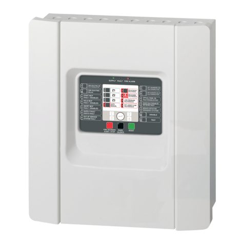
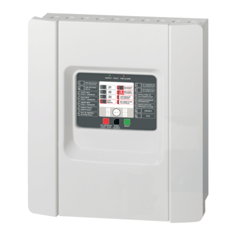
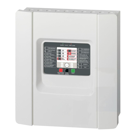
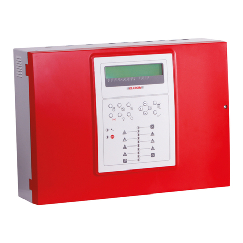
  9. Aritech 1X-E4 Series User manual

Aritech 1X-E4 Series User manual

P/N 501-415403-4-20b • ISS 27JAN23 1
1X-E4 Series Quick Installation Guide
Figure 1: Zone and device connections
Overview
This document includes quick installation information for
your product. For detailed installation information, see
the installation manual.
Zones and zone devices
Connect zone wires and devices as shown in Figure 1.
Zone type and line resistance
Zones
Zone type Line resistance
Odd
Automatic 55 Ω max.
Even
Manual 55 Ω max.
Detectors per zone
Dx700 series detectors
20 max.
Other
detectors 32 max. [1]
[1] Or as defined by local codes and standards
Each manual zone circuit can support up to 32 manual
call points with a resistance of 100 Ω to 680 Ω.
Resistance must be rated at 1 W minimum.
Inputs and outputs
Each control panel has two inputs, marked INPUT1 and
INPUT2.
Input functions
INPUT1
Fire routing inhibit delay
INPUT2
Delays off
Input circuits should have a maximum resistance of
100 Ω(including any cable resistance).
Use outputs OUT1 to OUT4 to connect sounders.
Sounder outputs
Operating mode
Linked to fire detection zone
NEN 2575 with
four evacuation
areas
OUT1 is activated by a fire alarm in zone 1
OUT2 is activated by a fire alarm in zone 2
OUT3 is activated by a fire alarm in zone 3
OUT4 is activated by a fire alarm in zone 4
NEN 2575 with two
evacuation areas
OUT1 and OUT2 are activated by a fire alarm in
zone 1 or zone 2
OUT3 and OUT4 are activated by a fire alarm in
zone 3 or zone 4
2 1X-E4 Series Quick Installation Guide
Operating mode
Linked to fire detection zone
NEN 2575 with
one evacuation
area
All sounder outputs are activated simultaneously
by a fire alarm in any zone
Use outputs OUT5 to OUT6 to connect fire routing
equipment.
Fire routing outputs
OUT5
Fire routing (automatic)
OUT6
Fire routing (manual)
Mains fuses and batteries
Mains fuses
110 VAC [1]
T 3.15 A 250 V
240 VAC
T 2 A 250 V
[1] See your installation manual for 110 VAC operation requirements.
Batteries
The control panel requires two 12 V, 7.2 Ah or 12 V,
12 Ah sealed lead-acid batteries.
Basic configuration
Default configuration
Operating mode
41 (NEN 2575 with four evacuation areas)
Zone end
-of-line Passive
Zone type
Odd zones: Automatic
Even zones: Manual
The configuration controls are located on the control
panel interface.
Configuration controls
Button
Function
1
Scroll to the next configuration menu on the seven-
segment display.
2
Scroll to the next configuration value for the active menu
on the seven-segment display.
3
Scroll to the previous configuration menu on the seven-
segment display.
4
Scroll to the previous configuration value for the active
menu on the seven-segment display.
Enter
Confirm a menu selection or a value selection entry.
The configuration controls are also used to enter the
access level password. The seven-segment display is
visible when the control panel cover is removed.
Seven-segment display
LED
Indications
Mode
Steady: Select a menu using buttons 1 and 3.
— or —
Flashing: Select a submenu using buttons 1 and 3.
Value
Steady: Select a value using buttons 2 and 4.
Basic configuration menu
Selected options from the basic configuration menu are
shown below. The default password for basic
configuration is 3333.
Display
Menu Values
Basic default
configuration
40 to 46
Fire routing delay 00 to 10 minutes
Extended fire routing
delay
00 to 10 minutes
Restore previous
configuration
N/A
Restore factory
configuration
N/A
Exit without saving N/A
Exit and save N/A
1X-E4 Series Quick Installation Guide 3
Basic default configuration presets
A selected list of operating mode configuration presets is
shown below. For a detailed list of all available
configuration presets and characteristics, see your
installation manual.
Display Operating mode
41 NEN 2575 with four evacuation areas
43 NEN 2575 with two evacuation areas
45 NEN 2575 with one evacuation area
See your installation manual for information on how to
configure and enable EN 54-13 zone supervision mode.
Default configured delays for all operating modes are
shown below.
Fire routing delay
1 minute
Extended fire routing delay
3 minutes
Contact information
For contact information, see firesecurityproducts.com.
Copyright © 2023 Carrier. All rights reserved.
4 1X-E4 Series Quick Installation Guide

Other manuals for 1X-E4 Series

2

Other Aritech Control Panel manuals

Aritech 1X-F Series User manual

Aritech

Aritech 1X-F Series User manual

Aritech Moose Z900 User manual

Aritech

Aritech Moose Z900 User manual

Aritech ATS1235 Assembly instructions

Aritech

Aritech ATS1235 Assembly instructions

Aritech ATS1105 User manual

Aritech

Aritech ATS1105 User manual

Aritech 1X-X3E Series User manual

Aritech

Aritech 1X-X3E Series User manual

Aritech ADVISOR CD72 User manual

Aritech

Aritech ADVISOR CD72 User manual

Aritech 1X-X3 User manual

Aritech

Aritech 1X-X3 User manual

Aritech 1X-E4 Series User manual

Aritech

Aritech 1X-E4 Series User manual

Aritech ATS4000 Operating instructions

Aritech

Aritech ATS4000 Operating instructions

Aritech ATS3000 User manual

Aritech

Aritech ATS3000 User manual

Aritech ATS1210 User manual

Aritech

Aritech ATS1210 User manual

Aritech 1X-F Series User manual

Aritech

Aritech 1X-F Series User manual

Aritech 1X-E4 Series User manual

Aritech

Aritech 1X-E4 Series User manual

Aritech 1 3E Series User manual

Aritech

Aritech 1 3E Series User manual

Aritech CS350 User manual

Aritech

Aritech CS350 User manual

Aritech Axon x700 User manual

Aritech

Aritech Axon x700 User manual

Aritech FP2000 Operator's manual

Aritech

Aritech FP2000 Operator's manual

Aritech 1X-X3 User manual

Aritech

Aritech 1X-X3 User manual

Popular Control Panel manuals by other brands

Extron electronics Control Panel CTL208CM Specifications

Extron electronics

Extron electronics Control Panel CTL208CM Specifications

Notifier AFP-2800 Operation, installation & programming manual

Notifier

Notifier AFP-2800 Operation, installation & programming manual

DSC LCD 5500 manual

DSC

DSC LCD 5500 manual

Tiras PRIME 8L Quick start setup guide

Tiras

Tiras PRIME 8L Quick start setup guide

Eldes ESIM4 manual

Eldes

Eldes ESIM4 manual

UPS Aviation Technologies Apollo SL10 installation manual

UPS Aviation Technologies

UPS Aviation Technologies Apollo SL10 installation manual

Siemens FC2005 Installation instruction

Siemens

Siemens FC2005 Installation instruction

COBI ZAD-ECO-V2 manual

COBI

COBI ZAD-ECO-V2 manual

Biamp Apprimo Touch 8i quick start guide

Biamp

Biamp Apprimo Touch 8i quick start guide

Microm FX-3500RCU Installation and operation manual

Microm

Microm FX-3500RCU Installation and operation manual

Chromalox IntelliTrace ITAS-EXT installation manual

Chromalox

Chromalox IntelliTrace ITAS-EXT installation manual

Secutron MR-2320 Series Installation and operation manual

Secutron

Secutron MR-2320 Series Installation and operation manual

C-TEC XFP user manual

C-TEC

C-TEC XFP user manual

BLAUBERG Ventilatoren SE Vento Expert W user manual

BLAUBERG Ventilatoren

BLAUBERG Ventilatoren SE Vento Expert W user manual

D+H RZN 4503-T Original instructions

D+H

D+H RZN 4503-T Original instructions

BFT THALIA P installation manual

BFT

BFT THALIA P installation manual

Beckhoff CP6906-0001-0010 manual

Beckhoff

Beckhoff CP6906-0001-0010 manual

INIM Electronics SmartLoop Programming manual

INIM Electronics

INIM Electronics SmartLoop Programming manual

manuals.online logo
manuals.online logoBrands
  • About & Mission
  • Contact us
  • Privacy Policy
  • Terms and Conditions

Copyright 2025 Manuals.Online. All Rights Reserved.