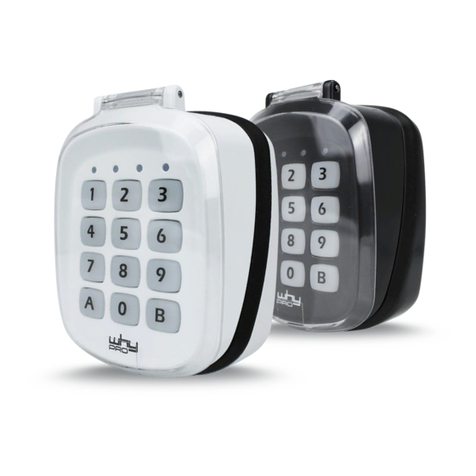
Aritech ACL585 Assembly instructions

© 2021 Carrier 1 / 16 P/N 466-5611-ML • REV A • ISS 30JUL21
ACL585 Standalone Keypad Installation Sheet
EN
DE
ES
FR
IT
NL
1: ACL585
2
3
4
4.
1. 3.
5. 6.
2.
5 mm
(A)
(B)
RS-485
(max. 50 m)
ACL870FL-PB
ACL870SU-PB
Red LED
Relay Status
(Output 2 in )ACL870FL-PB
Orange LED
Key press
and Menu
Green LED
Relay Status (Output 1)
(1) (2) (3)
Push Button
12/24V
NC
COM
NO
T1 Tamper
(6) Orange
(5) Blue
(10)Yellow
(1) Red
(2) Black
(3) Pink
(4) Violet
(7) Brown
(8) Green
(11) White
GND
PB
R 485 AS
R 485 BS
AC DC/
(9) Gray T2 Relay (2A)
Power supply

2 / 16 P/N 466-5611-ML • REV A • ISS 30JUL21
5
6
7
EN: Installation Sheet
Description
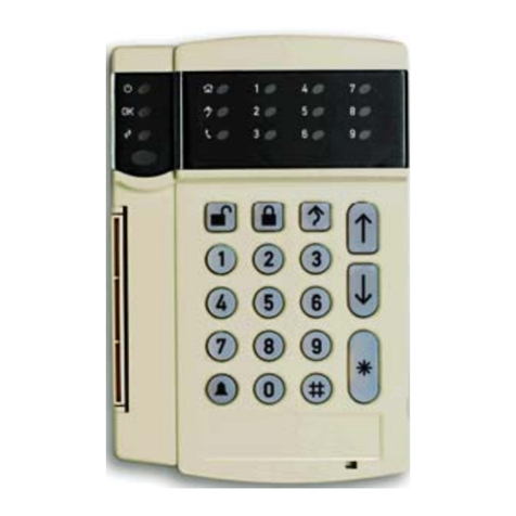
The ACL585 Standalone Keypad is a standalone PIN keypad
in an aluminium housing.
Keypad wiring
See Figure 4.
Figure 4: Keypad wiring
Power supply
12/24V AC/DC
(1) Red
12/24V AC/DC
(2) Black
RS485
RS485 A
(3) Pink
RS485 B
(4) Violet
Push button
GND
(5) Blue
PB
(6) Orange
Tamper
T1
(7) Brown
T2
(8) Green
Relay (2 A)
NC
(9) Gray
COM
(10) Yellow
NO
(11) White
B ( 485)RS
A ( 485)RS
Exit Button
()NO
1N4007
12 VDC +
+12V
+12V
GND
GND
GND
P1
B
N 1O
COM
1 2
Black
Red
Pink
Violet 12 VDC
+
-
1N4001
Diode
N2C
V+
V- +
Orange
Blue
Yellow
Red
Black
Pink
Violet
Brown
Green
White
Gray
ACL870FL-SU
12
ON
12 VDC +
1N4007
Black
Red
Pink
Violet
Black
Brown
Pink
Violet
Red
White
Yellow COM
NO
GND
12V out
A ( 485)RS
B ( 485)RS
max. 50 meters
Orange
Blue
Yellow
Red
Black
Pink
Violet
Brown
Green
White
Gray
ACL870-SU-PB
1. RESET MASTER CODE
2. termination /R 485S ON OFF
(Default - = )ON 120 ohm

P/N 466-5611-ML • REV A • ISS 30JUL21 3 / 16
See Figures 5 and 6 for ACL870FL-PB and ACL870SU-PB
wiring.
To:
From
ACL870FL-
PB
ACL870SU-PB
Door
Magnet /
Door
Strike
ACL585
RS485 –
A (pink)
RS485 –A
RS485 –A
(pink)
ACL585
RS485 –
B (violet)
RS485 –B
RS485 –B
(violet)
ACL585
POWER
GND
GND
GND (black)
ACL585
POWER
+12V
+12V
+12V out
(brown)
Ext. PSU
GND
GND
GND (black)
Ext. PSU
+12V
+12V
+12V (red)
Ext. PSU
GND
NO1 &
COM2
COM (yellow)
Ext. PSU
+12 V
+12V
Door Strike
COM1
NO (white)
Door Magnet
NC2
GND
LEDs
See Figure 3.
There are three LEDs on the keypad:
•Red (item 1): Relay 2 status (on the ACL870FL-PB)
•Green (item 2): Relay 1 status
•Orange (item 3): Key press and menu
DIP switches
See Figure 7.
•1: Reset master code. See “Reset master code” below for
details.
•2: TERM: Set to On for the built-in RS485 120 Ω bus
termination.
Installation
Mounting
Figure 1
(A) Flat surface
(B) Magnet holder
To install the keypad, follow the steps in the figure.
Wiring
See “Keypad wiring” on page 2.
Pairing keypad with ACL870FL-PB or ACL870SU-PB
1. Close the jumper (ACL870FL-PB) or set DIP switch to On
(ACL870SU-PB). The unit beeps continuously, and the red
LED blinks.
2. Open the Jumper / DIP switch
3. Wait for beep and OK beep (short, short, long beep). After
the OK beep, the keypad and ACL870FL-PB / ACL870SU-
PB are paired.
Configuration
Reset master code
Caution: Resetting the master code will delete all user codes.
Resetting the master code will also unpair ACL870FL-PB and
ACL870SU-PB.
See figure 5.
1. Disconnect power and set DIP switch 1 to On (Figure 7,
item 1).
2. Reconnect power.
The keypad beeps continuously.
3. Set DIP switch 1 to off.
Orange LED switches on, long beep sounds.
4. Press 000.
5. Enter the new master code (1 to 8 digits).
6. Press A to confirm.
7. Press B to exit.
Orange LED switches off.
Programming mode
To change keypad options, follow the steps below.
1. Authorize using the master code, or 000 when using the
keypad for the first time.
2. Validate the code by pressing B.
If you are not authorized to enter the programing mode,
the keypad transmits multiple short beeps, and the orange
LED blinks rapidly.
If the code is valid, the programming mode is signalled by
1 short and 1 long beeps, and indicated by the orange
LED on. You can continue with the programming.
3. Enter the option number you want to change. Refer to
“Programming options” below.
4. Press A to validate the change.
If the change is invalid, the keypad transmits multiple short
beeps, and the orange LED blinks rapidly. Return to
step 3.
If the change is valid, it is confirmed by 2 short beeps.
Return to step 3.
To exit the programming mode, press B in any stage of the
programming mode. The orange LED switches off.
Programming options
When in the programming mode, press a number to program
one of the following options.

4 / 16 P/N 466-5611-ML • REV A • ISS 30JUL21
Option
Description
0
Add/change user or master code
To change master code, enter user number 000 followed by
the new master code (1 to 8 digits).
To add or change existing user, enter the user number (001
to 999), and a new user code (1 to 8 digits)
The new user is assigned to Relay 1
1
Set Relay 1 timer
To set toggle relay mode, press 00.
To set time in seconds, press 01 to 99.
The default time is 03 seconds.
2
Set Relay 2 timer
To set toggle relay mode, press 00.
To set time in seconds, press 01 to 99.
The default time is 03 seconds.
3
Assign output to the user
Enter the user number (001 to 999). Next, press 1 for Relay
1, and/or 2 for Relay 2.
4
Not used
5
Slave device
Press 2 to set ACL870FL-PB or ACL870SU-PB as a slave
device.
6
Buzzer, backlight, read range
Press 0 to set buzzer off, or 1 to on. Press 2 to for backlight
off, or 3 to on. Press 4 for backlight on key press, or 5 for
dimmed backlight.
The default values are the following: buzzer on, dimmed
backlight.
7
Not used
8
Delete all users
Press 999 to confirm.
9
Delete single user
Enter user number from 001 to 999.
Next, proceed from the step 4 above –press A to validate the
change.
Example
To assign user code 12345 to the user 5, and relay 2 that
activates for 4 seco nds, assuming default master code 000:
Press 000, B, then 0, 005, 12345, A. Press 3, 005, 2, A.
Press 2, 04, A. Press B to exit the programming mode.
Specifications
Power supply
12 to 24 V AC/DC
Current consumption
max. 70 mA
Outputs
1 relay: 2 A at 24 V AC/DC
User capacity
1000
PIN length
1 to 8 digits
RTE inputs
1
Buzzer, backlight control
Via menu settings
Tamper
Yes
Door open time
0 to 99 s, or toggle (on/off mode)
IP
IP65
Operating Temperature
−20 to +50°C, without condensation
Firmware upgrade
Via RS485 converter
Security
30-second lockout after 8 consecutive
invalid PINs
Regulatory information
Manufacturer
PLACED ON THE MARKET BY:
Carrier Fire & Security Americas Corporation, Inc.
13995 Pasteur Blvd
Palm Beach Gardens, FL 33418, USA
AUTHORIZED EU REPRESENTATIVE:
Carrier Fire & Security B.V.
Kelvinstraat 7, 6003 DH Weert, Netherlands
Product warnings
and disclaimers
THESE PRODUCTS ARE INTENDED FOR SALE
TO AND INSTALLATION BY QUALIFIED
PROFESSIONALS. CARRIER FIRE &
SECURITY CANNOT PROVIDE ANY
ASSURANCE THAT ANY PERSON OR ENTITY
BUYING ITS PRODUCTS, INCLUDING ANY
“AUTHORIZED DEALER” OR “AUTHORIZED
RESELLER”, IS PROPERLY TRAINED OR
EXPERIENCED TO CORRECTLY INSTALL FIRE
AND SECURITY RELATED PRODUCTS.
For more information on warranty disclaimers and
product safety information, please check
https://firesecurityproducts.com/policy/product-
warning/ or scan the QR code.
Certification
Carrier Fire & Security hereby declares that this
device is in compliance with the applicable
requirements and provisions of the Directive
2014/30/EU and/or 2014/35/EU. For more
information see firesecurityproducts.com or
www.aritech.com.
REACH
Product may contain substances that are also
Candidate List substances in a concentration
above 0.1% w/w, per the most recently published
Candidate List found at ECHA Web site.
Safe use information can be found at
https://firesecurityproducts.com/en/content/intrusi
on-intro
2012/19/EU (WEEE directive): Products marked
with this symbol cannot be disposed of as
unsorted municipal waste in the European Union.
For proper recycling, return this product to your
local supplier upon the purchase of equivalent
new equipment, or dispose of it at designated
collection points. For more information see:
recyclethis.info
Product
documentation
Please consult the following web link to retrieve
the electronic version of the product
documentation.
This link will guide you to the EMEA regional
contact page. On this page you can request your
login to the secured web portal where all manuals
are stored.
https://firesecurityproducts.com/en/contact
Contact information
firesecurityproducts.com or www.aritech.com

P/N 466-5611-ML • REV A • ISS 30JUL21 5 / 16
DE: Installationsanleitung
Beschreibung
Die ACL585-Standalone-Tastatur ist eineStandalone-Code-
Tastatur mit Aluminiumgehäuse.
Verdrahtung der Tastatur
Siehe Abbildung 4.
Abbildung 4: Verdrahtung der Tastatur
Stromversorgung
12/24 V AC/DC
(1) Rot
12/24 V AC/DC
(2) Schwarz
RS485
RS485 A
(3) Rosa
RS485 B
(4) Violett
Drucktaster
GND
(5) Blau
PB
(6) Orange
Sabotage
T1
(7) Braun
T2
(8) Grün
Relais (2 A)
NC
(9) Grau
COM
(10) Gelb
NO
(11) Weiß
LEDs
Siehe Abbildung 3.
An der Tastatur befinden sich drei LEDs:
•Rot (Position 1): Status Relais 2 (beim ACL870FL-PB)
•Grün (Position 2): Status Relais 1
•Orange (Position 3): Tastenbetätigung und Menü
DIP-Schalter
Siehe Abbildung 7.
•1: Mastercode zurücksetzen Einzelheiten finden Sie unter
„Zurücksetzen des Mastercodes“ unten.
•2: TERM: Für den integrierten 120-Ω-Busabschluss des
RS485 auf „On“ setzen.
Installation
Montage
Abbildung 1
(A) Glatte Oberfläche
(B) Magnethalterung
Verdrahtung
Siehe „Verdrahtung der Tastatur“oben.
Kopplung der Tastatur mit ACL870FL-PB oder ACL870SU-
PB
1. Setzen Sie Steckbrücke auf (ACL870FL-PB) oder stellen
Sie den DIP-Schalter auf „On“ (ACL870SU-PB). Das
Gerät piept dauerhaft und die rote LED blinkt.
2. Entfernen Sie die Steckbrücke/stellen Sie den DIP-
Schalter um.
3. Warten Sie auf den Signalton und den OK-Signalton (kurz,
kurz, lang). Nach dem OK-Signalton sind die Tastatur und
das ACL870FL-PB/ACL870SU-PB gekoppelt.
Konfiguration
Zurücksetzen des Mastercodes
Vorsicht: Durch Zurücksetzen des Mastercodes werden alle
Benutzercodes gelöscht. Durch das Zurücksetzen des
Mastercodes werden auch das ACL870FL-PB und das
ACL870SU-PB entkoppelt.
Siehe Abbildung 5.
1. Trennen Sie die Stromversorgung und stellen Sie DIP-
Schalter 1 auf „On“ (Abbildung 7, Position 1).
2. Stellen Sie die Stromversorgung wieder her.
Das Bedienteil piept kontinuierlich.
3. Stellen Sie DIP-Schalter 1 auf „Off“.
Die orangefarbene LED leuchtet, ein langer Signalton
ertönt.
4. Geben Sie 000 ein.
5. Geben Sie den neuen Mastercode ein (1 bis 8 Stellen).
6. Drücken Sie A zur Bestätigung.
7. Drücken Sie B zum Beenden.
Die orangefarbene LED erlischt.
Programmiermodus
Befolgen Sie die nachstehenden Schritte, um die Einstellungen
der Tastatur zu ändern:
1. Geben Sie zur Autorisierung den Mastercode oder 000
ein, wenn Sie die Tastatur zum ersten Mal verwenden.
2. Bestätigen Sie den Code, indem Sie B drücken.
Wenn Sie über keine Autorisierung für den
Programmiermodus verfügen, piept die Tastatur mehrmals
kurz und die orangefarbene LED blinkt schnell.
Bei gültigem Code wird durch einen kurzen und einen
langen Piepton sowie durch die orangefarbene LED
angezeigt, dass der Programmiermodus aktiv ist. Sie
können mit der Programmierung beginnen.
3. Geben Sie die Nummer der Option ein, die Sie ändern
möchten. Siehe „Programmieroptionen“unten.
4. Drücken Sie A, um die Änderung zu bestätigen.
Wenn die Änderung ungültig ist, piept das Bedienteil
mehrmals kurz und die orangefarbene LED blinkt schnell.
Kehren Sie zurück zu Schritt 3.
Wenn die Änderung gültig ist, wird sie durch zwei kurze
Signaltöne bestätigt. Kehren Sie zurück zu Schritt 3.
Drücken Sie an einer beliebigen Stelle im
Programmiermodus B, um den Programmiermodus zu
verlassen. Die orangefarbene LED erlischt.
6 / 16 P/N 466-5611-ML • REV A • ISS 30JUL21
Programmieroptionen
Drücken Sie im Programmiermodus eine Zahl, um eine der
folgenden Optionen zu programmieren.
Option
Beschreibung
0
Benutzer- oder Mastercode hinzufügen/ändern
Geben Sie die Benutzernummer 000 gefolgt vom neuen
Mastercode (1 bis 8 Stellen) ein, um den Mastercode zu
ändern.
Geben Sie die Benutzernummer (001 bis 999) und einen
neuen Benutzercode (1 bis 8 Stellen) ein, um einen
vorhandenen Benutzer hinzuzufügen oder zu ändern.
Der neue Benutzer wird Relais 1 zugewiesen.
1
Timer für Relais 1 einstellen
Geben Sie 00 ein, um den Umschaltrelaismodus
einzustellen.
Geben Sie 01 bis 99 ein, um die Zeit in Sekunden
festzulegen.
Die Standardzeit ist 03 Sekunden.
2
Timer für Relais 2 einstellen
Geben Sie 00 ein, um den Umschaltrelaismodus
einzustellen.
Geben Sie 01 bis 99 ein, um die Zeit in Sekunden
festzulegen.
Die Standardzeit ist 03 Sekunden.
3
Ausgang einem Benutzer zuweisen
Geben Sie die Benutzernummer (001 bis 999) ein. Drücken
Sie 1 für Relais 1 und/oder 2 für Relais 2.
4
Nicht verwendet
5
Slave-Gerät
Drücken Sie 2, um das ACL870FL-PB oder das
ACL870SU-PB als Slave-Gerät einzustellen.
6
Summer, Hintergrundbeleuchtung, Lesereichweite
Drücken Sie 0, um den Summer zu aktivieren, oder 1, um
ihn zu deaktivieren. Drücken Sie 2, um die
Hintergrundbeleuchtung zu aktivieren, oder 3, um sie zu
deaktivieren. Drücken Sie 4, um die
Hintergrundbeleuchtung bei Tastenbetätigung zu aktivieren
oder 5, um die gedimmte Hintergrundbeleuchtung zu
aktivieren.
Die Standardeinstellungen sind: Summer aktiviert,
gedimmte Hintergrundbeleuchtung.
7
Nicht verwendet
8
Alle Benutzer löschen
Drücken Sie 999 zur Bestätigung.
9
Einzelnen Benutzer löschen
Geben Sie eine Benutzernummer zwischen 001 und 999
ein.
Fahren Sie mit Schritt 4 oben fort. Drücken Sie A, um die
Änderung zu bestätigen.
Beispiel
So weisen Sie mit dem Standard-Mastercode 000 Benutzer 5
den Benutzercode 12345 und Relais 2 zu, das 4 Sekunden
lang aktiviert wird:
Drücken Sie 000, B, dann 0, 005, 12345, A. Drücken Sie 3,
005, 2, A. Drücken Sie 2, 04, A. Drücken Sie B, um den
Programmiermodus zu verlassen.
Technische Daten
Stromversorgung
12 bis 24 V AC/DC
Stromaufnahme
max. 150mA
Ausgänge
1 Relais: 2 A bei 24 V AC/DC
Benutzerkapazität
1000
PIN-Länge
1 bis 8 Stellen
MTF-Eingänge
2
Spannungsfreie LEDs
2, grün und rot
Summer, Steuerung der
Hintergrundbeleuchtung
Über das Menü
Sabotage
Ja
Türöffnungszeit
0 bis 99 s oder Umschalten (Ein/Aus-
Modus)
IP (IP)
IP65
Betriebstemperatur:
−20 bis +50 °C, nicht kondensierend
Firmware-Upgrade
Über den RS485-Konverter
Sicherheit
30-sekündige Sperre nach 8
aufeinanderfolgenden ungültigen PINs
Rechtliche Hinweise
Hersteller
INVERKEHRBRINGER:
Carrier Fire & Security Americas Corporation Inc.
13995 Pasteur Blvd
Palm Beach Gardens, FL 33418, USA
BEVOLLMÄCHTIGTER EU REPRÄSENDANT:
Carrier Fire & Security B.V.
Kelvinstraat 7, 6003 DH Weert, Niederlande
Produktwarnungen
und Haftungs-
ausschluss
DIESE PRODUKTE SIND FÜR DEN VERKAUF
AN UND DIE INSTALLATION DURCH
QUALIFIZIERTES PERSONAL VORGESEHEN.
CARRIER FIRE & SECURITY ÜBERNIMMT
KEINERLEI GEWÄHRLEISTUNG DAFÜR, DASS
NATÜRLICHE ODER JURISTISCHE
PERSONEN, DIE UNSERE PRODUKTE
ERWERBEN, SOWIE „AUTORISIERTE
HÄNDLER“ ODER „AUTORISIERTE
WIEDERVERKÄUFER“ ÜBER DIE
ERFORDERLICHE QUALIFIKATION UND
ERFAHRUNG VERFÜGEN, UM
BRANDSCHUTZ- ODER
SICHERHEITSTECHNISCHE PRODUKTE
ORDNUNGSGEMÄSS ZU INSTALLIEREN.
Weitere Informationen zu Haftungsausschlüssen
sowie zur Produktsicherheit finden Sie unter
https://firesecurityproducts.com/policy/product-
warning/, oder scannen Sie den QR-Code.
Zertifizierung
Carrier Fire & Security erklärt hiermit, dass dieses
Gerät den geltenden Anforderungen und
Bestimmungen der Richtlinie 2014/30/EU
und/oder 2014/35/EU entspricht. Für weitere
Informationen siehe firesecurityproducts.com
oder www.aritech.com.

P/N 466-5611-ML • REV A • ISS 30JUL21 7 / 16
REACH
Das Produkt kann Stoffe enthalten, die auch unter
Stoffe der Kandidatenliste in einer Konzentration
von mehr als 0,1 % w/w gemäß der zuletzt
veröffentlichten Kandidatenliste auf der ECHA-
Website aufgeführt sind.
Informationen zur sicheren Verwendung finden
Sie unter
https://firesecurityproducts.com/en/content/intrusi
on-intro
2012/19/EU (WEEE): Produkte die mit diesem
Symbol gekennzeichnet sind, dürfen nicht als
unsortierter städtischer Abfall in der europäischen
Union entsorgt werden. Für die korrekte
Wiederverwertung bringen Sie dieses Produkt zu
Ihrem lokalen Lieferanten nach dem Kauf der
gleichwertigen neuen Ausrüstung zurück, oder
entsorgen Sie das Produkt an den
gekennzeichneten Sammelstellen. Weitere
Informationen hierzu finden Sie auf der folgenden
Website: recyclethis.info
Produkt-
Dokumentation
Bitte konsultieren Sie den folgenden Web-Link,
um die elektronische Version der
Produktdokumentation abzurufen.
Dieser Link führt Sie zu der regionalen EMEA-
Kontaktseite. Auf dieser Seite können Sie Ihr
Login zum gesicherten Webportal anfordern, in
dem alle Handbücher gespeichert sind.
https://firesecurityproducts.com/en/contact
Kontaktinformationen
firesecurityproducts.com oder www.aritech.com
ES: Hoja de instalación
Descripción
El teclado autónomo ACL585 es un teclado para PIN en una
carcasa de aluminio.
Cableado del teclado
Consulte la figura 4.
Figura 4: Cableado del teclado
Fuente de
alimentación
12/24 V CA/CC
(1) Rojo
12/24 V CA/CC
(2) Negro
RS485
RS485 A
(3) Rosa
RS485 B
(4) Violeta
Pulsador
GND
(5) Azul
PB
(6) Naranja
Tamper
T1
(7) Marrón
T2
(8) Verde
Relé (2 A)
NC
(9) Gris
COM
(10) Amarillo
NO
(11) Blanco
Indicadores LED
Consulte la figura 3.
En el teclado, hay tres indicadores LED:
•Rojo (elemento 1): estado del relé 2 (en el ACL870FL-PB)
•Verde (elemento 2): estado del relé 1
•Naranja (elemento 3): pulsación de teclas y menú
Conmutadores DIP
Consulte la figura 7.
•1: Restablecer el código maestro. Consulte “Restablecer
código maestro” más adelante para obtener información.
•2: TERM: ajústelo en On (encendido) para la terminación
de bus RS485 integrada de 120 Ω.
Instalación
Montaje
Figura 1
(A) Superficie plana
(B) Soporte del imán
Conexiones
Consulte “Cableado del teclado” más atrás.
Emparejamiento del teclado con ACL870FL-PB o
ACL870SU-PB
1. Cierre el puente (ACL870FL-PB) o coloque el interruptor
DIP en On (encendido) (ACL870SU-PB). La unidad emite
un pitido continuo y el LED rojo parpadea.
2. Abra el interruptor de puente / DIP.
3. Espere el pitido y el pitido OK (pitido corto, corto y largo).
Después del pitido OK, se emparejan el teclado y
ACL870FL-PB / ACL870SU-PB.
Configuración
Restablecer código maestro
Precaución: Al restablecer el código maestro, se eliminarán
todos los códigos de usuario. El restablecimiento del código
maestro también desemparejará ACL870FL-PB y ACL870SU-
PB.
Consulte la figura 5.
1. Desconecte la alimentación y coloque el interruptor DIP 1
en On (encendido) (figura 7, elemento 1).
2. Vuelva a conectar la alimentación.
El teclado emite un pitido continuo.
3. Coloque el interruptor DIP 1 en la posición Off (apagado).
El LED naranja se enciende y suena un pitido largo.
4. Pulse 000.
5. Introduzca el nuevo código maestro (de 1 a 8 dígitos).
6. Pulse A para confirmar.
7. Pulse B para salir.
El LED naranja se apaga.

8 / 16 P/N 466-5611-ML • REV A • ISS 30JUL21
Modo de programación
Para cambiar las opciones del teclado, siga los pasos
indicados a continuación.
1. Proporcione autorización mediante el código maestro o
000 cuando use el teclado por primera vez.
2. Pulse B para validar el código.
Si no está autorizado para acceder al modo de
programación, el teclado transmite varios pitidos cortos y
el LED naranja parpadea rápidamente.
Si el código es válido, el modo de programación se
señaliza con un pitido corto y un pitido largo y se indica
mediante el LED naranja encendido. Puede continuar con
la programación.
3. Introduzca el número de opción que desea cambiar.
Consulte “Opciones de programación” más adelante.
4. Pulse A para validar el cambio.
Si el cambio no es válido, el teclado transmite varios
pitidos cortos y el LED naranja parpadea rápidamente.
Vuelva al paso 3.
Si el cambio es válido, se confirma con dos pitidos cortos.
Vuelva al paso 3.
Para salir del modo de programación, pulse B en cualquier
etapa del modo de programación. El LED naranja se apaga.
Opciones de programación
Cuando esté en el modo de programación, pulse un número
para programar una de las siguientes opciones.
Opción
Descripción
0
Agregar/cambiar usuario o código maestro
Para cambiar el código maestro, introduzca el número de
usuario 000 y, a continuación, el nuevo código maestro (de
1 a 8 dígitos).
Para agregar o cambiar un usuario existente, introduzca el
número de usuario (de 001 a 999) y un nuevo código de
usuario (de 1 a 8 dígitos).
El nuevo usuario se ha asignado al relé 1.
1
Ajustar el temporizador del relé 1
Para ajustar la activación/desactivación del modo de relé,
pulse 00.
Para ajustar el tiempo en segundos, pulse de 01 a 99.
El tiempo predeterminado es de 03 segundos.
2
Ajustar el temporizador del relé 2
Para ajustar la activación/desactivación del modo de relé,
pulse 00.
Para ajustar el tiempo en segundos, pulse de 01 a 99.
El tiempo predeterminado es de 03 segundos.
3
Asignar salida al usuario
Introduzca el número de usuario (de 001 a 999). A
continuación, pulse 1 para el relé 1 o 2 para el relé 2.
4
No utilizado
5
Dispositivo secundario
Pulse 2 para configurar ACL870FL-PB o ACL870SU-PB
como dispositivo secundario.
Opción
Descripción
6
Zumbador, luz de fondo y rango de lectura
Pulse 0 para desactivar el zumbador o 1 para activarlo.
Pulse 2 para apagar la luz de fondo o 3 para encenderla.
Pulse 4 para encender la luz de fondo al presionar una
tecla o 5 para obtener una luz de fondo atenuada.
Los valores predeterminados son los siguientes: zumbador
encendido y luz de fondo atenuada.
7
No utilizado
8
Eliminar todos los usuarios
Pulse 999 para confirmar.
9
Eliminar un usuario
Introduzca el número de usuario del 001 al 999.
A continuación, continúe desde el paso 4 anterior: pulse A
para validar el cambio.
Ejemplo
Para asignar el código de usuario 12345 al usuario 5 y el
relé 2 que se activa durante 4 segundos, presuponiendo el uso
del código maestro predeterminado 000:
Pulse 000, B y, a continuación, 0, 005, 12345 y A. Pulse 3,
005, 2 y A. Pulse 2, 04 y A. Pulse B para salir del modo de
programación.
Especificaciones
Fuente de alimentación
De 12 a 24 V CA/CC
Consumo de corriente
150 mA máx.
Salidas
1 relé: 2 A a 24 V CA/CC
Capacidad de usuarios
1000
Longitud del PIN
De 1 a 8 dígitos
Entradas RTE
2
LED de tensión libre
2, verde y rojo
Zumbador, control de luz
de fondo
A través de la configuración del menú
Tamper
Sí
Tiempo de apertura de
la puerta
De 0 a 99 s o conmutación (modo de
encendido/apagado)
IP
IP65
Temperatura de
funcionamiento
De −20 a +50 °C, sin condensación
Actualización de
firmware
A través del convertidor RS485
Seguridad
Bloqueo de 30 segundos después de
introducir ocho números PIN consecutivos
no válidos.
Información normativa
Fabricante
COLOCADO EN EL MERCADO POR:
Carrier Fire & Security Americas Corporation Inc.
13995 Pasteur Blvd
Palm Beach Gardens, FL 33418, EE. UU.
REPRESENTANTE AUTORIZADO DE LA UE:
Carrier Fire & Security B.V.
Kelvinstraat 7, 6003 DH Weert, Países Bajos

P/N 466-5611-ML • REV A • ISS 30JUL21 9 / 16
Advertencias del
producto y
descargos de
responsabilidad
ESTOS PRODUCTOS ESTÁN DESTINADOS A
LA VENTA A, E INSTALACIÓN POR, UN
PROFESIONAL DE SEGURIDAD
EXPERIMENTADO. CARRIER FIRE &
SECURITY NO PUEDE GARANTIZAR QUE
TODA PERSONA O ENTIDAD QUE COMPRE
SUS PRODUCTOS, INCLUYENDO CUALQUIER
“DISTRIBUIDOR O VENDEDOR AUTORIZADO”,
CUENTE CON LA FORMACIÓN O
EXPERIENCIA PERTINENTE PARA INSTALAR
CORRECTAMENTE PRODUCTOS
RELACIONADOS CON LOS INCENDIOS Y LA
SEGURIDAD.
Para obtener más información sobre exclusiones
de garantía e información de seguridad de
productos, consulte
https://firesecurityproducts.com/policy/product-
warning/ o escanee el código QR.
Certificación
Directivas de la
Unión Europea
Carrier Fire & Security declara por este medio
que este dispositivo cumple los requisitos y
disposiciones aplicables de la Directiva
2014/30/EU y/o 2014/35/EU. Para más
información consulte firesecurityproducts.com o
www.aritech.com.
REACH
Los productos REACH pueden contener
sustancias que están incluidas en la Lista de
sustancias Candidatas en una concentración en
peso superior al 0,1%, según la más reciente
Lista de sustancias Candidatas publicada en la
Web de ECHA.
Puede encontrar información sobre su uso seguro
en
https://firesecurityproducts.com/en/content/intrusi
on-intro
2012/19/EU (directiva WEEE): los productos
marcados con este símbolo no se pueden
desechar como residuos urbanos no clasificados
en la Unión Europea. Para que se pueda realizar
un reciclaje adecuado, devuelva este producto a
su representante de ventas local al comprar un
equipo nuevo similar o deséchelo en los puntos
de recogida designados. Para obtener más
información, consulte: recyclethis.info
Documentación de
producto
Por favor, consulte el siguiente enlace Web para
recuperar la versión electrónica de la
documentación del producto.
Este enlace le guiará a su página de contacto
local de EMEA. En esta página puede solicitar su
acceso al portal web seguro donde se almacenan
todos los manuales.
https://firesecurityproducts.com/en/contact
Información de contacto
firesecurityproducts.com o www.aritech.com
FR : Fiche d’installation
Description
Le clavier ACL585 est un clavier à code autonome doté d’un
boîtier en aluminium.
Câblage du clavier
Voir la Figure 4.
Figure 4 : Câblage du clavier
Alimentation
12/24 V CA/CC
(1) Rouge
12/24 V CA/CC
(2) Noir
RS485
RS485 A
(3) Rose
RS485 B
(4) Violet
Bouton poussoir
GND
(5) Bleu
PB
(6) Orange
Autoprotection
T1
(7) Marron
T2
(8) Vert
Relais (2A)
NF
(9) Gris
COM
(10) Jaune
NO
(11) Blanc
LED
Voir la Figure 3.
Le clavier comporte trois LED :
•Rouge (élément 1) : état du relais 2 (sur l’ACL870FL-PB)
•Verte (élément 2) : état du relais 1
•Orange (élément 3) : activation des touches et menu
Commutateurs DIP
Voir la Figure 7.
•1 : Réinitialisation du code maître. Consultez la section
«Réinitialisation du code maître »en page 10 pour obtenir
des détails.
•2 : TERM. Régler sur On pour la terminaison de bus
RS485 120 Ω intégrée.
Installation
Montage
Figure 1
(A) Surface plane
(B) Support d’aimant
Câblage
Consultez la section «Câblage du clavier »ci-dessus.
Appariement du clavier avec l’ACL870FL-PB ou
l’ACL870SU-PB
1. Fermez le cavalier (ACL870FL-PB) ou activez le
commutateur DIP (ACL870SU-PB). L'appareil émet un
son continu et la LED rouge clignote.

10 / 16 P/N 466-5611-ML • REV A • ISS 30JUL21
2. Ouvrez le cavalier/commutateur DIP.
3. Attendez le signal sonore de confirmation (son court,
court, long). Le clavier et l’ACL870FL-PB/ACL870SU-PB
sont ensuite appairés.
Configuration
Réinitialisation du code maître
Attention : la réinitialisation du code maître supprime tous les
codes d’utilisateur, et dissocie l’ACL870FL-PB et l’ACL870SU-
PB.
Voir la Figure 5.
1. Débranchez l’alimentation et mettez le commutateur DIP 1
sur On (Figure 7, élément 1).
2. Rebranchez l’alimentation.
Le clavier émet un son continu.
3. Réglez le commutateur DIP 1 sur OFF (désactivé).
La LED orange s’allume, et un son long retentit.
4. Appuyez sur 000.
5. Saisissez le nouveau code maître (1 à 8 chiffres).
6. Appuyez sur A pour confirmer.
7. Appuyez sur B pour quitter.
La LED orange s’éteint.
Mode de programmation
Pour modifier vos options de clavier, suivez ces étapes :
1. Autorisez l’utilisation du code maître ou du code 000 lors
de la première utilisation du clavier.
2. Validez le code en appuyant sur B.
Si vous n’êtes pas autorisé à passer en mode de
programmation, le clavier émet plusieurs sons courts, et la
LED orange clignote rapidement.
Si le code est valide, le mode de programmation est
signalé par un son court suivi d’un son long, et la LED
orange s’allume. Vous pouvez poursuivre la
programmation.
3. Saisissez le numéro d’option que vous souhaitez modifier.
Consultez la section «Options de programmation », ci-
dessous.
4. Appuyez sur A pour valider la modification.
Si la modification n’est pas valide, le clavier émet
plusieurs sons courts, et la LED orange clignote
rapidement. Revenez à l’étape 3.
Si la modification est valide, elle est confirmée par 2 sons
courts. Revenez à l’étape 3.
Pour quitter le mode de programmation, appuyez sur B à tout
moment. La LED orange s’éteint.
Options de programmation
En mode de programmation, appuyez sur un numéro pour
programmer l’une des options suivantes.
Option
Description
0
Ajouter/modifier un code maître ou d’utilisateur
Pour modifier le code maître, saisissez le numéro
d’utilisateur 000 suivi du nouveau code maître (1 à 8
chiffres).
Pour ajouter ou modifier un utilisateur existant, saisissez le
numéro d’utilisateur (001 à 999) et un nouveau code
d’utilisateur (1 à 8 chiffres).
Le nouvel utilisateur est affecté au relais 1.
1
Régler la temporisation du relais 1
Pour régler le mode de relais, appuyez sur 00.
Pour définir une durée en secondes, saisissez une valeur
comprise entre 01 et 99.
La valeur par défaut est de 03 secondes.
2
Régler la temporisation du relais 2
Pour régler le mode de relais, appuyez sur 00.
Pour définir une durée en secondes, saisissez une valeur
comprise entre 01 et 99.
La valeur par défaut est de 03 secondes.
3
Attribuer la sortie à l’utilisateur
Saisissez le numéro d’utilisateur (001 à 999). Ensuite,
appuyez sur 1 pour le relais 1 et/ou 2 pour le relais 2.
4
Non utilisé
5
Appareil esclave
Appuyez sur 2 pour définir l’ACL870FL-PB ou l’ACL870SU-
PB comme appareil esclave.
6
Buzzer, rétroéclairage, plage de lecture
Appuyez sur 0 pour désactiver le buzzer ou sur 1 pour
l’activer. Appuyez sur 2 pour désactiver le rétroéclairage ou
sur 3 pour l’activer. Appuyez sur 4 pour activer le
rétroéclairage à l’appui d’une touche ou sur 5 pour atténuer
le rétroéclairage.
Par défaut, le buzzer est activé et le rétroéclairage atténué.
7
Non utilisé
8
Supprimer tous les utilisateurs
Appuyez sur 999 pour confirmer.
9
Supprimer un utilisateur
Saisissez le numéro de l’utilisateur, compris entre 001 et
999.
Passez à l’étape 4 ci-dessus. Appuyez sur A pour valider la
modification.
Exemple
Pour attribuer le code utilisateur 12345 à l’utilisateur 5 et au
relais 2 qui s’active pendant 4 secondes, en supposant que le
code maître par défaut est 000 :
Appuyez sur 000, B, puis 0, 005, 12345, A. Appuyez sur 3,
005, 2, A. Appuyez sur 2, 04, A. Appuyez sur B pour quitter le
mode de programmation.
Caractéristiques
Alimentation
12 à 24 V CA/CC
Consommation
150 mA max.
Sorties
1 relais : 2 A à 24 V CA/CC
Capacité utilisateurs
1 000
Longueur du code
1 à 8 chiffres

P/N 466-5611-ML • REV A • ISS 30JUL21 11 / 16
Entrées DDS
2
LED à tension libre
2, verte et rouge
Buzzer, contrôle du
rétroéclairage
Via les paramètres du menu
Autoprotection
Oui
Durée d’ouverture de la porte
0 à 99 s, ou basculement
(marche/arrêt)
IP
IP65
Température de fonctionnement
−20 à 50 °C, sans condensation
Mise à niveau du firmware
Via convertisseur RS-485
Sécurité
Verrouillage de 30 secondes après
8 codes invalides consécutifs
Information réglementaire
Fabriquant
MISE SUR LE MARCHÉ PAR :
Carrier Fire & Security Americas Corporation Inc.
13995 Pasteur Blvd
Palm Beach Gardens, FL 33418, USA
REPRÉSENTANT DE L’UNION EUROPÉENNE
AUTORISÉ:
Carrier Fire & Security B.V.
Kelvinstraat 7, 6003 DH Weert, Pays-Bas
Avertissements et
avis de non-
responsabilité
CES PRODUITS SONT DESTINÉS À DES
PROFESSIONNELS EXPÉRIMENTÉS, QUI
DOIVENT ÉGALEMENT SE CHARGER DE
LEUR INSTALLATION. CARRIER FIRE &
SECURITY NE PEUT GARANTIR QU’UNE
PERSONNE OU ENTITÉ FAISANT
L’ACQUISITION DE CEUX-CI, Y COMPRIS UN
REVENDEUR AGRÉÉ, DISPOSE DE LA
FORMATION OU DE L’EXPÉRIENCE REQUISE
POUR PROCÉDER À CETTE MÊME
INSTALLATION DE FAÇON APPROPRIÉE.
Pour obtenir des informations supplémentaires
sur les garanties et la sécurité, rendez-vous à
l’adresse
https://firesecurityproducts.com/policy/product-
warning/ ou scannez le code QR.
Certification
Directives
européennes
Carrier Fire & Security déclare par la présente
que cet appareil est conforme aux exigences et
dispositions applicables de la directive
2014/30/EU et / ou 2014/35/EU. Pour plus
d'informations, voir firesecurityproducts.com ou
www.aritech.com.
REACH
Ce produit peut contenir des substances figurant
également sur la Liste de substances candidates
à une concentration supérieure à 0,1 % p/p, selon
la Liste de substances candidates la plus récente
publiée sur le site web de l’Agence européenne
des produits chimiques (ECHA).
Vous trouverez des renseignements sur
l'utilisation sécuritaire du produit à l'adresse
https://firesecurityproducts.com/en/content/intrusi
on-intro
2012/19/EU (WEEE) : Les produits marqués de
ce symbole peuvent pas être éliminés comme
déchets municipaux non triés dans l’Union
européenne. Pour le recyclage, retourner ce
produit à votre fournisseur au moment de l’achat
d’un nouvel équipement équivalent, ou à des
points de collecte désignés. Pour plus
d’informations, voir : recyclethis.info
Documentation
produit
Veuillez consulter le lien Web suivant pour
récupérer la version électronique de la
documentation du produit.
Ce lien vous guidera vers la page de contact
régional EMEA. Sur cette page, vous pouvez
demander votre connexion au portail Web
sécurisé où tous les manuels sont stockés.
https://firesecurityproducts.com/en/contact
Pour nous contacter
firesecurityproducts.com ou www.aritech.com
IT: Istruzioni per l'installazione
Descrizione
La tastiera autonoma ACL585 è una tastiera per PIN
autonoma in un alloggiamento in alluminio.
Cablaggio della tastiera
Vedere la Figura 4.
Figura 4: Cablaggio della tastiera
Alimentazione
12/24 V CA/CC
(1) Rosso
12/24 V CA/CC
(2) Nero
RS485
RS485 A
(3) Rosa
RS485 B
(4) Viola
Pulsante
GND
(5) Blu
PB
(6) Arancione
Manomissione
T1
(7) Marrone
T2
(8) Verde
Relè (2 A)
NC
(9) Grigio
COM
(10) Giallo
NA
(11) Bianco
LED
Vedere la Figura 3.
Sulla tastiera sono presenti tre LED:
•Rosso (1): stato relè 2 (su ACL870FL-PB)
•Verde (2): stato relè 1
•Arancione (3): pressione tasti e menu
DIP switch
Vedere la Figura 7.
•1: reset codice principale. Per i dettagli, consultare la
sezione “Reset del codice principale” a pagina 12.
•2: TERM: impostare su On per la terminazione bus RS485
da 120 Ω integrata.

12 / 16 P/N 466-5611-ML • REV A • ISS 30JUL21
Installazione
Montaggio
Figura 1
(A) Superficie piana
(B) Supporto magnete
Cablaggio
Consultare la sezione “Cablaggio della tastiera” a pagina 11.
Associazione della tastiera con ACL870FL-PB o
ACL870SU-PB
1. Chiudere il ponticello (ACL870FL-PB) o impostare il DIP
switch su On (ACL870SU-PB). L'unità emette un segnale
acustico continuo e il LED rosso lampeggia.
2. Aprire il ponticello/DIP switch
3. Attendere il segnale acustico e il segnale acustico di OK
(breve, breve, lungo). Dopo il segnale acustico di OK, la
tastiera e ACL870FL-PB/ACL870SU-PB sono associati.
Configurazione
Reset del codice principale
Attenzione: il reset del codice principale elimina tutti i codici
utente. Il reset del codice principale annulla inoltre
l'associazione con ACL870FL-PB e ACL870SU-PB.
Vedere la Figura 5.
1. Scollegare l'alimentazione e impostare il DIP switch 1 su
On (Figura 7, punto 1).
2. Ricollegare l'alimentazione.
La tastiera emette un segnale acustico continuo.
3. Impostare il DIP switch 1 sulla posizione OFF.
Il LED arancione si accende, viene emesso un segnale
acustico lungo.
4. Premere 000.
5. Immettere il nuovo codice principale (da 1 a 8 cifre).
6. Premere A per confermare.
7. Premere B per uscire.
Il LED arancione si spegne
Modalità di programmazione
Per modificare le impostazioni della tastiera, attenersi alla
procedura di seguito.
1. Effettuare l'autorizzazione utilizzando il codice principale,
o 000 quando si utilizza la tastiera per la prima volta.
2. Convalidare il codice premendo B.
Se non si è autorizzati a entrare in modalità di
programmazione, la tastiera emette diversi segnali acustici
brevi e il LED arancione lampeggia rapidamente.
Se il codice è valido, la modalità di programmazione viene
segnalata da 1 segnale acustico breve e 1 lungo, e
indicata dal LED arancione acceso. È possibile proseguire
con la programmazione.
3. Immettere il numero di opzione che si desidera modificare.
Consultare “Opzioni di programmazione” più sotto.
4. Premere A per convalidare la modifica.
Se la modifica non è valida, la tastiera emette diversi
segnali acustici brevi e il LED arancione lampeggia
rapidamente. Tornare al punto 3.
Se la modifica è valida, viene confermata da 2 segnali
acustici brevi. Tornare al punto 3.
Per uscire dalla modalità di programmazione, premere B in
qualsiasi fase della modalità di programmazione. Il LED
arancione si spegne.
Opzioni di programmazione
In modalità di programmazione, premere un numero per
programmare una delle opzioni di seguito.
Opzione
Descrizione
0
Aggiunta/modifica di codice utente o codice principale
Per modificare il codice principale, inserire il numero utente
000 seguito dal nuovo codice principale (da 1 a 8 cifre).
Per aggiungere o modificare un utente esistente, inserire il
numero utente (da 001 a 999) e un nuovo codice utente (da
1 a 8 cifre)
Il nuovo utente viene assegnato al relè 1
1
Impostazione del timer del relè 1
Per impostare la modalità relè di commutazione, premere
00.
Per impostare il tempo in secondi, premere da 01 a 99.
L’intervallo di tempo predefinito è 03 secondi.
2
Impostazione del timer del relè 2
Per impostare la modalità relè di commutazione, premere
00.
Per impostare il tempo in secondi, premere da 01 a 99.
L’intervallo di tempo predefinito è 03 secondi.
3
Assegnazione di uscita all'utente
Immettere il numero utente (da 001 a 999). Premere quindi
1 per il relè 1 e/o 2 per il relè 2.
4
Non utilizzato
5
Dispositivo secondario
Premere 2 per impostare ACL870FL-PB o ACL870SU-PB
come dispositivo secondario.
6
Cicalino, retroilluminazione, portata di lettura
Premere 0 per disattivare il cicalino o 1 per attivarlo.
Premere 2 per disattivare la retroilluminazione o 3 per
attivarla. Premere 4 per la retroilluminazione alla pressione
dei tasti o 5 per la retroilluminazione attenuata.
I valori predefiniti sono i seguenti: cicalino attivato,
retroilluminazione attenuata.
7
Non utilizzato
8
Eliminazione di tutti gli utenti
Premere 999 per confermare.
9
Eliminazione di un singolo utente
Immettere il numero utente da 001 a 999.
Quindi, procedi dal punto 4 precedente; premere A per
convalidare la modifica.

P/N 466-5611-ML • REV A • ISS 30JUL21 13 / 16
Esempio
Per assegnare il codice utente 12345 all'utente 5, e relè 2 che
si attiva per 4 secondi, presupponendo il codice principale
predefinito 000:
Premere 000, B, quindi 0, 005, 12345, A. Premere 3, 005, 2, A.
Premere 2, 04, A. Premere B per uscire dalla modalità di
programmazione.
Specifiche
Alimentazione
Da 12 a 24 V CA/CC
Assorbimento di corrente
Max. 150 mA
Uscite
1 relè: 2 A a 24 V CA/CC
Capacità utenti
1.000
Lunghezza PIN
Da 1 a 8 cifre
Ingressi RTE
2
LED senza tensione
2, verde e rosso
Cicalino, controllo della
retroilluminazione
Tramite impostazioni di menu
Manomissione
Sì
Tempo apertura varco
Da 0 a 99 s, o commutazione
(modalità on/off)
IP
IP65
Temperatura di funzionamento
Da -20 a +50 °C, senza condensa
Aggiornamento firmware
Tramite convertitore RS485
Sicurezza
Blocco di 30 secondi dopo 8 PIN
non validi consecutivi
Certificazione e conformità
Costruttore
MESSO SUL MERCATO DA:
Carrier Fire & Security Americas Corporation Inc.
13995 Pasteur Blvd
Palm Beach Gardens, FL 33418, USA
AUTORIZZATO RAPPRESENTANTE UE:
Carrier Fire & Security B.V.
Kelvinstraat 7, 6003 DH Weert, Netherlands
Avvertenze sul
prodotto e
dichiarazioni di
non responsabilità
QUESTI PRODOTTI SONO DESTINATI ALLA
VENDITA A, E DEVONO ESSERE MONTATI
DA, UN ESPERTO QUALIFICATO. CARRIER
FIRE & SECURITY NON PUÒ GARANTIRE CHE
LE PERSONE O GLI ENTI CHE ACQUISTANO I
SUOI PRODOTTI, COMPRESI I “RIVENDITORI
AUTORIZZATI”, DISPONGANO DELLA
FORMAZIONE O ESPERIENZA ADEGUATE
PER ESEGUIRE LA CORRETTA
INSTALLAZIONE DI PRODOTTI PER LA
SICUREZZA E PER LA PROTEZIONE
ANTINCENDIO.
Per ulteriori informazioni sulle esclusioni di
garanzia e sulla sicurezza dei prodotti, consultare
il sito
https://firesecurityproducts.com/policy/product-
warning/ oppure eseguire la scansione del codice
QR.
Certificazione
Direttive Unione
Europea
Carrier Fire & Security dichiara che questo
dispositivo è conforme ai requisiti applicabili e alle
disposizioni della Direttiva 2014/30/UE e/o
2014/35/UE. Per ulteriori informazioni, vedere
firesecurityproducts.com o www.aritech.com.
REACH
Il prodotto può contenere sostanze che sono
anche sostanze appartenenti all’elenco di
candidati per una concentrazione superiore allo
0,1% p / p, l'elenco dei candidati pubblicato più di
recente è disponibile sul sito Web dell'ECHA.
Informazioni sull'uso sicuro sono disponibili
all'indirizzo
https://firesecurityproducts.com/en/content/intrusi
on-intro
2012/19/EU (Direttiva WEEE): I prodotti
contrassegnati con questo simbolo, non possono
essere smaltiti nei comuni contenitori per lo
smaltimento rifiuti, nell’ Unione Europea. Per il
loro corretto smaltimento, potete restituirli al
vostro fornitore locale a seguito dell’acquisto di un
prodotto nuovo equivalente, oppure rivolgervi e
consegnarli presso i centri di raccolta preposti.
Per maggiori informazioni vedere: recyclethis.info
Documentazione
Prodotto
Consultare il seguente collegamento Web per
recuperare la versione elettronica della
documentazione del prodotto.
Questo link ti guiderà alla pagina dei contatti
regionali EMEA. In questa pagina è possibile
richiedere l'accesso al portale Web protetto in cui
sono memorizzati tutti i manuali.
https://firesecurityproducts.com/en/contact
Informazioni di contatto
firesecurityproducts.com o www.aritech.com
NL: Installatieblad
Omschrijving
Het ACL585 standalone codeslot is een standalone PIN-
codeslot in een aluminium behuizing.
Bedrading codeslot
Zie afbeelding 4.
Afbeelding 4: Bedrading codeslot
Netvoeding
12/24 V AC/DC
(1) Rood
12/24 V AC/DC
(2) Zwart
RS485
RS485 A
(3) Roze
RS485 B
(4) Paars
Drukknop
GND
(5) Blauw
PB
(6) Oranje
Manipulatie
T1
(7) Bruin
T2
(8) Groen
Relais (2A)
NC
(9) Grijs
COM
(10) Geel
NO
(11) Wit
Leds
Zie afbeelding 3.

14 / 16 P/N 466-5611-ML • REV A • ISS 30JUL21
Het codeslot heeft drie ledlampjes:
•Rood (item 1): Status relais 2 (op de ACL870FL-PB)
•Groen (item 2): Relais 1 aan
•Oranje (item 3): Toets indrukken en menu
DIP-schakelaars
Zie afbeelding 7.
•1: Mastercode resetten. Zie “Mastercode resetten”
hieronder voor details.
•2: TERM: Stel in op On voor de ingebouwde RS485 120 Ω
busaansluiting.
Installatie
Montage
Afbeelding 1
(A) Vlak oppervlak
(B) Magneethouder
Bedrading
Zie “Bedrading codeslot” op pagina 13.
Codeslot koppelen met ACL870FL-PB of ACL870SU-PB
1. Sluit de jumper (ACL870FL-PB) of zet de DIP-schakelaar
op On (ACL870SU-PB). Het apparaat piept continu en het
rode ledlampje knippert.
2. Open de Jumper/DIP-schakelaar
3. Wacht op een pieptoon of OK-pieptoon (korte, korte, lange
piep). Na de OK-pieptoon zijn het en de ACL870FL-
PB/ACL870SU-PB gekoppeld.
Configuratie
Mastercode resetten
Let op: Door de mastercode te resetten, worden alle
gebruikerscodes verwijderd. Het resetten van de mastercode
zal ook de ACL870FL-PB en ACL870SU-PB ontkoppelen.
Zie afbeelding 5.
1. Schakel de voeding uit en zet DIP-schakelaar 1 op On
(afbeelding 7, item 1).
2. Sluit de voeding weer aan.
Het codeslot piept continu.
3. Schakel DIP-schakelaar 1 uit.
Het oranje ledlampje gaat branden, er klinkt een lange
pieptoon.
4. Druk op 000.
5. Voer de nieuwe mastercode in (1 tot 8 cijfers).
6. Druk op A om te bevestigen.
7. Druk op B om af te sluiten.
Het oranje ledlampje gaat uit.
Programmeermodus
Volg de onderstaande stappen om de opties van het codeslot
te wijzigen.
1. Autoriseer met behulp van de mastercode of 000 wanneer
u het codeslot voor de eerste keer gebruikt.
2. Valideer de code door op B te drukken.
Als u niet bevoegd bent om de programmeermodus te
openen, zendt het codeslot meerdere korte pieptonen uit
en het oranje ledlampje knippert snel.
Als de code geldig is, wordt de programmeermodus
gesignaleerd door 1 korte en 1 lange pieptoon en blijft het
oranje ledlampje branden. U kunt doorgaan met
programmeren.
3. Voer het optienummer in dat u wilt wijzigen. Raadpleeg
“Programmeeropties” hieronder.
4. Druk op A om de wijziging te valideren.
Als de wijziging ongeldig is, zendt het codeslot meerdere
korte pieptonen uit en het oranje ledlampje knippert snel.
Ga terug naar stap 3.
Als de wijziging geldig is, wordt deze bevestigd door 2
korte pieptonen. Ga terug naar stap 3.
Om de programmeermodus af te sluiten, drukt u op B in een
willekeurige fase van de programmeermodus. Het oranje
ledlampje schakelt uit.
Programmeeropties
Druk in de programmeermodus op een nummer om een van
de volgende opties te programmeren.
Optie
Omschrijving
0
Gebruikers- of mastercode toevoegen/wijzigen
Om de mastercode te wijzigen, voert u gebruikersnummer
000 in, gevolgd door de nieuwe mastercode (1 tot 8 cijfers).
Om een bestaande gebruiker toe te voegen of te wijzigen,
voert u het gebruikersnummer (001 tot 999) en een nieuwe
gebruikerscode (1 tot 8 cijfers) in
De nieuwe gebruiker wordt toegewezen aan relais 1
1
Stel relais 1-timer in
Druk op 00 om de toggle-relaismodus in te stellen.
Druk op 01 tot 99 om de tijd in seconden in te stellen.
De standaardinstelling is 03 seconden.
2
Stel relais 2-timer in
Druk op 00 om de toggle-relaismodus in te stellen.
Druk op 01 tot 99 om de tijd in seconden in te stellen.
De standaardinstelling is 03 seconden.
3
Uitgang toewijzen aan de gebruiker
Voer het gebruikersnummer in (001 tot 999). Druk
vervolgens op 1 voor relais 1 en/of 2 voor relais 2.
4
Niet gebruikt
5
Slave-apparaat
Druk op 2 om ACL870FL-PB of ACL870SU-PB als slave-
apparaat in te stellen.

P/N 466-5611-ML • REV A • ISS 30JUL21 15 / 16
Optie
Omschrijving
6
Zoemer, achtergrondverlichting, leesbereik
Druk op 0 om de zoemer uit te zetten, of op 1 om deze aan
te zetten. Druk op 2 om de achtergrondverlichting uit te
zetten, of op 3 om deze aan te zetten. Druk op 4 voor
achtergrondverlichting bij het indrukken van een toets of op
5 voor gedimde achtergrondverlichting.
De standaardwaarden zijn als volgt: zoemer aan, gedimde
achtergrondverlichting.
7
Niet gebruikt
8
Alle gebruikers wissen
Druk op 999 om te bevestigen.
9
Eén gebruiker wissen
Voer een gebruikersnummer van 001 tot en met 999 in.
Ga vervolgens verder vanaf stap 4 hierboven –druk op A om
de wijziging te valideren.
Voorbeeld
Doe het volgende om gebruikerscode 12345 toe te wijzen aan
gebruiker 5 en relais 2 dat gedurende 4 seconden wordt
geactiveerd, uitgaande van de standaard mastercode 000:
druk op 000, B, vervolgens op 0, 005, 12345, A. Druk op 3,
005, 2, A. Druk op 2, 04, A. Druk op B om de
programmeermodus af te sluiten.
Specificaties
Netvoeding
12 tot 24 V AC/DC
Stroomverbruik
max. 150mA
Uitgangen
1 relais: 2 A bij 24 V AC/DC
Gebruikerscapaciteit
1000
Lengte pincode
1 tot 8 cijfers
RTE-ingangen
2
Vrije spanningsledlampjes
2, groen en rood
Zoemer,
achtergrondverlichtingregeling
Via menu-instellingen
Manipulatie
Ja
Tijd geopende deur
0 tot 99 s, of wisselen (aan/uit-
modus)
IP
IP65
Bedrijfstemperatuur
−20 tot +50 °C, zonder condensatie
Firmware bijwerken
Via RS485-omvormer
Beveiliging
30 seconden vergrendeling na 8
opeenvolgende ongeldige pincodes
Algemene Informatie
Fabrikant
OP DE MARKT GEBRACHT DOOR:
Carrier Fire & Security Americas Corporation Inc.
13995 Pasteur Blvd
Palm Beach Gardens, FL 33418, USA
GEAUTORISEERDE EU
VERTEGENWOORDIGER:
Carrier Fire & Security B.V.
Kelvinstraat 7, 6003 DH Weert, Nederland
Waarschuwingen
en disclaimers met
betrekking tot de
producten
DEZE PRODUCTEN ZIJN BEDOELD VOOR
VERKOOP AAN EN INSTALLATIE DOOR
GEKWALIFICEERDE BEROEPSKRACHTEN.
CARRIER FIRE & SECURITY GEVEN GEEN
GARANTIE DAT EEN PERSOON OF ENTITEIT
DIE DIENS PRODUCTEN AANSCHAFT,
WAARONDER “GEAUTORISEERDE DEALERS”
OF “GEAUTORISEERDE
WEDERVERKOPERS”, OP DE JUISTE WIJZE
ZIJN OPGELEID OF VOLDOENDE ERVARING
HEBBEN OM PRODUCTEN MET BETREKKING
TOT BRAND EN BEVEILIGING OP DE JUISTE
WIJZE TE INSTALLEREN.
Zie voor meer informatie over garantiebepalingen
en productveiligheid
https://firesecurityproducts.com/policy/product-
warning/ of scan de QR-code.
Certificatie
Richtlijnen
Europese Unie
Carrier Fire & Security verklaart hierbij dat dit
apparaat voldoet aan de toepasselijke eisen en
bepalingen van de Regelgeving 2014/30/EU en/of
2014/35/EU. Voor meer informatie zie
firesecurityproducts.com of www.aritech.com.
REACH
Product kan stoffen bevatten die ook stoffen van
de kandidatenlijst zijn in een concentratie van
meer dan 0,1% w/w, volgens de meest recent
gepubliceerde kandidatenlijst op ECHA-website.
Informatie over veilig gebruik is te vinden op
https://firesecurityproducts.com/en/content/intrusi
on-intro
2012/19/EU (WEEE richtlijn): Producten met deze
label mogen niet verwijdert worden via de
gemeentelijke huisvuilscheiding in de Europese
Gemeenschap. Voor correcte vorm van kringloop,
geef je de producten terug aan jou locale
leverancier tijdens het aankopen van een
gelijkaardige nieuw toestel, of geef het af aan een
gespecialiseerde verzamelpunt. Meer informatie
vindt u op de volgende website: recyclethis.info
Product
documentatie
Raadpleeg de volgende weblink om de digitale
versie van de productdocumentatie te
downloaden.
Deze link leidt u naar de regionale contactpagina
van EMEA. Op deze pagina kunt u uw login
aanvragen bij de beveiligde webportal waar alle
handleidingen zijn opgeslagen.
https://firesecurityproducts.com/en/contact
Contact informatie
firesecurityproducts.com of www.aritech.com

16 / 16 P/N 466-5611-ML • REV A • ISS 30JUL21
Table of contents
Languages:
Other Aritech Keypad manuals

Aritech
Aritech CS-175 Series User manual

Aritech
Aritech ATS1136 Assembly instructions

Aritech
Aritech ACL599 Owner's manual

Aritech
Aritech ATS1155 User manual

Aritech
Aritech ATS1135 Assembly instructions

Aritech
Aritech CS-175-275-575 Series User manual

Aritech
Aritech ATS111-N Series Assembly instructions

Aritech
Aritech ATS4000 User manual

Aritech
Aritech ACL805SUW-RDPX Assembly instructions

Aritech
Aritech ACL875FL-KP Assembly instructions