Arjo SARA PLUS Installation guide

SARA PLUS
THE ADVANCED STANDING
AND RAISING AID
KKX52180M-EN
Issue 2
October 2006
OPERATING AND PRODUCT
CARE INSTRUCTIONS

2
© ARJO
ARJO products are patented or patent pending.
Patent information is available by contacting ARJO.
The policy of Arjo is one of continuous
development and we therefore reserve the right to
make technical alterations without notice. The
content of this publication may not be copied either
whole or in part without the consent of ARJO.
This product has been manufactured for ARJO by :
Medibo Medical Products N.V.
Heikant 5
B-3930 Hamont-Achel
Belgium
‘Sara Plus’ and ‘ARJO’ are registered trademarks
of GETINGE AB.
The SARA PLUS is produced in Belgium by
MEDIBO MEDICAL PRODUCTS for GETINGE
AB and sold under the ARJO brand.

SECTION Page
No.
Foreword..................................................... 4
Safety Instructions ..................................... 5
Intended Use............................................. 5
Product description/function .................... 6-10
Parts referred to in this manual................. 6
Control Handset........................................ 7
Dual Control panel ................................... 7
Emergency stop button (red) .................... 7
Reset button (green) ................................. 8
Automatic cutout ...................................... 8
Automatic stop function ........................... 8
System failure lower override .................. 8
Battery discharge indicator....................... 8
Hour meter................................................ 8
Chassis castor Brakes ............................... 8
Straight line steering function (option)..... 8
Arc-Rest.................................................... 9
Foot support.............................................. 9
Proactive pad ............................................ 9
Lower leg straps ....................................... 9
Adjustable width chassis legs................... 10
Commode Seat (accessory) ...................... 10
Using your Sara Plus.................................. 11-23
Using your Sara Plus for toileting and
transport.................................................... 11
Standing sling ........................................... 12
Transfer and walking sling ....................... 14
Using the sling for transfer ................... 14
Using the sling for walking practice ..... 17
Scale (if fitted).......................................... 20-23
Lifter Battery charging ............................. 24-25
Warnings for charging .............................. 24
General safety Practices for Batteries ...... 24
Care of your Sara Plus............................... 26-28
General lifter care..................................... 26
Environmental advice............................... 27
Periodic Testing........................................ 27
Cleaning and disinfecting the toilet
commode chair and frame (if fitted)......... 27
Servicing advice ....................................... 28
Labels .......................................................... 29
Technical Specification .............................. 30-31
Lifter Dimensions..................................... 31
3
Contents

4
Thank you for purchasing ARJO equipment
Your Sara Plus is part of a series of quality products
designed especially for hospitals, nursing homes
and other health care uses.
We are dedicated to serving your needs and
providing the best products available along with
training that will bring your staff maximum benefit
from every ARJO product.
Please contact us if you have any questions about
the operation or maintenance of your ARJO
equipment.
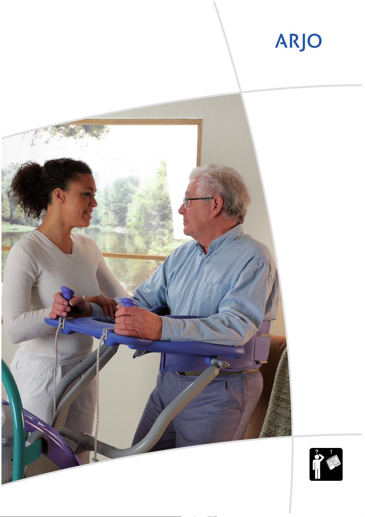
The touch panel label on the dual control panel
displays several instruction symbols. The letter (i)
shown on the open book icon indicates
‘information’, and is an instruction to always read
the operating instructions before use. (See fig 1).
The expected operational life of your ARJO lifter is
10 (ten) years from the date of manufacture,
providing the following conditions are adhered to:-
Conditions
• The unit is cared for and serviced in accordance
with recommended, published “Operating and
Product Care Instructions” and the “Preventive
Maintenance Schedule”.
• The unit is maintained to the minimum
requirements as published in the “Preventive
Maintenance Schedule”.
• The servicing and product care, in accordance
with ARJO requirements, must begin on first
use of the unit by the customer.
• The equipment is used for its intended purpose
only and is operated within the published
limitations.
• Only ARJO designated spare parts should be
used.
Consumables
The expected operational life for fabric slings and
fabric stretchers is approximately 2 years from date
of purchase. This life expectancy only applies if the
slings and stretchers have been cleaned, maintained
and inspected in accordance with the “ARJO Sling
Information” documents, the “Operating and
Product Care Instructions” and the “Preventive
Maintenance Schedule”.
The expected life for other consumable products,
such as batteries, fuses, lamps, gel cushions, filters,
seal kits, seat inserts, mattresses, safety belts,
padded covers, straps and cords is dependent upon
the care and usage of the equipment concerned.
Consumables must be maintained in accordance
with published “Operating and Product Care
Instructions” and the “Preventive Maintenance
Schedule”.
All references to the patient in these instructions
refer to the person being lifted, and reference to the
attendant refer to the person who operates the lifter.
References to left and right of the lifter in these
instructions are as viewed from the rear of the Sara
Plus, i.e. viewed from the dual control panel (see
Fig. 1)
Lifting operations in these instructions are described
as if lifting a patient from a chair, the same
operations can be performed effectively when
lifting a patient from a wheelchair or sitting position
on a bed, although a second attendant should
support the patient if the patient lacks sitting
balance.
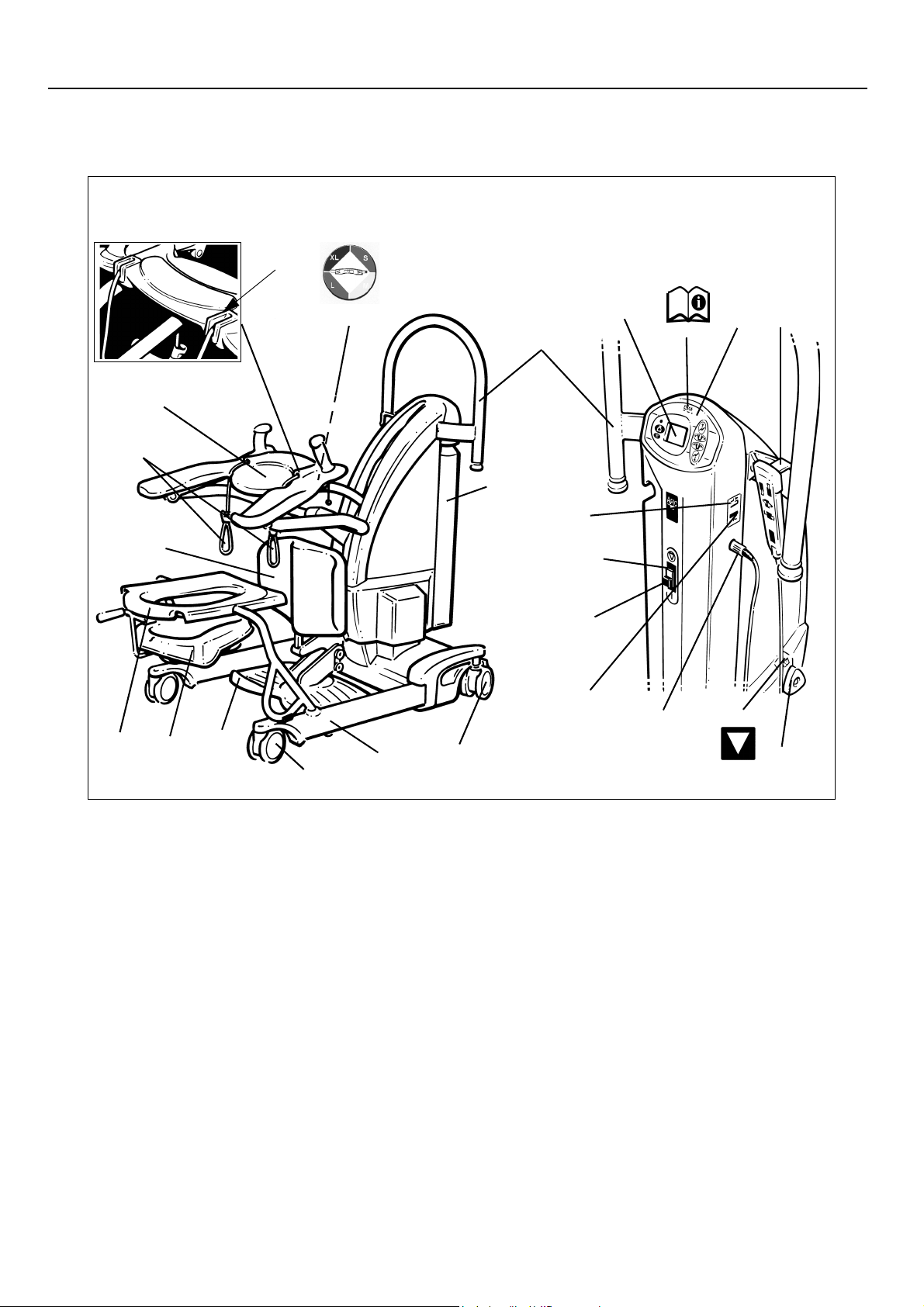
All operations in these instructions are described as
if the attendant were using the control handset. Each
operation described can be controlled using the
control handset and/or the dual switch panel,
situated at the rear of the mast.
The Sara Plus is manufactured to a very high
standard, and primarily designed to assist patients
when standing and toileting, for use as a short
distance patient transfer aid, and for standing and
walking practice.
When used as a standing aid the Sara Plus is
extremely useful for quick easy transfers from one
sitting position to another, and to elevate a patient
for toileting, repositioning, changing of
incontinence pads or wound dressings, standing
practice etc. it is not intended for long periods of
suspension or transportation.
Some information contained in these instructions
may become outdated, due to improvements made
to this product in the future. If you have any
questions regarding these instructions or your lifter,
please contact ARJO or their approved distributor.
Foreword

5
Symbols used adjacent to the text in these
instructions:-
Warning: Means:- failure to understand
and obey this warning may result in
injury to you or to others.
Caution: Means:- failure to follow
these instructions may cause damage to
all or parts of the system or equipment.
•Note: Means:- this is important
information for the correct use of this
system or equipment.
This product has been designed and manufactured
to provide you with trouble free use, however, this
product does contain components that with regular
use are subject to wear.
Warning: SOME OF THESE PARTS
ARE SAFETY CRITICAL TO THE
OPERATION OF THE LIFTER AND
WILL NEED EXAMINING AND
SERVICING ON A REGULAR BASIS
AND MUST BE REPLACED WHEN
NECESSARY. See also “Care of your
Sara Plus” section.
Warning: IMPORTANT: When using
the transfer and walking sling for the
transfer operation the maximum lifting
capacity is 140Kg (308lbs). When using
the same sling for walking practice the
maximum lifting capacity is 190Kg
(420lbs).
Do not exceed these weight limits.
Warning: It is advisable to familiarise
yourself and understand the operation of
the various controls and features of the
Sara Plus as described in “Product
Description/Function” section in this
manual and ensure that any action or
check specified is carried out before
commencing to lift a patient.
INTENDED USE
Sara Plus is a standing and raising aid for short
transfers e.g. raising from bed and transfer to
wheelchair, or from wheelchair to toilet. Sara Plus is
also suitable for walking training when the
footboard and kneepad are removed.
Sara Plus is intended to be used in hospitals, nursing
homes or other health care facilities for the different
categories of residents/patients
Category C, where the resident/patient
"Sits in a wheelchair
"Is able to partially bear weight on at least one leg
"Has some trunk stability
"Is dependent on the caregiver in most situations
"Need mobility-maintaining standing exercises
Or,Category D, where the resident/patient
"Sits in a wheelchair
"Is dependent on the caregiver in most situations
"SARA Plus is the only standing and raising aid
where a resident/patient such as Category D, can
safely be raisied and transferred. The unique support
of the EPS (Extra Postural Support) /BOS sling
makes it feasible.
Sara Plus shall always be handled by a trained
caregiver and in accordance with the instructions
outlined in these Operating and Product Care
Instructions.
Sara Plus is intended to be used with specifically
designed ARJO slings
Lifting operations in these instructions are described
as if lifting a patient from a chair, the same
operations can be performed effectively when
lifting a patient from a sitting position on a bed,
although a second attendant should support the
patient if the patient lacks sitting balance.
Caution: Although manufactured to a
high standard the Sara Plus and
accessories should not be left for extended
periods in humid or wet areas.
Do not under any circumstances spray the
Sara Plus or accessories (excluding
slings) with water e.g. under the shower.
Safety Instructions

6
1. Manoeuvring handle
2. Battery pack
3. Braked castors (rear)
4. Chassis legs
5. Front castors (unbraked)
6. Foot support (removeable)
7. Commode pan (optional)
8. Commode seat and frame (optional)
9. Proactive Pad™ (Adjustable)
10. Sling attachment cords
11. Arc-Rest™ (Supportive arm rests with
handgrips)
12. Detail view of cord locking cleats
13. dual control panel
14. Control handset
15. System failure lower override knob
16. Label - System failure lower override
identification
17. Handset cable connection
18. Battery discharge indicator
19. Reset button (green)
20. Emergency stop button (red)
21. Label - Read operating instructions before use
22. Label - Sling size guide
23. Hour meter
24. Scale display panel (if fitted)
Product Description/Function
Fig. 1
P1331a/2, P1431a, P1224, P1381c
11
10
9
4
1
6
2
3
7
8
17
5
20
19
15
24
21 13 14
23
18
16
12
22
Parts referred to in this manual

7
Unpack the battery pack supplied, and fully charge
it as described in “Battery Charging section”.
When the battery pack is charged, disconnect the
mains power, then remove the pack from the charger
and insert it fully into the Sara Plus battery position,
located at the left hand side of the lifter. Locate the
recess in the bottom of the battery with the
protrusion at the bottom of the battery position then
pivot the battery into position until the retaining
catch operates. Electrical connection is made
automatically.
Ensure that the green reset button situated on the
back of the lifter cover is pressed in. (see inset to
Fig. 1).
Check that the system failure lower override knob is
turned fully clockwise and finger tight, (see Fig. 1).
Ensure that both sling types are available for the
types of lift likely to be encountered when using the
ARJO Sara Plus.
Two types of sling can be used with the Sara Plus.
Standing Sling – a single loop, used for supporting
patients at the toilet, and to aid in the standing
process. The sling has a ‘fleece’ cover for added
comfort, which can be easily removed for cleaning.
Transfer and Walking Sling – A loop sling with
back, buttock and leg support, used for easy and
comfortable transporting of patients over short
distances without the need for the detachable seat
frame. By using different attachment straps the
same sling can be used for supporting patients
during the training procedure of standing, stepping
and walking under the supervision of trained
nursing staff. The sling has variable adjustment.
Note: The slings have colour coded connection
loops for size identification, as follows:-
Red - Small (S)
Yellow - Medium (M)
Green - Large (L)
Blue - Extra Large (XL)
A circular label is fitted to the central lifting tube for
quick colour to size reference. (see fig 1)
Controls and Features
Control handset:- Is a semi-remote control unit
attached to the lifter by an extending cable. The
handset controls lift and lower and chassis leg
opening/closing. Direction arrows adjacent to the
buttons indicate each function. (See Fig. 2). If
pressure is released from any button during use,
powered movement will stop immediately.
Fig. 2
P1396a
‘Raise’ button ‘Lower’ button
‘Chassis legs
open’ button ‘Chassis legs
close’ button
Dual control panel:- offers the same controls as
the handset and is conveniently positioned on the
top of the main body of the lifter (See Fig. 3).
Fig. 3
P1431b
Emergency stop button (red):- (see fig 1) If, in an
emergency, you have to immediately stop any
powered movement, (other than by releasing
pressure on the button either on the handset or dual
control panel), press the “emergency stop button
situated on the back of the cover below the dual
control panel. (See Fig. 1).This function can also be
utilised to ensure that no powered operation is
accidentally used when either transporting the lifter,
or leaving the lifter in store or unattended.
Product Description/Function

8
Once the emergency stop button has been operated,
the green reset button will have to be re-engaged by
pressing it in, before any powered movement can be
utilised.
Reset button (green):- (see Fig. 1) Adjacent to the
emergency stop button. It is used to reset the ‘power
on’ condition, once the emergency stop button has
been operated, also used to reset if the automatic
overload fuse has operated (indicated by the reset
button projecting outwards slightly). If the fuse has
operated and once reset, operates again, withdraw
the lifter from use and contact ARJO Service
department or their appointed distributor.
Automatic cut out:- (not an operator control but a
function built into the lifter electronics):-
If the lifter is inadvertently overloaded (trying to lift
a patient heavier than permitted), an automatic ‘cut
out’ operates to prevent the lifter raising a load in
excess of one and a half times the maximum rated
load; this will stop the lift motion automatically.
If this occurs, when pressure is released from the lift
button on the handset or dual control the electronics
will reset and enable the patient to be lowered only,
by pressing either lower button. Remove the patient
from the lifter.
Automatic stop function:- Great care should be
taken not to lower the patient support arms onto the
patient or any other obstruction but if this should
happen inadvertently the motor will continue to run
but downward movement will be held by the
obstruction. If this occurs release pressure from the
‘lower’ button immediately, operate the ‘raise’
button until clear, then remove the obstruction.
System failure lower override:- This can be used
in the event of main control failure. In the unlikely
event that the control handset or dual control panel
fails to operate the lifter, with a patient still
supported by the sling, provision for lowering has
been made, using the “lower override knob”,
situated on the right hand side of the main cover (see
Fig. 4). A label situated above the switch is for quick
and easy recognition (see Fig. 1) To operate the
lower override, turn the knob anti clockwise half a
turn, to cease lowering turn the knob clockwise until
finger tight only (do not over tighten), only use this
knob in the event of normal control failure do not
use it for normal function lowering.
Warning: Before operating the lower
override to lower a patient, always ensure
that a chair or suitable support is
underneath ready to accept the patient.
Fig. 4
P1332c
The lower override will operate whether the
emergency stop button has been operated or not.
The “automatic stop function” of the jib will still
operate when using the lower override knob.
When using the Sara Plus normally, always ensure
the system failure lower override knob is always
turned fully clockwise and finger tight.
Battery Discharge Indicator:- is a small LED
display which shows the charge condition of the
lifter battery. (See Fig. 1 and also ‘Battery Charging
Section’ for complete description).
Hour Meter:- Is a small LCD display (See Fig. 1)
which shows the total duration of powered
operation (in hours). This is primarily intended as an
aid to service engineers and to help the attendant
calculate servicing intervals.
Chassis castor Brakes:- The chassis rear castors
have brakes which can be foot operated if required,
(see Fig. 5) for example, when leaving the patient
unattended, or to keep the Sara Plus in position.
Straight line steering function :- When using the
Sara Plus for walking practice it may be considered
useful to fix one of the castors to steer in a straight
line. This has the effect of allowing the Sara Plus,
without assistance to follow the intended straight
line walked by the patient. The function is activated
by flipping over the steering guide on the rear castor
to hold it in position (see Fig. 5).
P1332e, f
Fig. 5
Straight line
steering guide
Product Description/Function

9
Arc-Rest (with handgrips):- Integral Part of the
Lifting mechanism of the lifter, the intuitive and
supportive armrests allow patient participation and
comfort during the lifting procedure. (See Fig. 1)
Foot Support:- For positioning the patient’s feet
when lifting and transporting, it can be removed if
using the Sara Plus to lift a patient to their feet prior
to them using a walking aid eg. “Zimmer” etc. To
remove the foot support, raise the Proactive knee
support to its highest position, (note: where
installed, unclip one side of the “Velcro” tie strap
from around the foot support cover and slide the
cover up the knee support column). Position
yourself between the chassis legs and grip both sides
of the foot support, lift up the front half of the foot
support until it just comes into contact with the foot
support bracket (see fig. 6), whilst it is in this
position pivot the rear of the foot support upwards
until the foot support is horizontal. Pull the foot
support towards yourself until it is clear of the
support bracket. Store carefully for future use.
Slide the foot support cover back down into position
and secure using the “Velcro” strap. Re-adjust the
Proactive kneepad to the position required.
Re-fitting the foot support is acheived by reversing
the above procedure. Note: Ensure the two hooks on
the foot support locate over the top two locating
buttons.
Fig. 6
P1450
Proactive Pad™:- This is a reactive lower leg
support Fig. 1 and 7), which enables the patient to be
lifted comfortably and effortlessly. It can be
adjusted vertically for differing lower leg lengths
and is sprung to stay in contact, when the patient’s
legs move radially during the lifting procedure. To
adjust, hold the Proactive Pad™with one hand (see
Fig. 7) and slacken the clamping screw knob with
the other hand. When the correct height has been
established re-tighten the knob.
Fig. 7
P1334c/2
Proactive Pad™clamping
screw knob
Proactive Pad™
It can be removed from its mount quickly, for
walking practice, simply by lifting upwards, after
the foot support has been removed.
Lower leg Straps:- An optional accessory used for
ensuring the lower parts of the patient’s legs stay in
close proximity to the Proactive Pad™ for correct
lifting procedure.
The Strap ensures the lower parts of the patient’s
legs stay in close proximity to the Proactive Pad for
correct lifting procedure. The strap is held in
position in relationship to the Proactive Pad by
passing through the guides on the back of the
Proactive Pad then around the patients lower calves
to be finally overlapped and pressed together to join
the “velcro” fastening. (See Fig. 8). Ensure the strap
is firm but comfortable for the patient
.
Fig. 8
P1333a/2
Product Description/Function

10
Adjustable width chassis legs:- By operating the
appropriate button on either the control handset or
dual control panel on the lifter the chassis legs can
be opened to any variable width (See Fig. 9). When
pressure is released from the button, movement will
stop and the chassis legs will remain securely in
position.
•Note: Transportation should be
done with the chassis legs closed, it will
be easier through doorways etc.
Fig. 9
P1332d
Warning: At all times the patient and/or
operator should not allow their feet or any
other part of their body to be placed in the
area between the foot support and chassis
legs when the chassis legs are closing.
Commode Seat (Accessory)
For toileting patients at the chair or bedside or for
patients who cannot be transported with the transfer
sling, the use of the commode seat and frame is the
recommended method of transporting patients over
longer distances. The commode frame is inserted
into the holes in the chassis legs (see Fig. 10), once
the patient has been lifted to a standing or near
standing position in the manner previously
described.
Fig. 10
P1335d/2
Removal of any clothing can be attended to, and the
patient is then lowered down onto the commode
seat. It is recommended that the patient is kept
supported by the sling.
The retractable commode pan, accessible from the
rear of the seat, (see Fig. 11), may be utilised, or
removed to enable the patient to be positioned over
a toilet. Apply chassis brakes if leaving the patient
unattended.
Fig. 11
P1335e
Product Description/Function

11
Using the Sara Plus for Toiletting
and Transporting
Before approaching the Patient the attendant should
always tell the patient what they are going to do, and
have the correct size and type of sling ready. (See
description of sling types in the “Introduction”
section.)
Although the sling can be fitted to the patient with
the Sara Plus in close proximity it may be
considered easier to fit the sling to the patient with
the Sara Plus away.
Once the sling has been fitted (see following
sections) the Sara Plus may be brought to the patient
as follows:-
Adjust the height of the Patient Support arms to be
raised or lowered sufficiently to avoid approaching
the patient at eye level, making allowances for the
patients arms and any obstructions, e.g. chair arms
etc.
Approach the patient from the front with the lifter,
stop before the foot support and Proactive Pad™ are
in contact with the patient. (See Fig. 12)
Fig. 12
P1334a/2
•Note: If required, the chassis legs
may be opened to go around the chair, by
operating the appropriate button on the
control handset or dual control on the
lifter.
•Note: If the handset button or dual
control button is released during any
function, powered motion will stop
immediately.
•Note: If the handset button or dual
control button is released during any
function, powered motion will stop
immediately.
When the patient is ready, give assistance or allow
the patient to place his/her feet on the foot support,
pushing the Sara Plus towards the patient a little to
achieve this easily. (See Fig. 13).
Fig. 13
P1334b/2
Adjust the Proactive Pad™ height (if necessary) –
an approximate guide is to align the top of the
Proactive Pad™ just below the patient’s patella.
(See Fig. 14).
Fig. 14
P1334g/2
Carefully push the lifter in closer to make full lower
leg contact with the Proactive Pad™ (see Fig. 15),
then apply the chassis brakes.
Fig. 15
P1331e/2
For the use of each individual type of sling see
following sections: -
Using your Sara Plus

12
Standing Sling
Warning: Assessment will have to be
made whether the patient requires the
lower leg straps, apply if necessary.
Allow the patient to hold the handgrips, with their
arms resting on the Arc-Rest. This will not apply if
fitting the sling around the patient before the Sara
Plus is brought into close proximity.
Encourage the patient to lean slightly forwards to
enable the sling to be placed around the lower back
of the patient (see Fig. 16). Position the sling around
the patient’s back so that the bottom of the sling lies
horizontally approximately two inches above the
patient’s waistline, with the patient’s arms outside
the sling. Ensure the support strap is separated,
brought loosely around the body, and is not twisted
or trapped behind the patient’s back.
Fig. 16
P1333b
Fasten the support strap securely by overlapping
and pressing the “Velcro” together. The strap should
be tight, but comfortable for the patient. (See Fig.
17).
•Note: As stated previously, the
standing sling may be applied before the
Sara Plus is brought into position as
shown in figure 13.
Warning: The support strap must
always be applied when using any of the
slings.
•Note: The support strap will assist
in supporting the patient in the sling
during the lifting procedure. The strap
also retains the sling in the correct
position around the patient.
Fig. 17
P1333c
If the Sara Plus is not already in close proximity to
the patient bring it to the patient as described
previously.
Take each adjustment cord in turn and attach to the
sling. (See Fig. 18).
Fig. 18
P1333d, e, f
Fitting the Loop Lock cord attachment system
Cone
‘Cup’ section
Using your Sara Plus

13
When both cords are attached correctly make
adjustments on both cords equally so that any slack
is taken up in each cord and the back section of the
sling supports the patient comfortably and securely,
lock the adjustment cords down into the cord
retaining cleats. (See Fig. 19).
Warning: Ensure the cord end knobs are
away from the proactive pad™ when the
patients legs are near or in contact with the
pad.
Fig. 19
P1331b/2, P1381b
Detail view showing cords & cleats
•Note: The patient should be
supported by the sling, but not pulled
forward too much. (See Fig. 20)
Fig. 20
P1334e/2
If possible, the patient should then hold on to the
Patient Support arms with one or both hands.
The patient is then ready to be lifted.
•Note: If the handset button or dual
control button is released during lifting
or lowering powered motion will stop
immediately.
If the patient is able to offer some assistance when
standing this may be beneficial to patient
confidence and muscular exercise. Encourage the
patient to assist all he/she can to raise from the chair
and/or steady themselves.
Operate the lift button on the handset or dual control
panel to raise the patient to a suitable and
comfortable height for the particular function, e.g.
transportation, toileting with commode, etc. (See
Fig. 21)
Fig. 21
P1334f/2
IMPORTANT: Always check that the sling
adjustment cords are fully in position and locked
before and during the commencement of the lifting
cycle, and in tension as the patient’s weight is
gradually taken up.
•Note: If the patient can stand
sufficiently well and lock his/her knees in
the normal way when fully raised, their
knees will come away from the Proactive
Pad™ and he/she will be able to lean
back into the sling.
Patients who can only hold on with one hand, (those
who have suffered a “stroke”, for example) may still
be lifted by using the Sara Plus. The patient may
just rest the unusable arm on the Arc-Rest or hold it
across their chest, and rest their elbow on the end of
the Arc-Rest, while their useable hand holds the
handgrip in the normal way.
Using your Sara Plus
Warning: Ensure the cone is pulled
tightly into the cup section. (See Fig. 18).

14
If required insert the detachable seat frame into the
receptor holes in the chassis legs, then lower the
patient to a comfortable seating position for
commode toiletting or longer distance
transportation. (See Fig. 22).
Fig. 22
PP1331e/2
•Note: The chassis legs will have to
be adjusted to the closed position to fit
the seat frame.
Release the brakes, and transfer the patient to new
position, i.e., toilet, wheelchair, chair, bed, etc.
•Note: Transportation should be
done with the chassis legs closed, it will
be easier through doorways etc.
While the patient is raised, make any necessary
adjustments to clothing, incontinence pads etc.,
before lowering again. Lower the patient carefully
using the control handset or dual control panel.
Warning: Apply the chassis brakes if
leaving the patient at the toilet, or if
leaving the patient unattended.
When the patient is seated in the new position, and
you wish to remove the sling.
Pull each cord up from the locking cleats and
slacken the cords sufficiently to release the Loop
Lock™ fitting, then remove the cords from the
sling.
Pull apart the “Velcro” fastening to remove the
support strap.
Warning: Do not attempt to release the
support strap while the patient is
supported by the sling.
Remove the sling from the patient.
Remove the lower leg straps if they have been
applied.
Warning: If the patient lacks sitting
balance and has been returned to sit on the
side of the bed a second attendant may be
needed to support the patient while the
sling is being removed.
Transfer and Walking Sling
Using the sling for transfer (140Kg - 308 lbs
maximum patient weight):- The attendant should
always tell the patient what they are going to do, and
have the correct size and type of sling ready. (See
description of sling types in the “Introduction”
section.)
Encourage the patient to lean slightly forwards to
enable the selected sling to be placed around the
lower back of the patient (see Fig. 23). Position the
sling around the patient’s back so that the bottom
edge of the sling is level with the base of the spine.
Ensure the patient’s arms are outside the sling and
that the support strap is separated.
Take each leg section of the sling in turn and slide
under each leg, (see Fig. 24).
Bring the support strap around the body and fasten
securely by overlapping and pressing the “Velcro”
together.
Fig. 23
P1337a
Take each leg section of the sling in turn and slide
under each leg, (see Fig. 25).
Using your Sara Plus
Warning: Only use this or other
methods after a satisfactory professional
assessment has been carried out on the
individual patient.

15
The strap should be tight but comfortable for the
patient. (See Fig. 26).
Fig. 26
P1334a/2
•Note: If required, the chassis legs
may be opened to go around the chair, by
operating the appropriate button on the
control handset or dual control on the
lifter.
•Note: If the handset button or dual
control button is released during any
function, powered motion will stop
immediately.
Give assistance or allow the patient to place his/her
feet on the foot support, pushing the Sara Plus
towards the patient a little to achieve this easily.
(See Fig. 27).
Fig. 27
P334b/2
Adjust the Proactive Pad™ height (if necessary) - to
align the top of the Proactive Pad™ just above the
patients patella, or adjust the pad to its highest
position. (see Fig. 28).
Using your Sara Plus
Fig. 24
P1337b
•Note: The support strap will assist
in supporting the patient in the sling
during the lifting procedure.
Fig. 25
P1337d

16
Identify the attachment loop on each side of the
sling and attach the right hand adjustment cord to
the left loop, repeat for the other side (see Fig. 29).
See also Fig. 18 for attachment of the cords.
Fig. 29
P1337c
When both cords are attached correctly make
adjustments on both cords equally so that any slack
in the cord is taken up.
Warning: Lock the adjustment cords
down into the cord retaining cleats (see
also Fig. 30).
Warning: Ensure the cord end knobs are
away from the proactive pad™ when the
patients legs are near or in contact with the
pad.
Fig. 30
P1338a, P1381b
Detail view showing cords & cleats
Identify the support strap on each side of the sling
(fitted with a plastic attachment clip), and adjust
both straps to their maximum length. Attach each
clip to the lug situated on the outer sides of the Arc-
Rest (see Fig. 31).
P1338b
Fig. 31
Warning: Ensure each clip is attached
correctly and secure onto the lug.
Allow the patient to hold the hand grips with their
arms resting on the Arc-Rest.
Operate the lift button on the handset or dual control
panel, continue to raise until each support strap is in
tension and the patient’s back just comes away from
the chair, then stop the lift. Then adjust both cords
equally to take up any slack, lock both cords into the
locking cleats. (See Fig. 32).
Continue raising until the patient is just clear of the
seat.
Using your Sara Plus
Fig. 28
P1334d/2

17
If any discomfort is experienced by the patient
return to the sitting position and re-adjust.
Warning: Important: Always check
that the sling adjustment cords and
support strap attachment clips are fully in
position and locked before and during the
commencement of the lifting cycle, and in
tension as the patients weight is gradually
taken up.
Be careful not to raise the patient too high as this
will negate the comfort of the transfer sling.
Release the chassis brakes and close the chassis
legs, then transport the patient to desired
position.(See Fig. 33).
Fig. 33
P1338d
Transportation should be done with the chassis legs
closed, it will be easier through doorways etc.
Warning: Apply the chassis brakes if
leaving the patient unattended.
Do not attempt to release the straps or
cords while the patient is supported by the
sling.
Using the sling for walking practice - (190Kg -
420 lbs maximum patient weight):-
Remove the foot support from the lifter and store
carefully for future use (see “Product Description/
Function” section in this manual).
As with all types of lift, before approaching the
patient the attendant should always tell the patient
what they are going to do, and have the correct size
and type of sling ready.
Encourage the patient to lean slightly forwards to
enable the selected sling to be placed around the
lower back of the patient (see Fig. 23). Position the
sling around the patient’s back so that the bottom
edge of the sling is level with the base of the spine.
Ensure the patient’s arms are outside the sling and
that the support strap is separated. Bring the support
strap around the body and fasten securely by
overlapping and pressing the “Velcro” together. The
strap should be tight but comfortable for the patient.
•Note: The support strap will assist
in supporting the patient in the sling
during the lifting procedure.
Take each leg section of the sling in turn and slide
under each leg (See Fig. 25).
Pull up each leg section strap and connect to each
corresponding body strap, by connecting both
halves of the buckles securely (see Fig. 34).
P1339d
Fig. 34
Adjust the straps to be supportive but not restrictive
for the patient. (See Fig. 35).
•Note: The leg section strap
connection can be performed after the
patient has been lifted if preferred.
Using your Sara Plus
P1338c
Fig. 32

18
Adjust the height of the Arc-Rest to be as low as
possible, making allowances for obstructions, e.g.
Chair arms etc.
Approach the patient from the front with the lifter;
stop before the Proactive Pad is in contact with the
patient. (See Fig. 36).
Fig. 36
P1331d/2
•Note: If required, the chassis legs
may be opened to go around the chair, by
operating the appropriate button on the
control handset or dual control on the
lifter.
•Note: If the handset button or dual
control button is released during any
function, powered motion will stop
immediately.
Adjust the Proactive Pad height (if necessary) - an
approximate guide is to align the top of the
Proactive Pad just below the patient’s patella. (See
Fig. 28).
Carefully push the lifter in closer to make full lower
leg contact with the Proactive Pad, then apply the
chassis brakes.
Identify the cord attachment loop on each side of the
sling body and attach the cords (Loop Lock method
as previously shown in Fig. 18). When both cords
are attached correctly adjust both cords equally so
that the slack is taken up, but does not pull the
patient forward.
Warning: Lock the adjustment cords
down into the cord retaining cleats. (See
Fig. 37).
Fig. 37
P1339a, P1381b
Detail view showing cords & cleats
Allow the patient to hold the handgrips with their
arms resting on the Arc-Rest.
Slacken the adjustment on each body support strap
(if required), enough to be able to connect the
attachment clips to the lugs on the outer sides of the
Arc-Rest (See Fig. 38).
P1339c, P1381a
Detail view of
strap attachment
Fig. 38
Using your Sara Plus
Fig. 35
P1339e

19
When the patient is ready, operate the lift button on
the handset or dual control to raise the patient, at the
same time encourage him/her to actively stand (See
Fig. 39).
P1339b
Fig. 39
Continue to raise the Arc-Rest until the patient is in
a comfortably supported standing position (see
Fig. 40).
P1339f
Fig. 40
If walking practice is to be carried out ensure the
patient is correctly and comfortably supported,
adjust the body support straps equally to take up any
slack and be supportive but not too tight and make
adjustment to the Arc-Rest as necessary.
When the patient is standing confidently release the
brakes and pull the lifter slightly away from the
patient until the Proactive Pad is clear of the patients
legs (see Fig. 41).
Re-apply the chassis brakes then carefully remove
the Proactive Pad complete with attachment bracket
by lifting upwards and store carefully for future use.
(See Fig. 42).
Fig. 41
P1340a
Fig. 42
P1340b
•Note: The chassis legs may be
opened or left open to give better
clearance for the patient.
•Note: The ‘straight line’ steering
lock (if fitted) can be applied over the
rear castor as an additional aid if
required.
With the Pro-Active pad removed and the brakes
released, the patient will be able to walk at their own
pace, while being supported by the Sara Plus. (See
Fig. 43).
Using your Sara Plus

20
Once walking practice has been completed, apply
the chassis brakes and replace the Pro-Active pad,
return the patient to a chair and when fully
supported, remove the sling by reversing the fitting
procedure.
ARJO Scale (if fitted)
If your Sara Plus has been supplied with the integral
Scale unit (see Fig. 44), it is possible to weigh a
patient during the lifting procedure.
The scale has been designed to weigh hospital or
care facility patients under the supervision of
trained nursing staff. All other uses must be
avoided.
Reset Button (lbs to kg) Scale operating
button
Visual display
Print out button
(if facility is fitted) Fig. 44
mP1431c
Scale Labels
On the labels relating to the Scale you will find the
following information:-
Rating and Battery Size Label
(attached to the plate behind the lifter battery)
Weight range 1 = 2kg - 120kg (4lbs - 264.6lbs)
d = e 100g (0.2lbs)
Weight range 2 = 4kg - 190kg (10lbs - 419lbs)
d = e 200g (0.5lbs)
d = Actual Scale Division
Serial number label
(attached to the plate behind the lifter battery)
Using your Sara Plus
Fig. 43
P1340c
•Note: To have better flexion for the
leg it may be necessary to slacken the leg
straps slightly, this will allow better leg
movement.
Warning: Do not separate the two
halves of the buckles or release the
adjustment cords at any stage other than
when the patient is seated and fully
supported.
Ensure there are no obstructions in the path
before the patient is encouraged to walk.
Other manuals for SARA PLUS
2
Table of contents
Other Arjo Medical Equipment manuals

Arjo
Arjo AtmosAir User manual

Arjo
Arjo MaxxAir ETS User manual

Arjo
Arjo Sorrento Floor Bed User manual

Arjo
Arjo MAXI MOVE Operating instructions

Arjo
Arjo Alpha Active 3 User manual

Arjo
Arjo Sara 3000 User manual

Arjo
Arjo Auralis User manual

Arjo
Arjo Maxi Sky 440 User manual

Arjo
Arjo FIRST STEP User manual

Arjo
Arjo TheraRest User manual

Arjo
Arjo Rik Overlay User manual

Arjo
Arjo Miranti User manual

Arjo
Arjo Flowtron Excel User manual

Arjo
Arjo Typhoon User manual

Arjo
Arjo Enterprise ENT-ACC02 User manual

Arjo
Arjo Enterprise ENT-ACC06 User manual

Arjo
Arjo LGMAT/13 User manual

Arjo
Arjo Maxi Air User manual

Arjo
Arjo Prioma User manual

Arjo
Arjo Enterprise ENT-ACC24 User manual