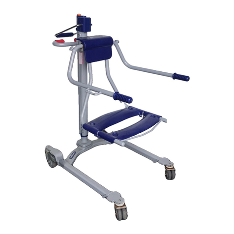
Arjo MAXI MOVE Operating instructions

MAXI MOVE
TM
Maintenance and
Repair Manual
001.25075.EN_rev0
July 2008

© ARJO International AB 2008
ARJO products are patented or patent pending. Patent
information is available by contacting ARJO International AB.
Our policy is one of continous development, and we therefore
reserve the right to make technical alterations without notice. The
content of this publication may not be copied either whole or in
part without the consent of ARJO International AB.

3
Safety Instructions ...........................................................................5
General .............................................................................................................. 5
Product and Technical Description ...............................................6
Introduction ....................................................................................................... 6
Features ............................................................................................................. 6
Combi Feature ................................................................................................... 6
Risk Assessment Checklist for Engineers ......................................................... 7
Suggested Tools ................................................................................................ 8
Recommended Spares ....................................................................................... 8
Loctite Application ............................................................................................ 9
Torque Data and Consumable Materials ........................................................... 10
Preventive Maintenance Schedule .................................................12
Service Procedures ..........................................................................17
Procedures not Included in the PMS ................................................................. 17
Service Procedure 1 ........................................................................................... 18
Check that the latest updates have been implemented ................................ 18
Service Procedure 2 ........................................................................................... 19
Check the battery ......................................................................................... 19
Battery test ................................................................................................... 19
Check the battery charger ............................................................................ 20
Service Procedure 3 ........................................................................................... 21
Check all vital parts for corrosion and damage ........................................... 21
Painting ........................................................................................................ 21
Service Procedure 4 ........................................................................................... 22
Full Feature Test .......................................................................................... 22
Service Procedure 5 ........................................................................................... 23
Safe Working Load Test (local Requirement) ............................................. 23
Service Procedure 6 ........................................................................................... 26
Scale Calibration Check .............................................................................. 26
Verified Scale ........................................................................................26
Verified Scale and Non-Verified Scale ................................................. 26
Service Procedure 7 ........................................................................................... 27
Wheel Replacement .....................................................................................27
Front ...................................................................................................... 27
Back ....................................................................................................... 28
Service Procedure 8 ........................................................................................... 29
Changing the Leg Assembly/Actuator ........................................................ 29
Chassis opening ..................................................................................... 29
Legs ........................................................................................................ 29
Legs Actuator .........................................................................................29
Reassembly ............................................................................................30
Service procedure 9 ........................................................................................... 31
Legs opening adjustment ............................................................................. 31
Verification ............................................................................................ 31
Adjustment ............................................................................................. 31
Service Procedure 10 ......................................................................................... 32
Control box (PCB, Fuse, Switch, Keypad) .................................................. 32
Opening the Control box ........................................................................ 32
Fuse change ............................................................................................ 32
Main board changes ............................................................................... 32
DIP Switch Settings ..................................................................................... 34
Configuration procedure ........................................................................ 34
Changing the Brake board ..................................................................... 36
Table of Contents
4
Table of Contents
Changing the Switch ............................................................................. 36
Closing the control box .......................................................................... 37
Service Procedure 11 ......................................................................................... 39
Replacing the Handset .................................................................................39
Service Procedure 12 ......................................................................................... 40
Replacing the Maxi Move Strap .................................................................. 40
Strap removal .........................................................................................41
Top Cover reassembly ........................................................................... 44
Verification ............................................................................................ 45
Service Procedure 13 ......................................................................................... 46
Replacing the Mast Actuator ....................................................................... 46
Removing the Mast ............................................................................... 46
Removing the Actuator .......................................................................... 47
Installing the Mast ................................................................................. 48
Service Procedure 14 ......................................................................................... 49
Replacing/Adjusting the Handle .................................................................. 49
Removing the Handle ............................................................................ 49
Replacement ...........................................................................................50
Adjustment ............................................................................................. 50
Service Procedure 15 ......................................................................................... 51
Changing the Limit Switch .......................................................................... 51
Anti-crush / Lower Limit ....................................................................... 51
Upper limit ............................................................................................. 52
Service Procedure 16 ......................................................................................... 54
Slider Adjustment Replacement .................................................................. 54
Adjusting Sliders .................................................................................... 54
Upper slider ........................................................................................... 54
Lower slide ............................................................................................ 55
Replacing Sliders ......................................................................................... 55
Service Procedure 17 ......................................................................................... 56
Jib / Jib roller / Jib cover ............................................................................. 56
Jib removal ............................................................................................. 56
Jib Reinstallation ....................................................................................56
Jib roller change .....................................................................................56
Changing the Jib Top Cover .................................................................. 57
Service Procedure 18 ......................................................................................... 58
Combi Attachment ....................................................................................... 58
Inspection ............................................................................................... 58
T-Bar removal ........................................................................................ 59
T-Bar installation ................................................................................... 59
Service Procedure 19 6....................................................................................... 0
Scale Removal/Installation .......................................................................... 60
Removing the Scale ............................................................................... 61
Installing the Scale ................................................................................. 61
Service Procedure 20 ......................................................................................... 62
Combi Spreader Bars ...................................................................................62
Stretcher ................................................................................................. 62
Four-Point DPS Pivot Point ................................................................... 63
Four Point DPS (Combi) ............................................................................. 63
Four-Point Powered DPS Spreader Bar ...................................................... 64
Sling Checks ................................................................................................ 66

5
Safety Instructions
General
A. ARJO strongly advise that only ARJO designated parts, which are designed for the purpose,
should be used on equipment and other ARJO supplied appliances to avoid injuries attributable
to the use of inadequate parts. ARJO’s conditions of sale make specific provision confirming
no liability in such circumstances. Our policy is one of continuous development, and we
therefore reserve the right to change specifications without notice.
B. Unauthorized modifications on any ARJO equipment may affect its safety and are in breach
of any warranty on it. ARJO will not be held responsible for any accidents, incidents or lack of
performance that occur as a result of unauthorized modifications to its products.
C. If the terms listed below are used in the text their meaning is as follows:
D. Dangerous substances. If using hazardous substances be sure how to handle these and refer
to applicable information. In doubt refer to the local authorities for health and safety
requirements.
DANGER
Means: Electrical hazard warning, failure to understand and obey may result in electrical
shock.
WARNING
Means: Failure to understand and obey may result in injury to you or to others.
CAUTION
Means: Failure to follow these instructions may cause damage to all or parts of the system or
equipment.
NOTE
Means: This is important for the correct use of this system or equipment.

6
Introduction
The Maxi Move is a mobile patient lifter and is used for transferring patients from bed or chair
to the toilet or bath. The floor lift has a maximum safe working load (SWL) of 227 kg (500 lb).
Each Maxi Move is supplied with two 24V rechargeable batteries and a charging unit.
Features
The features of the Maxi Move floor lift include:
• Immediate stop/reset switch
• Overload circuit
• Overload current limit protection in the PCB
• Upper limit switch
• Lower limit switch/anti-crush
• Control panel on the unit
• Emergency manual wind down
• Handset LCD display
• Audible low-battery warning
The raising and lowering mechanism comprises an electromechanical linear actuator powered
by a 24VDC motor.
The leg opening and closing mechanism comprises a 24VDC motor and a double-ended
actuator (legs open independently).
Combi Feature
The Maxi Move with the ‘Lock & Load’ (combi attachment) has the facility to accommodate:
• A two-point spreader bar for use with a loop sling to support patients with contracted
(restricted movement) or ‘windswept’ (deformed) limbs and walking slings.
• A two-point loop small.
• A two-point loop medium.
• A four-point loop large.
• A four-point spreader bar Dynamic Positioning System (DPS) for general lifting (small,
medium and large).
• A 4 point powered spreader bar Dynamic Positioning System (DPS) for general lifting
(medium and large).
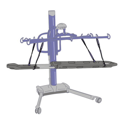
• A stretcher system for handling dependent, fragile patients with a minimum of
disturbance (SWL 160kg (350 lb)).
NOTE: The SWL will depend on the lift’s configuration and attachments. Always refer
to the maximum SWL of the lowest rated attachment.
Product and Technical Description

7
Product and Technical Description
Risk Assessment Checklist for Engineers
The following assessment MUST be made before carrying out servicing, repair work or
installations:
• Make sure the work area is adequately sized, suitably lit and at a reasonable temperature.
• The floor surfaces must be free from clutter, unevenness and non-slip.
• Use good engineering and manual handling practices to keep risk of injury at its lowest
level.
• Tools and equipment must be kept in good condition.
• Wear protective clothing and eye protection where necessary.
• You should be adequately trained to perform the task.
• Do not manually lift items that could cause personal injury, that is too heavy, hot or
sharp.
• You must comply with all local site safety rules, report any incident or accident to the site
safety supervisor or equivalent. Use the ARJO reporting procedure.
• If necessary use Hard Surface Wipes (Alcohol Impregnated) to decontaminate a machine
before carrying out any work.
• Load tests must only be applied as instructed in the relevant procedure.
• If it is necessary to work from a platform (i.e. scaffold, ladders etc.) to perform a service
or installation task make sure the platform is secure and suitable for the task.
• Do not perform maintenance tasks on equipment with ‘live’ electrical connections unless
absolutely necessary.
• Isolate the power supply before removing plugs, sockets or disconnecting cables.
• Be alert at all times to the dangers of working on electrical equipment that operates on
mains supply voltage. Where possible, visually inspect electrical cables and plugs etc. for
damage or deterioration before working on equipment.
• Dispose of all waste in appropriate containers.
WARNING: IF IN DOUBT, CONTACT YOUR LOCAL ARJO REPRESENTATIVE. DO
NOT TAKE UNNECESSARY RISKS.
NOTE: The above wipes should be of the type that has proven bactericidal action for
disinfecting hard surfaces against MRSA & E.COLI.
DANGER – Electrical Shock can kill.

8
Product and Technical Description
Suggested Tools
• Standard tool kit.
• Special Tool ST252.
• 2 x 20kg weights ST219.
• Socket Allen key: (4mm ST82) (5mm ST274) (6mm ST55) (8mm ST87).
• Drift ST288.
• Ball-end Allen key (4mm) ST292.
• Starlock Washer Installation Tool (ST295).
• Sling Clip Gauge ST331.
• Load Test Equipment: refer to Section 11.0.
Recommended Spares
Refer to PARTS LIST 001.25070.EN
NOTE: This manual is intended to be used in reference to the Maxi Move
manufactured in Canada (Serial number KMCXXXXX).
For the Maxi Move manufactured in the UK or in Sweden, please refer to:
09.MKM.00/3GB

9
Product and Technical Description
Loctite Application
Refer to the manufacturer instructions on the container before use, in addition to the following
information:
Procedure for the correct use of Loctite 242 and Loctite 243 (Colour blue) Threadlocking:
- Clean both of the joint faces with Loctite 7063 Cleaner or a lint-free cloth
moistened with Acetone or another suitable volatile solvent.
- Apply Loctite 243 sparingly but sufficient to fill all engaged threads. (This
product performs best in thin bond gaps [0.05 mm]).
- Install the threaded components and where known, torque to the applicable
torque figure. If the torque figure is not known tighten to a firm fixing.
- Clean off any unwanted adhesive.
- Allow the Loctite 243 to cure before subjecting to load.
- Where the cure speed is unacceptably long, or large gaps are present,
applying Loctite Activator ‘N’ or ‘T’ to the surface will improve the cure
speed.
For general Loctite specifications and application details: refer to Loctite manufactures
instructions.
NOTE: Because Loctite 243 is oil-tolerant, it is not necessary to meet the same
standard of oil-free cleanliness as for Loctite 242.
NOTE: The cure time will depend on the materials used, the ambient temperature
and the bond line gap.

10
Product and Technical Description
Torque Data and Consumable Materials
Thread retaining: Apply Loctite 243 when no threadlocking patch has been pre-applied. When
replacing a part with pre-applied threadlocking, the part should be replaced by a new part using
pre-applied threadlocking.
Fig.1
NOTE: Grease 005.00031: Lenson white
grease or equivalent can be used.

11
Product and Technical Description
Fig.2

KEY: X= Action required on the part of the customer S= Action required on the part of a qualified service technician
12
Action
DPS Spreader Bars Loop Spreader Bars
Manual Powered 2-4 Point Stretcher
Before
Every Use
Every
Week
Every 12
Months
Every 2
Year s
Before
Every Use
Every
Week
Every 12
Months
Every 2
Year s
Before
Every Use
Every
Week
Every 12
Months
Every 2
Year s
Before
Every Use
Every
Week
Every 12
Months
Every 2
Year s
Visually inspect the condition of all
sling attachment points for damage. If
any is found, replace with new unit.
XXXX
Make sure all instruction labels are
attached and readable. Replace as
required. See “Operating Instructions”
for location of labels.
XXXX
Check the condition of the friction discs
and bushes within the pivot points. If
found worn and/or damaged, parts must
be replaced.
SS
When the friction discs and bushes have
been checked/replaced, reset friction
assembly to support a 5.4 kg (12 1b)
load at the handle.
SS
Visually inspect all external parts,
making sure no damage has occurred
during use. Replace parts as required.
SS
Make sure the unit can be powered
through the full range smoothly.
S
Examine all exposed parts, especially
where there is close contact with the
patient’s body. Make sure no cracks or
sharp edges have developed that could
cause injuries or become unhygienic.
Replace where necessary.
XS XS XS XS
Preventive Maintenance Schedule

KEY: X= Action required on the part of the customer S= Action required on the part of a qualified service technician
13
Inspect the condition of the leaf spring
and locking clip at the attachment point.
Replace if damaged.
XS
Visually inspect that the spreader bar
correctly installs on the jib, i.e. that the
plastic clip latches into the groove on
the “T” part on the jib.
XXXX
Visually inspect to make sure the leaf
spring within the locking clip is
correctly installed.
XXXX
Action
Maxi Move Accessories
Slings Battery Charger
Before
Every Use
Every
Week
Every 12
Months
Every 2
Year s
Before
Every Use
Every
Week
Every 12
Months
Every 2
Year s
Before
Every Use
Every
Week
Every 12
Months
Every 2
Year s
Examine for damage/fraying to sling, straps and clips; replace as required.
XS
Visually examine the battery charger for loose connectors, cut wires,
damaged casing etc. Do not use if damaged in any way.
XS
Action
DPS Spreader Bars Loop Spreader Bars
Manual Powered 2-4 Point Stretcher
Before
Every Use
Every
Week
Every 12
Months
Every 2
Year s
Before
Every Use
Every
Week
Every 12
Months
Every 2
Year s
Before
Every Use
Every
Week
Every 12
Months
Every 2
Year s
Before
Every Use
Every
Week
Every 12
Months
Every 2
Year s
Preventive Maintenance Schedule

KEY: X= Action required on the part of the customer S= Action required on the part of a qualified service technician
14
Make sure the battery is in a good state of charge. See “Operating
Instructions” for the battery charging procedure.
XS
Recharge battery for a minimum of 15 hours once every seven days. See
“Operating Instruction’s” for battery charging procedure.
XS X
Operate the lift through its full range from both the control panel and the
control handset in a normal and smooth manner.
X
With the jib in the fully lowered position, visually examine the exposed
lifting straps on each side of the mast for any cuts or fraying. If damaged
in any way, withdraw lifter from use immediately and have lift straps
replaced with new ones.
X
Open and close the chassis legs and check for full range of motion and
smooth movement.
X
Visually check the condition of the handset and its cable. If damaged,
withdraw from service immediately and replace with new cable and
handset assembly.
X
Visually check that all external fittings are secure, and all screws and nuts
are tight.
X
Make sure all castors rotate freely and that the two rear brakes lock.
Replace as required.
X
Make sure all castor-mounting pins are tight on the chassis and chassis
legs, and that the castor tread is not damaged. Replace as required.
X
Make sure all instruction labels are firmly attached and readable. Replace
as required. See “Operating Instructions” for location of labels.
X
Action
Maxi Move Accessories
Slings Battery Charger
Before
Every Use
Every
Week
Every 12
Months
Every 2
Year s
Before
Every Use
Every
Week
Every 12
Months
Every 2
Year s
Before
Every Use
Every
Week
Every 12
Months
Every 2
Year s
Preventive Maintenance Schedule

KEY: X= Action required on the part of the customer S= Action required on the part of a qualified service technician
15
Examine all exposed parts, especially where there is close contact with the
patient’s body. Make sure no cracks or sharp edges have developed that
could cause injuries or become unhygienic. Replace where necessary.
X
Test the “Automatic Cut-out” function.
S
Test the “Immediate Stop” facility.
S
Mechanically test the “System Failure Wind Down” facility.
S
Where a scale is installed, check the accuracy of the unit and recalibrate if
required.
S
Examine the two lifting straps over the entire length. Replace the straps if
there is evidence of wear or damage.
S
Perform a torque tightening check.
S
Check the 2.5 kg force required to rotate the jib pivot. Adjust screw if
required.
S
Check the gap between the “T” piece flange and jib. If more than 2 mm,
replace jib bushes (minimum gap is 1 mm).
S
Ve r i f y t h e w i d t h o f t h e l e g s . F i r st , r em o v e t he l e g covers. With the legs
closed, measure centre to centre at the ends near the front castors. Adjust
only if dimension “A” is shorter than 650 mm (25 1/2”).
S
Action
Maxi Move Accessories
Slings Battery Charger
Before
Every Use
Every
Week
Every 12
Months
Every 2
Year s
Before
Every Use
Every
Week
Every 12
Months
Every 2
Year s
Before
Every Use
Every
Week
Every 12
Months
Every 2
Year s
Preventive Maintenance Schedule

KEY: X= Action required on the part of the customer S= Action required on the part of a qualified service technician
16
It is recommended to replace the two lift straps every 2 years if they are
used. If the straps appear damaged or worn before then, replace the straps
immediately.
Lubricate the two top strap rollers.
S
Check and lubricate the upper and lower mast sliders. Replace if worn or
damaged. If necessary, adjust to remove excessive gap in the column.
S
Check and replace as necessary the 4 off jib rollers and 2 off guide blocks
if they show signs of wear or damage.
S
Check the combi “T” piece and attachment contacts if fitted. Clean and
replace as required.
S
Check the Usage Counter and reset if required.
S
Action
Maxi Move Accessories
Slings Battery Charger
Before
Every Use
Every
Week
Every 12
Months
Every 2
Year s
Before
Every Use
Every
Week
Every 12
Months
Every 2
Year s
Before
Every Use
Every
Week
Every 12
Months
Every 2
Year s
Preventive Maintenance Schedule

17
Service Procedures
Service Procedures
Procedures not Included in the PMS
Fig.3
Battery and charger-SP 2
Scale calibration- SP 6
Leg actuator
replacement-
SP 8
Leg opening
adjustment-
SP 9
Wheel
replacement-
SP 7
Control box- SP 10
Handset replacement- SP 11
Strap replacement- SP 12
Mast actuator replacement- SP13
Handle replacement- SP 14
Limit switch replacement- SP 15
Mast slider replacement- SP 16
Jib/Jib roller- SP 17
Combi T-bar attachment- SP 18
Scale - SP 19
Combi spreader bars- SP20

18
Service Procedures
Service Procedure 1
Check that the latest updates have been implemented
• Check if there are any field correction bulletins, safety notices or technical bulletins that
have been published since the last service. (These replace the previously used Technical
Advice Notices (TAN) with status A (i.e. safety issue, requiring some form of recall) or
B (non-safety issue).
• This verification must be done to keep the product up to date according to safety and
product improvements. Bulletins and notices can be generated as a result of an
engineering change note, a safety incident report or a change to form/fit etc.
Fig.4
Example of a Technical Bulletin

19
Service Procedures
Service Procedure 2
Check the battery
The battery power tester will load the battery with a high current (up to 60 A, depending on
battery condition) for a short time and this will show the battery condition on a meter.
Battery test
1) The battery to be tested must be charged for at least 12 hours before test.
2) Connect the tester to the battery. DO NOT operate the test switch! When the tester is
connected, switch the test switch right or left for 1-2 seconds and take a quick reading on the
meter.
3) The meter will show the battery’s condition.
4) If the battery is OK, place the tested battery back in the charger.
Fig.5
WARNING!
• The battery power tester will become hot and there is a potential risk of fire.
• Make sure the battery power tester is kept away from inflammable material during
tests and for several minutes following the test.
• Beware of touching the metal casing for several minutes following the test.
Battery tester

20
Service Procedures
Check the battery charger
700.24250
1) Connect the cable from the test rig to the charger.
• Measure the voltage in the banana plug outlet of the rig. The voltage should be between
27.6 and 28 VDC.
2) Measure the current in the banana plug outlet of the rig.
• Turn the knob until the amber led indicator starts blinking.
• The current should now be between 0.9 and 1.1A.
Fig.6
Battery charger
Other manuals for MAXI MOVE
5
Table of contents
Other Arjo Medical Equipment manuals

Arjo
Arjo MAA2080M User manual

Arjo
Arjo Nimbus Professional User manual

Arjo
Arjo Carevo User manual

Arjo
Arjo Alpha Active User manual

Arjo
Arjo Dual-Loop Attachment Straps User manual

Arjo
Arjo Alpha Active 3 User manual

Arjo
Arjo Typhoon User manual

Arjo
Arjo Typhoon User manual

Arjo
Arjo MAA4020M User manual

Arjo
Arjo Miranti User manual

Arjo
Arjo Nimbus 4 User manual

Arjo
Arjo AtmosAir Velaris User manual

Arjo
Arjo Citadel User manual

Arjo
Arjo MAXI MOVE User manual

Arjo
Arjo AtmosAir User manual

Arjo
Arjo Maxi Sky 440 User manual

Arjo
Arjo Enterprise ENT-ACC11 User manual

Arjo
Arjo Flowtron ACS900 User manual

Arjo
Arjo Alenti User manual

Arjo
Arjo Evenda EV-ACC09 User manual