Arjo MAXI MOVE Installation guide

MAXI MOVE™
Operating and Product Care Instructions
04.KM.00/3GB
July 2008
0086

2
GETINGE GROUP
is a leading global provider of
equipment and systems that contribute to quality
enhancement and cost efficiency within healthcare and
life sciences, Equipment, services, and technologies are
supplied under the brands
ARJO
for patient hygiene,
patient handling and wound care,
GETINGE
for
infection control and prevention within healthcare and
life science and
MAQUET
for surgical workplaces,
cardiopulmonary and critical care.
ARJO strongly advise and warn that only ARJO
designed parts, which are designed for the purpose,
should be used on equipment and other appliances
supplied by ARJO, to avoid injuries attributable to the
use of inadequate parts.
Unauthorized modifications on any ARJO equipment
may effect its safety. ARJO will not be held responsible
for any accidents, incidents or lack of performance that
occur as a result of any unauthorized modification to its
products.
© ARJO Hospital Equipment AB 2008
ARJO products are patented or patent pending. Patent
information is available by contacting ARJO Hospital
Equipment AB.
Our policy is one of continous development, and we
therefore reserve the right to make technical alterations
without notice. The content of this publication may not
be copied either whole or in part without the consent of
ARJO Hospital Equipment AB
Introduction

3
SECTION
Page
No.
Foreword...................................................... 4
Safety Instructions ....................................... 5
Product Description/Function...................... 6-12
Parts referred to in this manual ................ 6-7
Slings ........................................................ 8-9
Control handset......................................... 10
Dual control panel .................................... 10
Emergency stop button (red) .................... 10
Reset button (green) ................................. 10
System failure lower override................... 11
System failure wind down facility............ 11
System cut-out switch............................... 11
Automatic cutout ...................................... 11
Automatic stop function ........................... 12
Battery discharge indicator....................... 12
Minute meter ............................................ 12
Adjustable width chassis legs ................... 12
Chassis castor brakes................................ 12
Jib and spreader bar/stretcher frame 12
Using your Maxi Move................................ 13-30
Before approaching the patient................. 13
Powered opening ‘V’ chassis.................... 13
“Lock and Load” system jib..................... 14
Lifting with the DPS spreader bar............ 15
To lift from a chair.................................... 15
To lift from a bed...................................... 17
To lift from the floor ................................. 18
Lifting with Powered DPS spreader bar (if
fitted) ........................................................ 20
Using the loop spreader bar...................... 21-23
To lift from a chair.................................... 21
To lift from a bed...................................... 22
Folding stretcher frame ............................ 23
Using the soft stretcher............................. 23
Using the strap stretcher ........................... 25
Scale ............................................................ 29-33
Patient scale (if fitted)............................... 29
Display symbols/functions 31
Method ‘A’- Weighing before the patient is
suspended in the sling. ............................. 32
Method ‘B’- Weighing with the patient
already suspended in the sling ................. 32
Scale battery installation/change ............. 33
Lifter Battery Charging................................ 34-35
Care of your Maxi Move ............................. 36-37
Sling care and cleaning............................. 36
Lifter care and cleaning............................ 36
Periodic testing ......................................... 37
Service advice .......................................... 37
Labels........................................................... 38-39
Technical Specification................................ 40-41
Lifter dimensions...................................... 42
Contents

4
Thank you for purchasing ARJO equipment
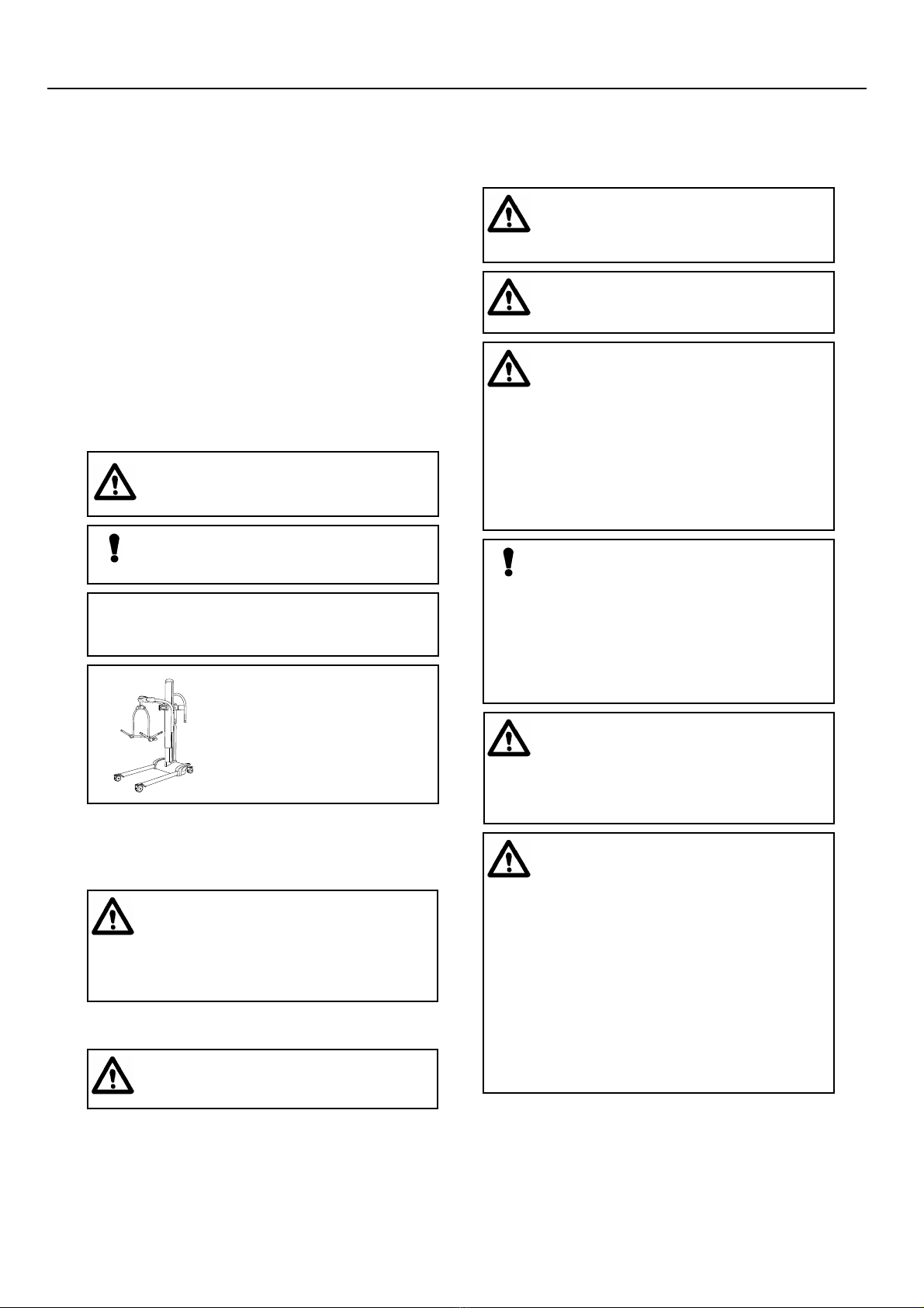
Your Maxi Move is part of a series of quality products
designed especially for hospitals, nursing homes and
other health care uses.
We are dedicated to serving your needs and providing the
best products available along with training that will bring
your staff maximum benefit from every ARJO product.
Please contact us if you have any questions about the
operation or maintenance of your ARJO equipment.
All references to the patient in these instructions refer to
the person being lifted, and references to the attendant
refer to the person who operates the Maxi Move.
Techniques described in these instructions for fitting
slings and lifting patients from a reclining position can
be used for patients regardless of where they may be
lying, on the bed or on the floor.
Similarly, lifting a patient from a chair employs the same
techniques as when lifting a patient from a wheelchair or
from a sitting position on the edge of a bed.
Note: The need for a second attendant to support the
patient must be assessed for each individual case.
These instructions specifically show both the clip
attachment slings being used with the standard Dynamic
Positioning System (DPS) and the loop attachment
slings with the loop spreader bar. The same methods and
techniques described for the standard DPS can also be
applied to the optional powered DPS.
Intended Use
Maxi Move is a mobile passive lift. With a modular
approach, you can create a customized Maxi Move with
the features, accessories and degree of flexibility that
you need for your residents/patients.
Maxi Move is intended to be used in hospitals, nursing
homes or other health care facilities for the different
categories of residents/patients;
where the resident/patient
• sits in a wheelchair
• has no capacity to support him/herself
• cannot stand unsupported and is not able to bear
weight, not even partially
• is dependent on the caregiver in most situations
or, where the resident/patient
• is passive
• might be almost and/or completely bedridden
• is often stiff or has contracted joints
• is totally dependent on the caregiver.
Maxi Move shall always be handled by a trained
caregiver and in accordance with the instructions
outlined in these Operating and Product Care
Instructions.
Maxi Move is intended to be used with ARJO slings.
Only use ARJO-supplied slings and stretchers that are
designed to be used with Maxi Move.
Conditions
• The unit is cared for and serviced in accordance with
recommended, published “Operating and Product
Care Instructions” and the “Preventive Maintenance
Schedule”.
• The unit is maintained to the minimum requirements
as published in the “Preventive Maintenance
Schedule”.
• The servicing and product care, in accordance with
ARJO requirements, must begin on first use of the
unit by the customer.
• The equipment must be used for its intended purpose
only and is operated within the published limitations.
• Only ARJO designated spare parts should be used.
Expected lifetime
The expected lifetime of your ARJO lifter is 10 (ten)
years from the date of manufacture, providing the
following conditions are adhered to:-
The expected lifetime for fabric slings and fabric
stretchers is approximately 2 years from date of
purchase. This life expectancy only applies if the slings
and stretchers have been cleaned, maintained and
inspected in accordance with the “ARJO Sling
Information” documents, the “Operating and Product
Care Instructions” and the “Preventive Maintenance
Schedule”.
The expected lifetime for other consumable products,
such as batteries, fuses, lamps, gel cushions, filters, seal
kits, seat inserts, mattresses, safety belts, padded covers,
straps and cords is dependent upon the care and usage of
the equipment concerned. Consumables must be
maintained in accordance with published “Operating and
Product Care Instructions” and the “Preventive
Maintenance Schedule”.
The date of manufacture is shown in the first 6 digits of
the serial number, e.g. GB0521 123456 (GB = country of
manufacture, 05 = year 2005 and 21 = 21nd week of that
year). The remaining digits, are the machine
identification number.
Policy on number of staff
members required for resident/
patient transfer
ARJO’s passive and active series of lifters are designed
for safe usage with one caregiver. There are
circumstances, such as combativness, obesity,
contractures etc. of the individual that may dictate the
need for a two person transfer. It is the responsibility of
each facility and a professional medical person to make
a determination if a one or two person transfer is more
appropriate, based on task, resident load, environment,
capability, and skill level of the staff member.
Foreword

5
Before using your Maxi Move, familiarise yourself with
the various parts and controls as illustrated in Fig. 1, and
other illustrations, then please read this manual
thoroughly in its entirety before using your Maxi Move.
Information in the manual is crucial to the proper
operation and maintenance of the equipment, and will
help protect your product and ensure that the equipment
performs to your satisfaction. Some of the information in
this booklet is important for your safety and must be read
and understood to help prevent possible injury. If there is
anything in the manual that is confusing or difficult to
understand, please call ARJO Ltd or their appointed
distributor (the telephone number appears on the last
page of this manual.
Symbols used adjacent to the text in these
instructions:-
This product has been designed and manufactured to
provide you with trouble free use, however, this product
does contain components that with regular use are
subject to wear.
See also “Care of your Maxi Move” section.
This product is intended to be operated entirely by an
attendant. No functions regarding the control of this
product should be performed by the patient. A second
attendant may be required with certain patients.
Warning: Means:- failure to understand
and obey this warning may result in injury to
you or to others.
Caution: Means:- failure to follow these
instructions may cause damage to all or parts
of the system or equipment.
• Note: Means:- this is important
information for the correct use of this system
or equipment.
Left
Right
The directions right or left
on the Maxi Move are giv-
en as shown in the illustra-
tion.
Warning: SOME OF THESE PARTS ARE
SAFETY CRITICAL TO THE OPERATION
OF THE LIFTER AND WILL NEED
EXAMINING AND SERVICING ON A
REGULAR BASIS AND MUST BE
REPLACED WHEN NECESSARY.
Warning: Use only ARJO slings and
stretchers that have been specifically designed
for the Maxi Move.
Warning: Before lifting a patient, a clinical
assessment of the patients’ condition and
suitability to be lifted should be carried out by
a qualified person.
Warning: Patients with spasms can be
lifted, but special attention should be paid to
supporting the patient’s legs.
Warning: Do not overload the Maxi Move
beyond the approved lifting capacity of the
lowest rated attachment/accessory.
The Maxi Move may be used on gentle slopes
with caution.
Care should be taken when manually lifting
alternative/optional components e.g. stretcher
frames, spreader bars etc., to avoid injury
Do not attempt to manually lift the complete
lifter.
Caution: Although manufactured to a
high standard the Maxi Move and accessories
should not be left for extended periods in
humid or wet areas.
Do not under any circumstances spray the
Maxi Move or accessories (excluding slings or
ARJO approved wet environment equipment)
with water e.g. under the shower.
Warning: It is advisable to familiarise
yourself and understand the operation of the
various controls and features of the Maxi
Move and ensure that any action or check
specified is carried out before commencing to
lift a patient.
Warning: The ARJO Maxi Move has been
designed as a mobile lifter for raising and
transporting patients in hospitals and care
facility environments, and should only be used
for this purpose.
The ARJO Maxi Move can be supplied with a
variety of optional attachments, which may
not be described in these instructions. If your
Maxi Move has been fitted with an alternative/
optional sub assembly e.g: stretcher etc.: then
always refer to the separate relevant operating
instructions supplement, as well as these
instructions, before attempting to operate the
lifter.
Safety Instructions

6
Fig. 1
P1389ab, P1391c, P1198a, P1391c, P1395e, P1396c, mP1142c
8
22
23
24
21
25
26
Product Description/Function

7
Parts referred to in this manual
Fig. 1 Key
1. Mast
2. Adjustable chassis legs
3. Braked castors
4. Lifter manoeuvring handle
5. Jib
6. Mast top cover
7. DPS spreader bar
8. Loop flat/walking jacket spreader bar
9. Patient positioning handle
10. Lifter battery pack
11. Battery release button
12. Patient scale (if fitted)
13. Control handset
14. Dual control panel
15. Emergency stop button
16. Reset button
17. System failure lower override
18. ---
19. Battery discharge indicator
20. Minute meter
21. Folding stretcher frame (if supplied)
22. Soft stretcher (if supplied)
23. Strap stretcher (if supplied)
24. Scoop stretcher (if supplied)
25. Jib with powered patient positioning spreader bar (if
supplied)
26. Medium loop spreader bar (if supplied)
Product Description/Function
6
10
3
2
12
7
9
5
1
14
13
15
16
20
19
11
10
17
4

8
Slings
A label is fitted to the hanger frame for quick colour to
size reference (see “Labels” section).
A range of special purpose slings are available as
accessories, for these or for special size slings, contact
your ARJO representative.
• Note: The standard range of Maxi
Move slings will support 228kg (500lbs), the
peadiatric range will support 125kg (275lbs).
All slings are coded for size by having
different coloured edge binding as follows:
Peadiatric rated:
Teal -Extra Extra Small - XXS
Brown - Extra small - XS
Red - Small - S
Standard range:
Yellow - Medium - M
Green - Large - L
Purple - Large Large - LL
Blue - Extra Large - XL
Terracotta - Extra Extra Large - XXL
Warning: Only use ARJO supplied slings
and stretchers that are designed to be used
with Maxi Move. The sling profiles illustrated
(see fig. 2) will help to identify the various
ARJO slings and fabric stretchers available.
If ARJO Flites (disposable slings) are to be
used with the Maxi Move, then always refer to
the separate operating instructions for ARJO
Flites, (literature reference part No.
MAX01720), as well as these instructions
before using.
Warning: ARJO slings with head support
have two pockets at the head section which
should contain plastic reinforcement pieces
during use. Always ensure these reinforcement
pieces have been inserted into the sling
pockets before using the sling.
Product Description/Function

9
Four point unpadded
sling
Four point Padded sling Four point mesh sling
Four point amputee sling
General purpose
sling with head
support
Four point toiletting
sling (With headrest)
Toilet sling with
head support
Soft stretcher
Fig. 2
P1390, P1143 a,b, P953 a, b, c, d, e
Product Description/Function
ARJO standard sling profiles that can be used with the Maxi Move

10
Controls and features
The Maxi Move is fitted with a power saving feature
which places the machine in ‘Sleep Mode’ when not
used for a short time, to re-activate the machine press the
up or down button.
Control Handset:-
(see fig 3) Raising and lowering the
jib and opening and closing the chassis legs, is achieved
by pressing the appropriate button on the control
handset. Note: icons with direction arrows are printed on
each button for quick reference.
If pressure is released during any function powered
motion will cease immediately. Do not drop the handset
into water, e.g.: bath etc., although if this does happen
inadvertently no harm will come to patient or attendant.
When not in use, the handset can be conveniently kept
ready for use by hooking it over the handle support at the
rear of the mast.
Dual Control Panel:-
(see fig 4) An additional feature
available on the Maxi Move, is a mast mounted dual
switch panel which operates in parallel with the control
handset enabling powered operations to be controlled
from the lifter mast as well as remotely, using the
handset. As with the handset, icons with direction arrows
are printed on each button for quick reference.
Emergency Stop Button (Red):-
(See fig 5) If, in an
emergency, you have to immediately stop any powered
movement, (other than by releasing pressure on the
control handset button or dual switch panel button),
press the “emergency stop button”, situated on the rear
of the mast.
Once the emergency stop button has been operated, the
green reset button will have to be re-engaged by pressing
it in, before any powered movement can be utilised.
Reset button (green):-
(See fig 5) Adjacent to the
emergency stop button. It is used to reset the ‘power on’
condition, once the emergency stop button has been
operated, also used to reset if the automatic overload fuse
has operated, indicated by the reset button projecting
outwards slightly. If the fuse has operated and once reset,
operates again, withdraw the lifter from use and contact
ARJO Service department or their appointed distributor.
• Note: There will be a 3 seconds delay
before the machine restarts from ‘Sleep
Mode’.
P1396amaxB
Fig. 3
“Raise”
Button
“Lower”
Button
Chassis
leg open
Button
Chassis leg
close
button
Recline
Sit up
Fig. 4
p1396max
“Raise”
Button
“Lower”
Button
Chassis leg
close Button
Chassis leg
open Button
Recline
Sit up
Fig. 5
p1389max
System
Failure
Lower
Override
Hour
meter
Emergency
Stop
Battery
discharge
indicator
Reset
Product Description/Function

11
System Failure Lower Override:-
(See fig 5) This can
be used in the event of main control failure. In the
unlikely event that the control handset or dual switch
panel fails to operate the lifter, with a patient still
supported by the sling or stretcher, provision for
lowering has been made, using the “System Failure
Lower Override switch”, situated on the right hand side
of the controls console, a green and white identification
label is positioned near the switch, for quick and easy
recognition. If pressure is released from the switch
during use, lowering will stop.
System Failure Wind Down Facility:- (see Figs. 6 & 7) If
the electrical power fails completely due to battery
power loss or other electrical malfunction, the jib can be
lowered, by firstly removing the battery pack, then using
a coin or screwdriver slacken and remove the screw that
retains the mast top cover. Slightly lift the rear side of the
top cover approximately 5 mm (3/16 in), slide the cover
forwards then lift it off the mast. Identify and remove the
hexagon wrench located inside the mast. Using the
wrench slacken the shaft lockscrew located at the top
front of the mast (see fig. 7c), turn it 3 full turns anti-
clockwise. Identify the hexagonal hole in the shaft centre
inside the mast (see fig. 7d) and using the wrench turn
the shaft clockwise to lower the patient.
Hold the hexagon wrench securely into the shaft and do
not release hand contact with the wrench to ensure
control is maintained during the lowering procedure.
Once the patient has been lowered and removed from the
lifter ensure the components are re-assembled by
reversing the above procedure.
If the system failure lower override switch or wind down
facility has to be operated the lifter must then be
withdrawn from use immediately and the ARJO Service
Department or their appointed distributor contacted.
Automatic cut out:-
(not an operator control but a
function built into the lifter electronics)
If the lifter is inadvertently overloaded (trying to lift a
patient heavier than permitted), an automatic ‘cut out’
operates to prevent the lifter lifting a load in excess of
one and a half times the maximum rated load; this will
stop the lift motion automatically.
If this occurs, when pressure is released from the lift
button on the handset or dual control the electronics will,
after a short delay, reset and enable the patient to be
lowered only by pressing either lower button. Remove
the patient from the lifter.
Warning: The Lower Override switch will
only operate while the green reset button is in.
Only use this switch in an emergency, do not
use it for normal function lowering.
Fig. 6
P1398a,b
AB
Top
Cover
Wrench
Screwdriver/Coin
• Note: One full clockwise rotation of
the shaft lowers the mast jib by 10mm
(3/8 in).
Fig. 7
P1398c,d
CD
Shaft
lockscrew
Shaft
Warning: If the mast is in a high position
and the wind down facility has to be utilized
always ensure that suitable and safe measures
are taken to gain access to the top cover.
• Note: To enable the shaft lockscrew to
be tightened three full turns the shaft may
have to be rotated slightly to make alignment
possible, this is aided by identifying the
alignment mark on the top of the shaft and
then rotating the shaft until the mark aligns
with the axis of the lockscrew.
Product Description/Function

12
Automatic stop function:-
(not an operator control but
a function built into the lifter electronics).Great care
should be taken not to lower the spreader bar, or stretcher
onto the patient or any other obstruction, but if this
should happen inadvertently the motor will stop and
downward movement will be held by the obstruction. If
this occurs release pressure from the ‘lower’ button
immediately, operate the ‘raise’ button until clear, then
remove the obstruction.
Battery Indicators:-
There are two types of battery indicator; (See fig 5)
A Single red lamp, which will flash when the battery
requires recharging, and a Battery Discharge Indicator
;
this is a small LED display which shows the charge
condition of the lifter battery. (See also ‘Battery
Charging Section’ for complete description).
Minute meter:-
(See fig 5) Is a small LED display which
shows the total duration of powered operation (in hours).
This is primarily intended as an aid to service engineers
and to help the attendant calculate servicing intervals.
The display will illuminate for approx. 5 seconds when
the lifter is first powered on, and when returning from
‘sleep mode’.
Adjustable width chassis legs:-
(See fig 8) By
operating the appropriate button on either the control
handset or dual control panel on the lifter the chassis legs
can be opened to any variable width. When pressure is
released from the button, movement will stop and the
chassis legs will remain securely in position. Always
transport the chassis legs in the narrow (closed) position.
Chassis castor Brakes:-
(See fig 9) The chassis rear
castors have brakes which can be foot operated if
required to keep the Maxi Move in position.
Jib and spreader bars/stretcher frame:-
(see fig 1) If your Maxi Move has not been supplied with
a ‘dedicated’ or permanently attached, spreader bar ,
then it will be supplied with the ‘Lock and Load’ system
jib. This jib is fitted with a carrier, able to accommodate
any of the Maxi Move jib attachments, eg. Loop/DPS
spreader bars, stretcher frame etc. (see “Using your Maxi
Move” section for full instructions on fitting or changing
attachments).
Fig. 8
p1392max
Fig. 9
mP1332e,f
Product Description/Function

13
Before approaching the patient
Ensure the battery pack supplied is fully charged before
use (for charging, see instructions in “Lifter Battery
Charging” section). When the battery pack is fully
charged remove it from the charger unit and insert it into
the battery position of the Maxi Move situated at the rear
of the mast (see Fig. 1) by firstly, locating the recess
across the bottom of the battery with the protrusion at the
bottom of the battery position, then pivot the battery into
position until the retaining catch operates. Electrical
connection will be made automatically.
Ensure the green reset button (situated on the control
console below the dual control panel) is pressed in (see
fig. 5)
Ensure a selection of sling types and sizes are easily
available for all types of lift likely to be encountered
when using the ARJO Maxi Move.
The attendant should always tell the patient what they are
going to do, and have the correct size sling ready. Where
possible, always approach the patient from the front.
If required, the chassis legs may be opened to go around
a chair or wheelchair.
Powered opening ‘V’ chassis
Select the appropriate button on the control handset or
dual switch panel and keep it depressed until the required
width is achieved. To close, press the appropriate button,
movement will stop if pressure is released, whether
opening or closing.
Warning: To ensure maximum patient
comfort, do not allow the patient to hold onto
the spreader bar.
Warning: When opening or closing the
legs on a powered chassis, care must be taken
not to allow anyone to stand in the way of the
moving chassis legs.
Transport the Maxi Move with the chassis legs
in parallel (closed) position only.
Using your Maxi Move

14
Using Maxi Move ‘Lock and Load’
system
(see figs. 10 & 11)
If your Maxi Move has not been supplied with a
‘dedicated’ or permanently attached, spreader bar, then it
will be supplied with the ‘Lock and Load’ System jib.
You may need to fit or change the attachment, (i.e.:
spreader bar or stretcher fame) proceed as follows:-
To remove an existing attachment, hold the unit carefully
and to release, depress the retaining catch on the
attachment yoke (see fig. 10A). Then lift the yoke
upwards and away from the carrier (see fig. 10B and
10C), store carefully for future use. Select the
attachment required then carefully lift the unit up and
allow the recess in the yoke to fit around the carrier shaft
(see fig. 11A). Ensure the yoke drops down over the
carrier and the retaining catch engages.
p1391max, p1439max2, p1439max3
Attachment
yoke
Carrier
Retaining
catch
A
B
C
Fig. 10
Warning: Check to see that the yoke is
locked in place by trying to lift the yoke
without pushing in the retaining catch.
Check that the markings on the hangerbar is
aligned with the corresponding marking on
the carrier (see fig. 11B) which indicates a
proper attachment of the hangerbar to the
carrier.
• Note: The yoke should always be
rotated to the correct position (see Fig. 11A)
before attempting to install an attachment.
P1439max4
A
B
Fig. 11
Warning: Care must be taken when the
weight of the unit comes away from the jib.
For larger attachments or if in any doubt about
being able to lift and hold the attachment
securely use more than one person for the
operation, or support the attachment on a bed
or chair.
Using your Maxi Move

15
Lifting with the DPS spreader bar
To lift from a chair
Place the sling around the patient so that the base of his/
her spine is covered, and the head support area is behind
the head. Pull each leg piece under the thigh so that it
emerges on the inside of the thigh. (See fig. 12).
Ensure the positioning handle on the spreader bar is
facing away from the patient, and that the wide part of
the spreader bar is at, or just below shoulder level. (See
fig. 13).
Ensure that the Maxi Move is close enough to be able to
attach the shoulder clips of the sling to the spreader bar.
To accomplish this you may have to put the patients feet
on, or over the chassis.
Once the Maxi Move is in position, attach the shoulder
strap attachment clips to the pegs on the spreader bar.
(See fig. 14).
Warning: Always ensure that the spreader
bar is securely connected before commencing
any lifting procedure by checking the
alignment of the markings on the spreader bar
and the jib/carrier according to fig. 11B.
(‘Lock and Load’ system jib only)
P1146a,b
Fig 12
Fig 13
p1392maxc
Warning: When fitting and lifting using
the sling with the DPS spreader bar, ensure the
patients hands and arms are at all times kept
inside the sling. Do not allow the patient to
‘hold on’ to the hanger frame.
• Note: The chassis rear castors have
brakes which can be foot operated when
required (see fig.9). Do not apply the castor
brakes at this stage, as the position of the
patient will adjust to his/her own centre of
gravity when lifted.
p1392maxd, p1002
Fig 14
Warning: Apply the castor brakes to keep
the Maxi Move in position on a sloping
surface.
Using your Maxi Move

16
Press down on the positioning handle of the spreader bar
and attach the leg strap attachment clips. (See fig. 15).
If necessary, lower the spreader bar using the handset
control, being careful not to lower it onto the patient,
although if this should happen inadvertently, there is a
built in cut-out device which will prevent any further
downwards movement. Do not continue to press the
handset lowering button.
Raise the patient by operating the handset control, move
the lifter away from the chair then carefully lift the
positioning handle until the patient is reclined in the
sling - the head support will now come into use. (See fig.
16). This is the most comfortable position for
transportation, as it reduces pressure on the thighs. The
angle of recline can be adjusted for increased comfort if
the patient is restless.
Before transportation, turn the patient to face the
attendant at approximately normal chair height. (See fig.
17). This gives confidence and dignity and also improves
the Maxi Move stability.
Remember to release the brakes, if they have been
applied, before attempting to transport the patient.
When lowering the patient back into a chair - or when
transferring from bed to chair - push down on the
positioning handle to put the patient into a good sitting
position. This avoids further lifting effort. Take care not
to push down too quickly, as this may jerk the patient’s
head forward.
P1392maxE
Fig 15
• Note: If the handset button is released
during lifting or lowering, powered motion
will stop immediately.
Warning: IMPORTANT: Always check
that the sling attachment clips are fully in
position before and during the
commencement of the lifting cycle, and in
tension as the patient’s weight is gradually
taken up.
P1393max
Fig 16
P1393maxd
Fig 17
Warning: When lowering the lifter ensure
that the patient’s or attendant’s legs and feet
are well clear of the moving mast.
Using your Maxi Move

17
To lift from a bed
Before lifting a person from a bed, ensure there is
sufficient clearance underneath to accommodate the
Maxi Move chassis legs.
Position the patient onto the sling by rolling the patient
towards you then folding the sling in half and placing it
behind the patient’s back (see fig. 18). Position the sling
carefully so that when rolled back the patient will lie
centrally on the sling (see fig. 19) and check that the head
support area of the sling covers the patient’s neck.
Alternatively, the patient can be brought into a sitting
posture then position the sling as detailed in the section
“To Lift From A Chair”.
Approach the bed with the open side of the spreader bar
towards the patient’s head. (See fig. 20).
Using the adjustable width chassis, it is possible to make
adjustments to chassis leg widths to assist
manoeuvrability around obstructions, for example, bed
legs.
Position the Maxi Move so that the spreader bar is just
above, and centrally situated over the patient.
Using the positioning handle, tilt the spreader bar until
the shoulder attachment points can be connected to the
sling shoulder strap attachment clips. (See fig. 21).
Press down on the positioning handle until connection of
the sling leg pieces is possible. (See fig. 22) The leg
pieces must be brought under the thighs to connect up,
this may involve lifting one leg at a time to connect up.
You may need to lower the spreader bar a little more,
using the handset control.
P1133maxb
Fig 18
P1022a
Fig 19
• Note: When rolling the patient back
onto the sling, roll the patient slightly in the
opposite direction so that the folded part of
the sling can be brought out.
P1393maxe
Fig 20
Warning: Care must be taken not to lower
the spreader bar onto the patient.
P1395maxa, P1002 a,b,c
Fig 21
Using your Maxi Move

18
When lifting from the bed, some attendants prefer to
connect the leg pieces first. This particularly applies to
patients with large thighs. In this case, raise the hip and
knee into maximum flexion, and attach the leg strap
attachment clips, then tilt the spreader bar towards the
shoulders for connection.
Lift the patient using the handset control, and adjust to a
comfortable position for transfer. (See fig. 23). The
specially designed sling together with its’ integral head
support, enables one person to carry out the complete
lifting function without additional help.
If returning the patient to a bed, move into the desired
position above the bed adjusting the sling position as
necessary, and then lower using the handset control.
Move the Maxi Move away before removing the sling
from under the patient. If transferring the patient to a
chair refer to the section “To Lift from a Chair”.
To raise from the floor
Put the sling around the patient as before, by using the
rolling or sitting up method.
Depending on circumstances, space and/or position of
patient etc. approach the patient with the open part of the
chassis. Open the chassis legs if necessary, and lift the
patient’s legs over the chassis as shown in figure 24.
The patient’s head and shoulders could be raised on
pillows for comfort, if required, but this is not essential
when connecting up the sling to the spreader bar.
With the open part of the spreader bar pointing down
towards the shoulders, attach the shoulder strap
attachment clips, as shown in figure 25 and inset.
P1395maxb
Fig 22
Warning: IMPORTANT: Always check
that the sling attachment clips are fully in
position before and during the
commencement of the lifting cycle, and in
tension as the patient’s weight is gradually
taken up.
P1395maxd
Fig 23
Warning: When lowering the lifter ensure
that the patient’s or attendant’s legs and feet
are well clear of the moving mast.
Only when the patient’s body weight is fully
supported by the bed may the sling leg
connection clips be detached, followed by the
shoulder connections.
Caution: Ensure that the sling is not put
around or caught under the legs of the Maxi
Move. This might damage the spreader bar
during the lifting.
P1394a
Fig 24
Warning: Whilst the patient is positioned
over the legs as shown in fig 24, DO NOT
operate the leg actuator.
Using your Maxi Move

19
Once connected, raise the hip and knee into maximum
flexion, and push down on the positioning handle in
order to connect the leg strap attachment clips as shown
in figure 26. This will have the effect of raising the
patient’s head and shoulders slightly.
When lifting from the floor, some attendants prefer to
connect the leg pieces first. This in particular applies to
the very large patient with large thighs. In this case, raise
the hip and knee into maximum flexion, and attach the
leg straps first, then tilt the spreader bar towards the
shoulders to enable the shoulder straps to be connected.
When all the straps have been properly connected, raise
the patient from the floor in a semi-recumbent position.
Supporting the head can be comfortable and reassuring
for the patient. Once raised from the floor, ensure the
patient’s legs are clear of the chassis before continuing to
lift. (See fig. 27). The leg sections of the sling will tend
to be fairly high in the crotch, so straighten them out for
added comfort. The patient may be positioned in a chair,
or placed onto a bed. If the patient is prone to extensor
spasm, he/she may be lifted by the Maxi Move, but
special attention should be paid to supporting the legs
during the early part of the lift.
When lifting patient’s with leg amputations, use the
double amputee sling (available as an accessory from
ARJO Ltd). This sling is specially designed to
accommodate the differing patient centre of gravity.
P1394maxb, P1002 a,b,c
Fig 25
P1394maxc
Fig 26
Warning: IMPORTANT: Always check
that the sling attachment clips are fully in
position before and during the
commencement of the lifting cycle, and in
tension as the patient’s weight is gradually
taken up.
P1394maxd
Fig 27
Warning: When lowering the lifter ensure
that the patient’s or attendant’s legs and feet
are well clear of the moving mast.
Transportation of a patient should always be
done with the chassis legs parallel (closed)
manoeuvrability will be easier, especially
through doorways, with the chassis legs
closed. The patient should be positioned
facing the attendant. (See fig. 17).
Using your Maxi Move

20
Lifting with Powered DPS
spreader bar (if fitted)
If your lifter has been supplied fitted with a powered DPS
spreader bar, the use of this type of spreader bar
including sling positioning with patient, sling
connection to the spreader bar, and patient handling, is
the same as the non-powered DPS spreader bar described
previously in these instructions.
The fundamental difference being, the powered DPS
spreader bar has the added advantage of enabling the
patient positioning manoeuvre to be performed with
minimal physical effort by the attendant.
Rotation of the powered spreader bar is manual and is the
same as the manual patient positioning spreader bar.
The powered DPS is waterproof and is classified by
ARJO as a wet environment unit and has a blue and white
circular label to qualify this, attached. (See “Labels”
Section). This label signifies that the lower end of the
unit may be immersed in bath water, or used for
showering.
To operate the powered patient positioning function,
ensure the isolator/cut off switch is in the on position
When ready to perform the patient positioning function
(as described previously) operate the powered DPS
control button (see fig. 29) to achieve spreader bar
movement in the required direction.
Powered movement will continue until pressure is
released from the control switch.
The spreader bar will remain firmly in position, once
powered movement has ceased.
Warning: Always ensure that the spreader
bar is securely connected before commencing
any lifting procedure by checking the
alignment of the markings on the spreader bar
and the jib/carrier according to fig. 11B.
(‘Lock and Load’ system jib only)
P1397maxa
Rotational
positioning
handle
Sling
attachment
lugs
Fig 28
Warning: Before using your lifter when
fitted with the powered DPS spreader bar,
familiarise yourself with the various parts as
illustrated in figure 28. then read and
thoroughly understand the following
operating instructions.
The powered DPS spreader bar must be used
in accordance with the following instructions
and in conjunction with the operating
instructions previously described for the
manually operated (non-powered) four point
spreader bar.
The lifting capacity of the lifter when fitted
with the powered DPS spreader bar remains
the same as the non-powered patient
positioning spreader bar version.
P1396amaxB
“Raise”
Button
“Lower”
Button
Chassis
leg open
Button
Chassis leg
close
button
Recline
Sit up
Fig 29
Warning: To stop any powered movement,
release pressure from the control switch or
press the emergency stop button.
Warning: Before and during operating the
powered DPS spreader bar, ensure all
obstructions are well clear of the spreader bar,
support frame and jib.
Using your Maxi Move
Other manuals for MAXI MOVE
5
Table of contents
Other Arjo Mobility Aid manuals

Arjo
Arjo MAXI MOVE Installation guide

Arjo
Arjo MAA2070M User manual

Arjo
Arjo Voyager User manual

Arjo
Arjo MLA4060 User manual

Arjo
Arjo Walker Hydraulic User manual

Arjo
Arjo Maxi Sky 440 Installation guide

Arjo
Arjo Maxi Twin User manual

Arjo
Arjo Walking Jacket User manual

Arjo
Arjo MAV1816 User manual

Arjo
Arjo Sara 3000 User manual