Arjo MAXI MOVE Installation guide

001.25060.EN_rev2
May 2008
MAXI MOVE™
Operating and Product Care Instructions

© ARJO International 2008
ARJO products are patented or patent pending. Patent
information is available by contacting ARJO
International AB.
Our policy is one of continuous development, and we
therefore reserve the right to make technical alterations
without notice. The content of this publication may not
be copied either whole or in part without the consent of
ARJO International AB.

3
Contents .............................................................................................. 3
Definitions Used in this Manual: ............................................... 5
Manufacturer Information .......................................................... 5
Authorized European Representative ......................................... 5
Intended Use ............................................................................... 5
Conditions .................................................................................. 5
General Information .......................................................................... 5
Operational Life ......................................................................... 6
Number of Staff Members and Transfers ................................... 6
Safety Instructions ............................................................................. 7
Symbols Used ............................................................................. 7
Product Description/Functions......................................................... 9
Parts Referred to in this Manual ................................................. 9
Slings ........................................................................................ 11
Controls and Features ............................................................... 13
Control Handset .................................................................. 13
Control Panel ...................................................................... 13
Stop Button (red) ................................................................ 13
Power Button (green) ......................................................... 14
System Failure Wind-Down Facility................................... 14
Automatic Cut-Out ............................................................. 14
Anti-Crush System ............................................................. 14
Battery Indicator ................................................................. 14
Sleep Mode ......................................................................... 15
Usage Counter .................................................................... 15
Adjustable Width Chassis Legs .......................................... 15
Chassis Castor Brakes ........................................................ 15
Jib and Spreader Bars/Stretcher Frame .............................. 15
Using Your Maxi Move ................................................................... 16
Before Approaching the Patient ............................................... 16
Powered Opening “V” Chassis ................................................ 16
Maxi Move ‘Lock and Load’ System ...................................... 16
Using the DPS Spreader Bar .................................................... 17
To Lift from a Chair ........................................................... 17
To Lift from the Bed .......................................................... 18
To Lift from the Floor ........................................................ 20
Powered DPS Spreader Bar ..................................................... 21
Care of Your Powered DPS Spreader Bar .......................... 22
Using the Loop Spreader Bar ................................................... 22
To Lift from a Chair ........................................................... 22
To Lift from the Bed .......................................................... 23
To lift from the Floor .......................................................... 24
Using the Stretcher Frame ........................................................ 24
Using the Soft Stretcher ........................................................... 24
Using the Strap Stretcher ......................................................... 26
Contents

4
Contents
Scale .................................................................................................. 29
Patient Scale Information ......................................................... 29
Descriptive Marking/Seals E.C. Units only ............................. 29
Reinspection ............................................................................. 30
Display Symbols/Functions ..................................................... 30
Overload Warning Symbol ...................................................... 30
Method A - Weighing Before the Patient is Suspended
in the Sling ............................................................................... 30
Method B - Weighing with the Patient Already
Suspended in the Sling ............................................................. 31
Units of Measure ...................................................................... 33
Scale - Handset Instruction Mini-Guide ................................... 34
Scale - Handset Instruction Mini-Guide .................................. 35
Battery Charging ............................................................................. 36
Battery Pack ............................................................................. 36
Removing the Battery Pack ...................................................... 36
Charging your Battery .............................................................. 36
Battery and Battery Charger Safety Practices .......................... 36
Care of Your Maxi Move ................................................................ 37
Sling Cleaning and Care: ......................................................... 37
Lift Cleaning and Care ............................................................. 37
Mandatory Daily Checks .......................................................... 37
Periodic Testing ....................................................................... 37
Servicing Advice ...................................................................... 38
Troubleshooting ............................................................................... 39
Labels ................................................................................................ 40
Technical Specifications .................................................................. 41
Lift Dimensions ........................................................................ 42
Appendix - Scale Gravity Code Configurations ........................... 43
Viewing the Gravity Code Configuration ................................ 43
European Gravity Zones Map .................................................. 44
Gravity Adjustment Table ........................................................ 46

5
Thank you for purchasing ARJO equipment.
Your Maxi Move is part of a series of quality products
designed especially for hospitals, nursing homes and
other health care uses.
We are dedicated to serving your needs and providing
the best products available along with training that will
bring your staff maximum benefit from every ARJO
product.
Please contact us if you have any questions about the
operation or maintenance of your ARJO equipment.
All references to the patient in these instructions refer to
the person being lifted, and references to the attendant
refer to the person who operates the Maxi Move.
Techniques described in these instructions for fitting
slings and lifting patients from a reclining position can
be used for patients regardless of where they may be
lying; on the bed or on the floor.
Similarly, lifting a patient from a chair employs the same
techniques as when lifting a patient from a wheelchair or
from a sitting position on the edge of a bed.
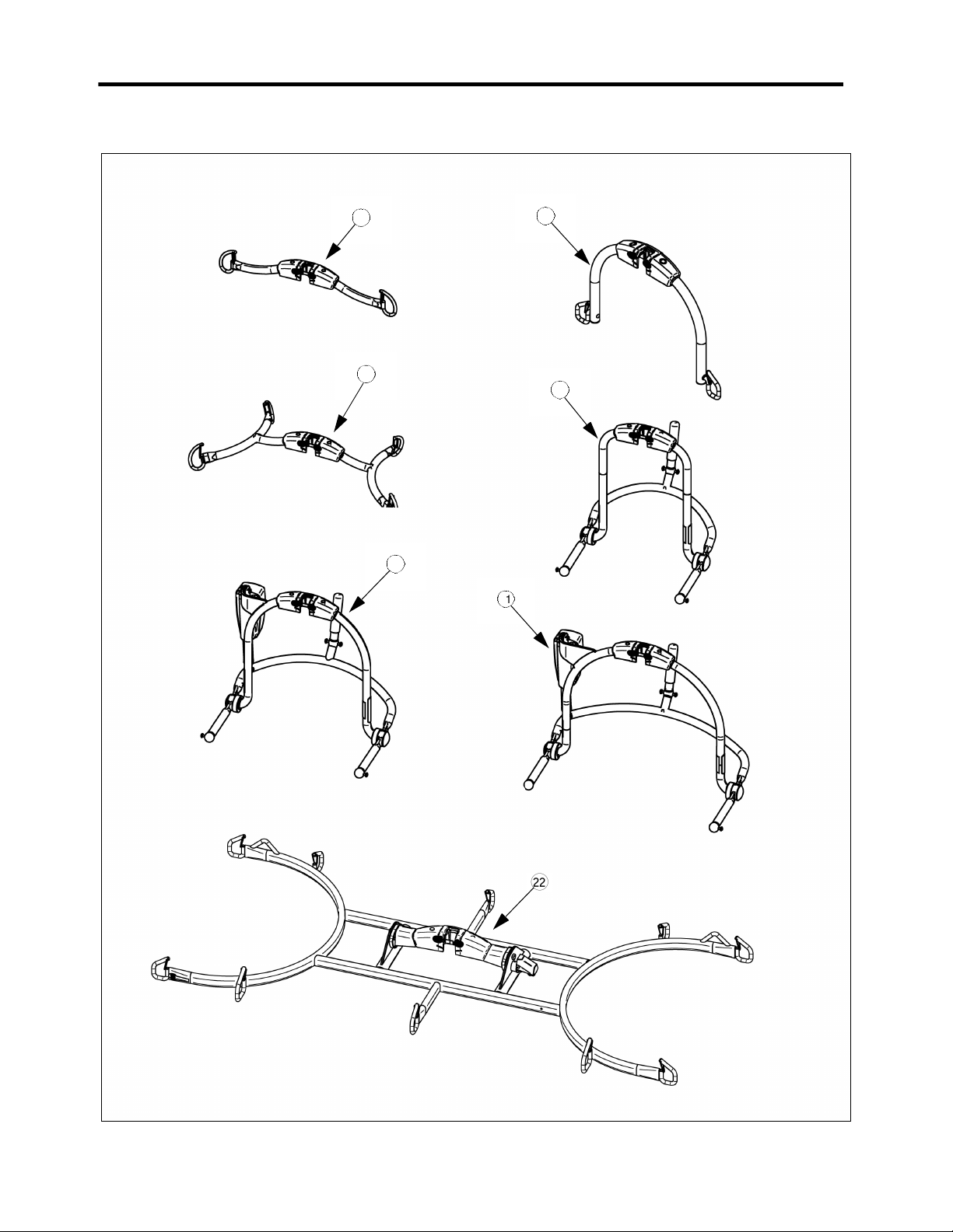
These instructions specifically show both the clip
attachment slings being used with the standard Dynamic
Positioning System (DPS) and the loop attachment
slings for loop spreader bars. The same methods and
techniques described for the standard DPS can also be
applied to the optional, powered DPS.
Definitions Used in this Manual:
Means: Failure to understand and follow these
instructions may result in injury to yourself and others.
Means: Failure to follow these instructions may cause
damage to the product(s).
Means: This is important information regarding the
correct use of the equipment.
Manufacturer Information
This product has been manufactured by:
BHM Medical Inc.
2001 Tanguay Street
Magog (Quebec)
Canada J1X 5Y5
Authori ed European
Representative
Huntleigh Healthcare Ltd.
310-312 Dallow Road
Luton, UK
LU1 1TD
Intended Use
Maxi Move is a mobile, passive lift with removable
spreader bar.
Maxi Move is intended to be used in hospitals, nursing
homes or other health care facilities where the patient:
• sits in a wheelchair
• has no capacity to support himself/herself
• cannot stand unsupported and is not able to bear
weight; not even partially
• is dependent on the caregiver in most situations
Or where the patient:
• is passive
• might be almost or completely bedridden
• is often stiff or has contracted joints
• is totally dependent on the caregiver
Maxi Move must always be handled by a trained
caregiver and in accordance with the instructions
outlined in these Operating and Product Care
Instructions.
Maxi Move is intended to be used with ARJO slings.
Only use slings and stretchers supplied by ARJO that are
designed to be used with your Maxi Move.
Conditions
• The unit is cared for and serviced in accordance with
recommended, published “Operating and Product
Care Instructions” and the “Preventive Maintenance
Schedule”.
• The unit is maintained to the minimum requirements
as published in the “Preventive Maintenance
Schedule”.
• The servicing and product care, in accordance with
ARJO requirements, must begin on first use of the
unit by the customer.
• The equipment must be used for its intended purpose
only and is operated within the published limitations.
Only ARJO designated spare parts should be used.
NOTE: The need for a second attendant to
support the patient must be assessed in each
individual case.
WARNING:
CAUTION:
NOTE:
WARNING: To avoid injuries that can be
attributed to the use of inadequate parts,
ARJO strongly advises and warns that only
ARJO designated parts should be used on
equipment and other appliances supplied by
ARJO. Unauthorized modifications on any
ARJO equipment may affect its safety. ARJO
will not be held responsible for any accidents,
incidents or lack of performance that occur as
a result of any unauthorized modification to its
products.
General Information

6
General Information
Operational Life
The expected operational life of your ARJO lift is ten
years from the date of manufacture, providing the
following conditions are adhered to:
• The expected operational life for fabric slings and
fabric stretchers is approximately two years from
date of purchase.
• This life expectancy only applies if the slings and
stretchers have been cleaned, maintained and
inspected in accordance with the “ARJO Sling
Information” documents, the “Operating and Product
Care Instructions” and the “Preventive Maintenance
Schedule”.
• The expected life for other consumable products,
such as batteries, fuses, lamps, gel cushions, filters,
seal kits, seat inserts, mattresses, safety belts, padded
covers, straps and cords is dependent upon the care
and usage of the equipment concerned.
Consumables must be maintained in accordance with
published “Operating and Product Care Instructions”
and the “Preventive Maintenance Schedule”.
Policy on Number of Staff
Members Required for Patient
Transfer
ARJO’s passive and active series of lifts are designed for
safe usage with one caregiver. There are circumstances,
such as combativness, obesity, contractures etc. of the
individual that may dictate the need for a two-person
transfer. It is the responsibility of each facility or medical
professional to determine if a one or two person transfer
is more appropriate, based on the task, resident load,
environment, capability, and skill level of the staff
members.

7
Symbols Used
Fig. 1
Symbol Key to symbol
This symbol is accompanied by the name and the address of the authorized
representative in the European Community.
This symbol is accompanied by a date (to indicate the date of manufacture) and by
the address of the manufacturer.
This symbol indicates that the products comply with medical device directive
93/42/EEC.
This symbol is accompanied by the manufacturer's catalogue number.
This symbol is accompanied by the manufacturer's serial number.
This symbol indicates “separate collection” for all batteries and accumulators as
per the WEEE Directive.
These symbols refer to the Operating and Product Care Instructions.
This symbol indicates a class II electrical equipment: term referring to electrical
equipment in which protection against electric shock does not rely on basic
insulation only.
This symbol indicates a type B applied part.
This symbol indicates a risk of pinching.
This symbol represents a weight scale.
This symbol indicates that the scale is a non-automatic instrument; medium
accuracy class.
Safety Instructions

8
Safety Instructions
Before using your Maxi Move, familiarize yourself with
the various parts and controls as illustrated in Fig. 3, and
other illustrations. Then, read this manual thoroughly in
its entirety before using your Maxi Move. Information in
the manual is crucial to the proper operation and
maintenance of the equipment, and will help protect
your product and ensure that the equipment performs to
your satisfaction. Some of the information in this
booklet is important for your safety and must be read and
understood to help prevent possible injury. If there is
anything in the manual that you find is confusing or
difficult to understand, please contact your local ARJO
representative (the telephone number appears on the last
page of this manual).
Fig. 2
This product has been designed and manufactured to
provide you with trouble-free use. However, this product
does contain components that are subject to wear with
regular use.
See also “Care of Your Maxi Move” section.
The Maxi Move can be supplied with a variety of
optional attachments, which are not all described in
these instructions. If your Maxi Move has been equipped
with an alternative/optional sub-assembly such as
stretchers, etc., always refer to the separate, relevant
operating instructions supplement, as well as these
instructions, before you operate the lift. Only use ARJO-
supplied slings and stretchers that are designed to be
used with Maxi Move.
This product is intended to be operated entirely by an
attendant. The patient should not perform any function
relating to the control of this product. A second attendant
may be required with certain patients.
References to “left” or
“right” in these
instructions are as
viewed from the
caregiver’s pushing
position, standing at the
rear of the Maxi
Move and facing
forward.
CAUTION: Some of these parts are critical to
ensure the safe operation of the lift. They will
need examining and servicing on a regular
basis and must be replaced as needed.
CAUTION: Use only ARJO slings and
stretchers that have been specifically
designed for the Maxi Move.
WARNING: Before lifting a patient, a clinical
assessment of the patient’s condition and
suitability to be lifted should be carried out by
a qualified professional.
WARNING: Patients with spasms can be lifted,
but great care should be taken to support the
patient’s legs.
WARNING: Do not overload the Maxi Move
beyond the approved lifting capacity of the
lowest rated attachment/accessory. If the
maximum load differs between floor lift,
spreader bar and body support unit (i.e. sling),
then the lowest maximum load shall always be
used.
Take care when manually lifting alternative/
optional components such as stretcher
frames, spreader bars etc., in order to avoid
injury.
Do not attempt to manually lift the complete
lift.
CAUTION: Although manufactured to a high
standard, the Maxi Move and accessories
should not be left in humid or wet areas.
Do not, under any circumstances, spray the
Maxi Move or accessories (excluding slings or
ARJO approved wet environment equipment)
with water such as under the shower.
WARNING: Before lifting a patient it is
advisable to familiarize yourself with and
understand the operation of the various
controls and features of the Maxi Move, and to
carry out any action concerning inspection
procedures.

9
Parts Referred to in this Manual
Fig. 3
1
2
3
6
7
9
8
10
11
5
12
13
14
15
4
1) Mast
2) Mast top cover
3) Maneuvering handle
4) Lift battery pack
5) Braked casters
6) Adjustable chassis legs
7) Medium DPS spreader bar (if included)
8) “Lock and Load” spreader bar carrier system
9) Jib
10) Control panel
11) Control handset
12) Stop button
13) Power button
14) Battery release button
15) Battery charger
16) Two-point loop spreader bar (if included)
17) Combi medium loop spreader bar (if included)
18) Four-point loop spreader bar (if included)
19) Small DPS spreader bar (if included)
20) Medium powered DPS spreader bar (if included)
21) Large powered DPS spreader bar (if included)
22) Stretcher frame (if included)
Product Description/Functions

10
Product Description/Functions
Fig. 4
16
17
18
19
20
20
1

11
Product Description/Functions
Slings
The standard range of Maxi Move slings will support
227 kg (500 lb), the pediatric spreader bar range will
support 125 kg (275 lb). All slings are size-coded with
different colored edge binding or attachment strap
coloring:
Pediatric rated:
• Teal -Extra Extra Small - XXS
• Brown - Extra Small - XS
• Red - Small - S
Standard Range:
• Yellow - Medium - M
• Green -Large - L
• Purple - Large Large - LL
• Blue - Extra Large - XL
• Terracotta - Extra Extra Large - XXL
Always refer to the label on the sling being used to make
sure of its actual safe working load (SWL).
A label is placed on the spreader bar for a quick color-to-
size reference (see the section entitled “Labels”).
A range of special purpose slings is available as
accessories. For these or for special size slings, contact
your ARJO representative.
WARNING: Only use ARJO supplied slings
and stretchers that are designed to be used
with Maxi Move. The sling profiles illustrated
(see Fig. 5) will help to identify the various
ARJO slings and fabric stretchers available.
If ARJO Flites (disposable slings) are to be
used with your Maxi Move, always refer to the
separate operating instructions for ARJO
Flites (literature reference part No.
MAX01720), as well as these instructions,
before using.
WARNING: ARJO slings with head supports
have two pockets located in the head section.
These should contain plastic reinforcement
inserts during use. Always ensure that these
reinforcement inserts have been placed inside
the sling pockets before using the sling.

12
ARJO standard sling profiles that can be used with the Maxi Move
Fig. 5
Soft stretcher
Four-point padded sling Four-point toileting sling Four-point amputee sling
Strap stretcher
Scoop stretcher
Product Description/Functions

13
Product Description/Functions
Controls and Features
Control Handset
(See Fig. 6) To raise and lower the jib, open and close the
chassis legs, or to operate a powered DPS spreader bar,
press the appropriate button on the control handset.
Icons with direction arrows are printed on each button
for quick reference.
Fig. 6
If button is released during any function, powered
motion will cease immediately. When not in use, the
handset can be conveniently stored for later use by
hooking it over the manoeuvring handle at the rear of the
mast.
Control Panel
(See Fig. 7) An additional feature available on the Maxi
Move, is a mast-mounted control panel, which operates
in parallel with the control handset, enabling powered
operations to be controlled from the lift mast as well as
remotely by using the handset. As with the handset,
icons with direction arrows are printed on each button
for quick reference.
Fig. 7
Stop Button (red)
(See Fig. 8) In an emergency, if you have to immediately
stop any powered movement (other than by releasing a
control handset button or control panel button), press the
stop button located on the control panel.
Once the stop button has been used, the green power
button will have to be pressed before the equipment can
be operated again. To do this, simply push in the button.
Fig. 8
Jib “Up”
button
DPS “Sit up”
button
Chassis
“Legs open”
button
Handset
display
Jib “Down”
button
DPS “Recline”
button
Chassis
“Legs Closed”
button
DPS “Recline”
button
Jib “Down”
button
Chassis
“Legs closed”
button
DPS
“Sit up”
button
Jib “Up”
button
Chassis
“Legs
open”
button
Stop button
Power
button

14
Product Description/Functions
Power Button (green)
(See Fig. 8) Located adjacent to the stop button, this
button is used to turn the unit on.
System Failure Wind Down Facility
If electrical power fails completely due to battery power
loss or other electrical malfunction, the jib can be
lowered by first raising the red colored emergency
lowering lever found on the rear section of the mast (See
Fig. 9).
Fig. 9
Next, remove the exposed locking pin from its location
beneath the red colored emergency lowering lever (see
Fig. 10).
Fig. 10
Finally, using the lever as a crank, turn it in a clockwise
rotation (see Fig. 11). One full clockwise rotation of the
shaft lowers the mast jib by 10 mm (3/8 in).
Fig. 11
If the wind down function must be used, immediately
remove the lift from use and contact the ARJO Service
Department or its appointed distributor.
Automatic Cut-Out
This is not an operator control but a function built into
the lift’s electronics.
If the lift is inadvertently overloaded by trying to lift a
load heavier than permitted, an automatic “cut-out”
function operates to prevent the lift from raising a weight
in excess of the safe working load (SWL). This will stop
the lift’s motion automatically.
If this occurs, release the jib “up” button on the handset
or the control panel. The electronics will reset after a
short delay to enable the patient to be lowered only when
either of the “down” buttons is pressed. Make sure that
the Maxi Move operates only within its safe working
load.
Anti-Crush System
This is not an operator control but a function built into
the lift’s electronics.
Great care should be taken not to lower the spreader bar,
or stretcher onto the patient or any other obstruction. If
this should happen, the unit’s “anti-crush” system will
engage, stop the motor and all downward movement will
cease. If this occurs, release the jib “down” button
immediately and press the jib “up” button to raise the jib
until the lift is clear. Then remove the obstruction.
Battery Indicator
The battery indicator for the Maxi Move is a feature
found on the control handset. Please refer to the “Battery
Charging” section for operating procedures.
WARNING: If the mast is in a high position and
the wind down function must be used, ensure
that suitable and safe measures are taken to
gain access to the top cover.

15
Product Description/Functions
Sleep Mode
The Maxi Move is equipped with a power-saving feature
which places the machine in “sleep mode” when not
used for a short time. The unit is put into sleep mode in
two stages:
1) After two minutes of inactivity (where no buttons
are pressed on either the control handset or control
panel), the handset’s display will go into sleep
mode. The display can be taken out of sleep mode
by pressing any button on the handset or the control
panel. There will be a three second delay after
which the unit is fully ready for use.
2) After six minutes of inactivity, the entire unit will
placed into sleep mode and will restart only when a
button is pressed either on the control handset or
control panel. There will be a three second delay
after which the unit is fully ready for use.
Usage Counter
The usage counter is a feature found on the control
handset which shows the accumulated amount of time
(in hours) that the lift’s mast has been raised or lowered.
Initially, the display will show “0.0” at the very top of the
screen (right above the larger digits for the scale),
indicating 0 hours of use. The measurement will increase
in increments of 0.1 whenever an additional six minutes
have been accumulated. Note that the counter is
recording only during the movement of the mast.
Keeping the unit turned on, using the powered DPS or
adjusting the width of the legs will not affect the usage
counter.
The maintenance symbol serves as a reminder of
the annual maintenance requirements for the product. It
will appear on the handset display when the usage
counter reaches 175 hours. This target represents the
average time a lift will be used during one year.
However, based on the use of the unit, the maintenance
symbol can appear sooner or later than a year.
When the maintenance symbol appears, the unit will still
be safe to use, but the annual maintenance should be
performed as soon as it is reasonably possible.
Adjustable Width Chassis Legs
(See Fig. 12) To open the chassis legs, press the “legs
open” button on either the control handset or control
panel. When the button is released, movement will stop
and the chassis legs will remain securely in position.
Always transfer patients with the chassis legs in the
closed position.
Fig. 12
Chassis Castor Brakes
(See Fig. 13) The chassis rear castors have brakes which
can be foot operated to keep the Maxi Move in position.
Fig. 13
Jib and Spreader Bars/Stretcher Frame
(Consult Fig. 3) Your Maxi Move is equipped with a
quick connection device that allows you to use multiple
attachments, such as loop/DPS spreader bars, stretcher
frames, etc. See the section entitled “Using your Maxi
Move” for full instructions on installing or changing
attachments.
Lock brake
Unlock brake

16
Before Approaching the Patient
Ensure that the battery pack supplied is fully charged
before use (for recharging batteries, see the instructions
in the “Battery Charging” section). When the battery
pack is fully charged, remove it from the charger unit
and insert it back into the Maxi Move. First, match the
recess across the bottom of the battery pack with the
protrusion at the bottom of the battery slot, then pivot the
battery into position until the retaining catch engages.
An electrical connection will be made automatically.
Ensure that the green power button (located below the
control panel) is pushed in (see Fig. 8).
Ensure that a selection of sling types and sizes is
available for all transfers likely to be performed using
the Maxi Move.
The attendant should always tell the patient what they
are going to do, and have the correct size sling ready.
Whenever possible, always approach the patient from
the front.
If required, the chassis legs may be opened to go around
a chair or wheelchair.
Powered Opening “V” Chassis
Push the “legs open” button on the control handset or
control panel until the required width for the chassis legs
is reached. To close, press the “legs closed” button.
Movement will stop if the button is released, whether
opening or closing.
When opening or closing the legs on a powered chassis,
care must be taken not to allow anything to stand in the
way of the chassis’ moving legs. For example, pay
special attention when the legs are operated around
chairs or in doorways.
The lift must be moved only when the chassis legs are in
the closed position.
Maxi Move ‘Lock and Load’
System
(Consult Fig. 14)
If you need to install or change the attachment, such as
the spreader bar or stretcher frame, proceed as follows:
To remove the spreader bar, hold it carefully and depress
the retaining catch to release it from the carrier (see A).
Then lift the spreader bar upwards and away from the
carrier (see B and C), and store it carefully for future use.
Finally, select the attachment required and—while
carefully lifting it up—allow the recess in the spreader
bar to fit around the carrier shaft (see D). Ensure the
spreader bar drops down over the carrier and that the
retaining catch engages fully.
Fig. 14
WARNING: To ensure the patient’s maximum
comfort, do not allow the patient to hold on to
the spreader bar.
Locking
clip
Spreader bar
Carrier
A
B
C
D
Using your Maxi Move

17
Using your Maxi Move
Using the DPS Spreader Bar
Ensure the spreader bar is securely connected to the jib
before starting to lift.
To Lift from a Chair
Place the sling around the patient so that the base of his/
her spine is covered and the head support portion of the
sling is behind the head. Pull each leg strap from under
the thigh so that it emerges on the inside of the thigh (see
Fig. 15).
Fig. 15
Ensure the positioning handle on the spreader bar is
facing away from the patient, and that the open part of
the spreader bar is at or just below shoulder level (see
Fig. 16).
Fig. 16
Ensure that the Maxi Move is close enough to be able to
attach the sling’s shoulder clips to the spreader bar. To
accomplish this you may have to put the patient’s feet on,
or over, the chassis.
Once the Maxi Move is in position, attach the shoulder
strap attachment clips to the sling attachment lugs on the
spreader bar (see Fig. 17).
Fig. 17
Press down on the positioning handle on the spreader bar
and attach the leg strap attachment clips (see Fig. 18).
Fig. 18
If necessary, lower the spreader bar using the handset
control, being careful not to lower it onto the patient. If
this should happen inadvertently, there is a built-in cut-
out device which will prevent any further downward
movement. Do not continue to push the handset “jib
down” button.
WARNING: Be prepared to take the full weight
of the spreader bar when removing it from the
jib.
For larger attachments, or if there is any doubt
about being able to lift and hold the
attachment securely, use more than one
person for the procedure, or support the
attachment on a bed or chair.
WARNING: When installing and lifting using
the sling with the DPS spreader bar, ensure
that the patient’s hands and arms are kept
inside the sling at all times. Do not allow the
patient to hold on to the spreader bar.
CAUTION: The chassis rear castors have
brakes which can be foot-operated when
required (see Fig. 13). Do not apply the chassis
brakes at this stage, as the position of the
patient will adjust to the center of gravity of the
lift while the patient is being raised.

18
Using your Maxi Move
If the handset button is released during the lifting or
lowering procedure, powered motion will stop
immediately.
Before transferring, position the patient to face the
attendant at approximately the height of a normal chair.
This provides a measure of confidence and dignity to the
patient.
Remember to release the brakes if they have been
applied, before transferring the patient.
Lift the patient using the handset control, and adjust to a
comfortable position for transfer (see Fig. 19). The
specially designed sling, together with its integral head
support, enables one person to carry out the complete
lifting function without additional help.
Fig. 19
Move the lift away from the chair. The angle of recline
can be adjusted to increase comfort for more restless
patients. The lift can now be directed towards the
following transfer point (see Fig. 20).
Fig. 20
When lowering the patient back down, lower the
positioning handle to put the patient into a sitting
position. This avoids further lifting strain. Take care not
to push down too quickly, as this may jerk the patient’s
head forward.
To Lift from the Bed
Before lifting a person from a bed, ensure there is
sufficient clearance underneath the bed to accommodate
the Maxi Move chassis legs.
Position the patient onto the sling by rolling the patient
towards you, then folding the sling in half and placing it
behind the patient’s back (see Fig. 21).
Fig. 21
Position the sling carefully so that, when rolled back, the
patient will lie on the center of the sling (see Fig. 22).
Check that the head support area of the sling covers the
patient’s neck.
CAUTION: Always check that all the sling
attachment clips are fully in position before
and during the lifting cycle, and in tension as
the patient’s weight is gradually taken up.
WARNING: Do not attempt to maneuver the lift
by pulling or pushing on the mast, the jib, the
spreader bar or the patient as this can cause
the lift to topple over.
WARNING: When lowering the spreader bar,
ensure that the patient’s and attendant’s legs
and feet are well clear of the moving mast.
Only detach the sling leg connection clips
followed by the shoulder connection clips
when the patient’s body weight is fully
supported by the bed.

19
Using your Maxi Move
Fig. 22
When rolling the patient back onto the sling, roll the
patient slightly in the opposite direction so that the
folded part of the sling can be pulled forward.
Alternatively, the patient can be brought into a sitting
posture. Then position the sling as detailed in the section
entitled “To Lift From A Chair”.
Approach the bed with the open side of the spreader bar
towards the patient’s head (see Fig. 23).
Fig. 23
Using the adjustable width chassis, it is possible to make
adjustments to the chassis leg width to assist with
manoeuvrability around obstructions, such as bed legs or
castors.
Now position the Maxi Move so that the spreader bar is
just above and centered over the patient.
Using the positioning handle, tilt the spreader bar until
the shoulder attachment points can be connected to the
sling shoulder strap attachment clips (see Fig. 24).
Fig. 24
Press down on the positioning handle until the sling leg
sections can be connected (see Fig. 25). Connect the leg
sections under the thighs by lifting one leg at a time. You
may need to lower the spreader bar a little, using the
handset control.
Fig. 25
When lifting from the bed, some attendants prefer to
connect the leg straps first. This applies in particular to
patients with large thighs. In that case, raise the hip and
knee into maximum flexion, and attach the leg strap
attachment clips. Then tilt the spreader bar towards the
shoulders to connect the shoulder attachment clips.
Lift the patient using the handset control, and with the
positioning handle, bring the patient into a comfortable
position for transfer (see Fig. 26). The specially designed
sling, together with its integral head support, enables one
person to carry out the complete lifting function without
additional help.
WARNING: Take care not to lower the spreader
bar onto the patient.
CAUTION: Always check that all the sling
attachment clips are fully in position before
and during the lifting cycle, and in tension as
the patient’s weight is gradually taken up.

20
Using your Maxi Move
Fig. 26
If returning the patient to a bed, move into the desired
position above the bed, adjusting the spreader bar
position as necessary. Then lower the patient using the
handset control.
Pull the Maxi Move away before removing the sling
from under the patient. If transferring the patient to a
chair, refer to the section entitled “To Lift from a Chair”.
To Lift from the Floor
Put the sling around the patient, by rolling or sitting the
patient up. Open the chassis legs first, then approach and
lift the patient’s legs over the chassis as shown in Fig. 27.
Fig. 27
When connecting the sling to the spreader bar, the
patient’s head and shoulders could be raised with pillows
for additional comfort.
With the open part of the spreader bar pointing down
towards the shoulders, attach the shoulder strap
attachment clips, as shown in Fig. 28 and inset.
Fig. 28
Once connected, raise the hip and knee into maximum
flexion, and push down on the positioning handle to be
able to connect the leg strap attachment clips as shown
in Fig. 29. This will have the effect of raising the
patient’s head and shoulders slightly.
Fig. 29
When lifting from the floor, some attendants prefer to
connect the leg straps first. This applies in particular to
very large patients with large thighs. In that case, raise
the hip and knee into maximum flexion, and attach the
leg strap attachment clips. Then tilt the spreader bar
towards the shoulders to connect the shoulder
attachment clips.
When all the straps are securely attached, lift the patient
from the floor in a semi-reclining position. Supporting
WARNING: When lowering the spreader bar,
ensure that the patient’s and attendant’s legs
and feet are well clear of the moving mast.
Only detach the sling leg connection clips
followed by the shoulder connection clips
when the patient’s body weight is fully
supported by the bed.
CAUTION: While the patient is positioned over
the legs as shown in Fig. 27, DO NOT operate
the adjustable chassis leg controls.
CAUTION: Always check that all the sling
attachment clips are fully in position before
and during the lifting cycle, and in tension as
the patient’s weight is gradually taken up.
Other manuals for MAXI MOVE
5
Table of contents
Other Arjo Mobility Aid manuals

Arjo
Arjo Walker Hydraulic User manual

Arjo
Arjo Sara 3000 Installation guide

Arjo
Arjo MLA4060 User manual

Arjo
Arjo Maxi Sky 440 User manual

Arjo
Arjo Malibu User manual

Arjo
Arjo Maxi Sky 440 Installation guide

Arjo
Arjo MAV1816 User manual

Arjo
Arjo MAA2070M User manual

Arjo
Arjo Maxi Twin User manual

Arjo
Arjo MAA2080M User manual