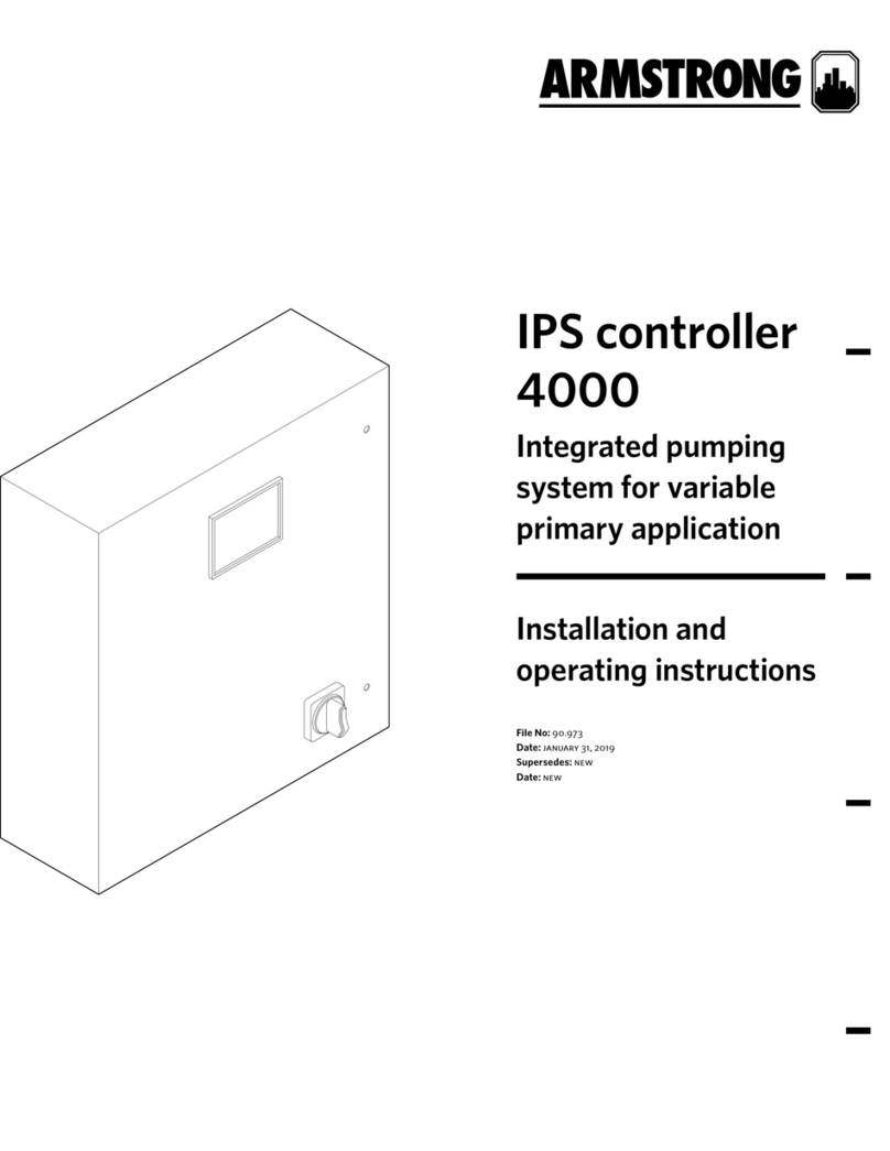
Armstrong 4000 User manual

IPS controller
4000
Integrated pumping
system for variable
primary application
Installation and
operating instructions
File No: 90.97
Date: december 15, 2015
Supersedes: new
Date: new


contents
1.0 ips controllers 4000 4
1.1 Installation instructions 4
1.2 Enviromental limits 4
1.3 Field devices installation instructions 4
1.4 Building automation system (bas)
connection 4
2.0 ips 4000 function displays 5
3.0 Operation displays 6
4.0 Setup displays 13
5.0 ips 4000 control system service lifecycle 23

installation &
operating instructions
ips 4000 controller - Integrated pumping
system for variable primary applications
4
Armstrong Integrated pumping system controllers, ips control-
lers 4000, are completely factory-assembled, tested, and
shipped to the job site as integral units ready to receive incom-
ing power supply. These instructions describe the procedures
to be followed during installation, commissioning and operation
to ensure optimum performance and reliability. When contact-
ing the factory for assistance, please provide the unit serial
number and other pertinent data, such as ips model no.
1.0 ips controllers 4000
1.1 installation instructions
Incoming supply – stand-alone ips controllers (no rack): The
incoming power supply should be brought in through the bot-
tom of the panel adjacent to the main terminals. Note that this
is the only electrical connection required at the panel.
The power supply voltage is 100-240 vac / 50-60 Hz as stan-
dard. Please refer to the wiring diagram supplied with the unit
for instructions on connecting power to the ips controller.
Incoming supply – ips system on rack: The incoming power
supply to the ips controller is achieved through a transformer
in the main enclosure of the whole ips system rack. No power
connection is required.
note: All electrical wiring should be performed by a qualified
electrician in accordance with the latest edition of the National
Electrical Code, local codes and regulations.
1.2 enviromental limits
Operation temperature range: 0°c to 50°c (32°f to 122°f)
(must not be exposed to direct sunlight)
Operation humidity range: (10% - 85%) non-condensing
Ambient air temperature for storage: -20°c to 70°c
(-4°f to 158°f)
1.3 field devices installation
instructions
Prior to using the display to configure the ips controller, make
sure all the field installed devices such as dp sensors, flow
sensors, dp switches are properly installed and wired to the ips
controller as per wiring diagrams provided.
1.4 building automation system
(bas) connection
When the ips controller is provided with a serial port to com-
municate serially to the bas, the possible communication
protocols are Modbus, LonWorks or BACnet. Refer to wiring
diagrams supplied with the unit for wiring instructions. ips
controller can also communicate to the bas through a hard
wired option. Please refer to the ips controller generic terminal
block diagram for the dierent parameters and data points
communicated to the bas. For more information please contact
your local Armstrong representative or Armstrong factory
service department.

installation &
operating instructions
ips 4000 controller - Integrated pumping
system for variable primary applications
5
2.0 ips 4000 function displays
The ips 4001 / 4002 / 4003 controllers displays are divided
in two set of displays: Operation and Setup. The Operation dis-
plays are used by the operators to monitor and control the ips.
The Setup screens are used to set, view, save, and restore the
system specific settings (i.e. number of pumps, chillers/boilers,
sensor range, etc.).
operation displays:
• Main menu
• System overview
• Zone overview
• Pump overview
• Sensorless overview
• Pump control
• Bypass valve overview
• Auto bypass reset
• Login
• Alarm overview
• Diagnostics
setup displays:
The setup displays are divided in three levels each with dier-
ent level of access. Level 0setup displays are for viewing only
and no adjustments can be made. Level 1setup displays can be
used for changing the system setup and restoring the system
factory defaults. Level 2setup displays can be used for chang-
ing the system setup, and saving and restoring the system
factory defaults. To access Level 1 and 2an operator need to
enter the proper password (please contact Armstrong factory
service department).
The list of setup/default displays for every level is as follow:
• System setup
• Zone setup
• Zone 1to 12 setup
• Sensorless setup
• Pump setup
• Speed setup
• Staging setup
• pid setup
• bas setup
• Clock setup
• Bypass valve setup
• System valves setup
• vfd readout setup
• Chiller/boiler 1to 6setup
• Flow setup

installation &
operating instructions
ips 4000 controller - Integrated pumping
system for variable primary applications
6
3.0 operation displays
3.1.0 main menu
Description
This is the screen the operator sees when powering up the
unit. It indicates status of the system’s most important vari-
ables, and also provides a means for the user to navigation to
all system screens
Data
ips status Indicates if the ips is on or o
Alarm If there is an alarm in the system, a red bell
appears at the top left corner
Buttons
rem – loc Slider button that allows changing the ips
mode to remote or local.
Local will turn on the ips immediately. Remote
causes the ips to follow the bas signal
(hard wired or serial communication) to turn
on or o
zone overview Changes the screen to Zone Overview. Not
available if the vfd type is ivs sensorless
bypass valve
overview
Changes the current screen to Bypass valve
Overview
system
overview
Changes the current screen to System
Overview
sensorless
overview
Changes the current screen to Sensorless
Overview. Only available if the sensorless
control is enabled
setup screen Navigates to the setup menu level zero screen
pump overview Navigates to the Pump Overview screen
alarm screen Shows the alarm screen. If there is an active
alarm, this button turns red
3.1.1 system overview
Description
Shows a detailed view of the system. The screen adapts to the
configuration of the system by showing the number of pumps
and chillers/boilers, the system flow , bypass valve, zone PVs
or head and flow. Press the xon the top right corner to go back
to the previous screen
Data
Chiller/boiler
1to 6status
The icons show the device status:
grey – stopped
green – running
Pump 1to 6status The pump icons shows the pump status:
grey – stopped
green – running
red - alarm
Pump 1to 6mode Shows each pump mode: Hand, O or Auto
Pump 1to 6duty Shows each pump duty: Duty1, Duty2, Duty3,
Duty4, Duty5, Duty6or Stand-by
Pump 1to 6speed Shows each pump speed in percentage
active zone Indicates which zone is assigned as Active.
Not visible if the vfd type is ivs sensorless
deviation Indicates the active zone deviation. Not vis-
ible if the vfd type is ivs sensorless
setpoint Indicates the active zone setpoint in the
chosen units. Not visible if the vfd type is ivs
sensorless and also system valves control is
disabled
max open vlv Indicates the opening of the driving sys-
tem valve. Not visible if the vfd type is ivs
sensorless and also system valves control is
disabled
flow Indicates both sensor and sensorless flow
values in the system based on the selection
head Indicates the total head in the system. Only
visible if the vfd type is ivs sensorless

installation &
operating instructions
ips 4000 controller - Integrated pumping
system for variable primary applications
7
delta Indicates how far from the control curve the
pump(s) are operating. The ips regulates the
pump speed to achieve an error of zero
ips status Indicates whether the ips is on or off
alarm A red bell indicates an Alarm in the system
bypass valve Indicates valve position in percentage (100%
means fully open)
minimum flow Indicates the rated minimum chiller/boiler
flow. Updates dynamically based on number
of chillers/boilers enabled
maximum flow Indicates the rated maximum chiller/boiler
flow. Updates dynamically based on number
of chillers/boilers enabled
Buttons
Pump 1to 6icon Touching a pump icon brings up the
corresponding pump control screen
3.1.2 zone overview
Description
Shows an overview of the system zones. If there are more than
3zones, use the grey arrows to scroll. This screen is not avail-
able if the vfd type is ivs sensorless
Data
actual Indicates the present value of the zone
sensor in the selected units
setpoint Indicates the setpoint of the zone in the
selected units
deviation Indicates the zone deviation in the
selected units
status Indicates whether the zone is enabled
or disabled
active zone Indicates which zone is assigned as active
active zone
deviation
Indicates the active zone deviation in the
selected units
Buttons
main menu Navigates to the main menu
system
overview
Changes the current screen to System
Overview
pump overview Changes the current screen to Pump Over-
view
alarms Shows the alarm screen. If there is an active
alarm, this button turns red
bypass overview Changes the current screen to Bypass
Overview
3.1.3 pump overview
Description
Allows monitoring pump information. If there are more than 3
pumps, scroll using the arrows on the top corners
Data
Pump 1to 6mode Shows each pump mode: Hand, O or Auto
Pump 1to 6
status 1
Shows each pump duty: Duty1, Duty2, Duty3,
Duty4, Duty5, Duty6or Stand-by
Pump 1to 6
status 2
Shows if the pump is running or stopped
Pump 1to 6
speed %
Shows each pump speed in percentage
Pump 1to 6
speed rpm
Shows each pump speed in rpm
Run hrs Shows the total pump run time in hours
auto bypass on If the pumps are in auto bypass, the auto by-
pass on label appears on the top left corner.
Touching this label brings up the auto bypass
reset screen

installation &
operating instructions
ips 4000 controller - Integrated pumping
system for variable primary applications
8
Buttons
Pump 1to 6Touching a pump button brings up the
corresponding pump control screen. If the
corresponding pump is in alarm, this button
changes to red color
main menu Navigates to the main menu
system overview Changes the current screen to System
Overview
sensorless
overview
Changes the current screen to Sensorless
Overview. Only available if the vfd type is ivs
sensorless
zone overview Navigates to the Zone Overview screen. Not
available if the vfd type is ivs sensorless.
alarms Shows the alarm screen. If there is an active
alarm, this button turns red
bypass overview Changes the current screen to Bypass
Overview
Scroll arrows If there are more than 3pumps in the system,
use the grey arrow buttons to scroll
3.1.4 sensorless overview
Description
This screen is only available when the vfd type is ivs sensor-
less, it complements the Pump Overview screen. If there are
more than 3 pumps, scroll using the arrows on the top corners
Data
Pump 1to 6mode Shows each pump mode: Hand, O or Auto
Pump 1to 6
status 1
Shows each pump duty: Duty1, Duty2, Duty3,
Duty4, Duty5, Duty6or Stand-by
Pump 1to 6
status 2
Shows if the pump is running or stopped
flow Indicates the current flow of that pump in the
selected units
head Indicates the current head of that pump in
the selected units
total flow Indicates the system flow in the selected
units
total head Indicates the system head in the selected
units
Buttons
Pump 1to 6Touching a pump button brings up the
corresponding pump control screen. If the
corresponding pump is in alarm, this button
changes to red color
main menu Navigates to the main menu
system overview Changes the current screen to System
Overview
pump overview Changes the current screen to Pump
Overview
alarms Shows the Alarm Screen. If there is an active
alarm, this button turns red
bypass overview Changes the current screen to Bypass
Overview
Scroll arrows If there are more than 3pumps in the system,
use the grey arrow buttons to scroll
3.1.5 pump 1 to 6 control
Description
This screen allows control of each pump and shows more
detailed information. Press the xon the top right corner to go
back to the previous screen
Data
mode Shows pump mode: Hand, O or Auto
status 1 Shows pump duty: Duty1, Duty2, Duty3,
Duty4, Duty5, Duty6or Stand-by
status 2 Shows if the pump is running or stopped
pump alm Indicates if there is a pump alarm
drv fault Indicates if the vfd is reporting a fault
installation &
operating instructions
ips 4000 controller - Integrated pumping
system for variable primary applications
9
run hrs Indicates the pump total run time in hours.
Touching the run hrs label opens a dialog
window to confirm resetting the total run
hours
lead pump switch Indicates the remaining time in days or hours
to switch the Duty1(Lead) pump
speed (%) Shows pump speed in percentage
speed (rpm) Shows pump speed in rpm
current (a) Shows the vfd current
volts (vac) Shows the vfd ac voltage
power (kw) Shows the vfd power in kWs
speed bars Show the pump speed reference and actual
speed in a graphical manner
auto bypass on If the pump is in auto bypass, the auto
bypass on label appears on the bottom of
the screen. Touching this label brings up the
auto bypass reset screen
Alarm If there is a pump alarm, a red bell appears at
the top right corner
Buttons
lead Assigns the pump as Duty1or Lead
hand Changes the pump mode to hand. If the ips is
on, the pump will start immediately and run
at the hand speed (see below)
off Changes the pump mode to o. The pump
will stop immediately and it will be excluded
from the duty rotation
auto Changes the pump mode to auto. The pump
will be assigned a duty status and it will run
according to the ips control algorithm
hand speed If the pump is placed in hand, it will run at
the hand speed entered
3.1.6 bypass valve overview
Description
This screen allows monitoring of the Bypass Valve Overview
feature
Data
position (%) Indicates valve position in percentage (100%
means fully open)
actual flow pv Displays system flow. Obtained from flow
meter or from sensorless readout depending
on the selection
minimum flow Indicates rated minimum chiller/boiler flow.
Updates dynamically based on number of
chillers/boilers enabled
maximum flow Indicates rated maximum chiller/boiler flow.
Updates dynamically based on number of
chillers/boilers enabled
Buttons
mode select Allows user to select the operation mode
manual or auto
hand position If manual mode is selected, the user can
enter the desired valve position
main menu Navigates to the main menu
system
overview
Changes the current screen to System
Overview
pump overview Changes the current screen to Pump
Overview
alarms Shows the alarm screen. If there is an
active alarm, this button turns red
zone overview Changes the current screen to Zone Overview
main menu Navigates to the main menu

installation &
operating instructions
ips 4000 controller - Integrated pumping
system for variable primary applications
10
3.1.7 auto bypass reset
Description
This screen allows the operator to reset the pump auto bypass
condition. Press the x on the top right corner to go back to the
previous screen
Buttons
yes Resets the auto bypass. If the conditions that caused
the auto bypass don’t exist anymore, the pumps will
resume normal operation
no Closes the auto bypass reset screen and returns to the
previous screen
3.1.8 login screen
Description
This screen allows the operator to login to the desired level by
providing the appropiate password
Data
password Shows the encoded password. Touching
it brings up a numeric keypad to enter the
password
Buttons
login If the password entered is valid, touching this
button will change the screen to the setup
menu of the corresponding level
logout Changes the screen back to the main menu
3.1.9 alarm screens
Description
This screen shows the current alarms in the system. Press the
xon the top right corner to go back to the previous screen
Data
Select Select the alarm in order to be acknowledged
and reset
Description Shows the description of the alarm. The possible
alarms are shown below in section 1.2.1
State Provides information about two alarm conditions:
1 Triggered or Not Triggered (Triggered
means that the condition that generates
the alarm is still present, the alarm can be
acknowledged but not reset)
2 Acknowledged or Not Acknowledged
Buttons
reset Resets the alarms.
In order to clear from the list see Reset button
below
diagnostic Brings up the plc diagnostics screen
history Brings up the alarm history screen
Check/
Uncheck
Selects/unselect the alarms. Only selected
alarms can be acknowledged and cleared from
the list
filter Not used
ack Acknowledges the selected alarms
Clear Clears the selected alarms that are not
triggered
Save Not used

installation &
operating instructions
ips 4000 controller - Integrated pumping
system for variable primary applications
11
Description
This screen shows the alarms history. Press the xon the top right
corner to go back to the previous screen
Data
Description Shows the description of the alarm. The possible
alarms are shown below in section 1.2.1
Time Shows the time of occurrence of each alarm
Buttons
refresh Refreshes the alarm list
Duration Drop down menu that allows to filter the list of
alarms based on time of occurrence
Previous Shows alarm history from the previous period
selected in the duration dropdown menu
Next Shows alarm history from the next period se-
lected in the duration dropdown menu
3.1.10 plc diagnostic
Description
This screen shows the current state of the plc and the software
revisions installed. Press the xon the top right corner to go back
to the previous screen
Data
plc Indicates if the plc is working properly
network Indicates if the plc network is working properly
memory Indicates if the plc memory is working properly
comm Indicates if the serial communication port of the plc is
working properly
plc rev Indicates the software revision installed on the plc
hmi rev Indicates the software revision installed on the hmi

installation &
operating instructions
ips 4000 controller - Integrated pumping
system for variable primary applications
12
3.2.1 alarms
Alarm Description Possible causes
Pump n alarm Indicates that pump n is in alarm Any pump alarm will trigger this alarm
Pump n run feedback alarm
Indicates that the plc didn’t detect the pump
run feedback after commanding the pump to
start
• vfd not configured for serial communication
• Loose or broken wire from vfd
• Incorrect vfd type selected on ips
• Impeller is stuck
Pump n no flow alarm
Indicates that the plc didn’t detect flow (dp
switch not closed) after commanding the
pump to start
• dp switch not correctly adjusted
• Loose or broken wire
• Damaged plc digital input
• Impeller is stuck
Pump n drive fault alarm Indicates that the pump vfd is reporting a fault vfd over current or other problem. Check vfd local display
dp transmitter fail alarm Indicates that the dp transmitter is out of range
• Connection to transmitter is short or open circuited
• Damaged plc analog input
• Loose or broken wire from transmitter
• Damaged transmitter
Flow transmitter fail alarm Indicates that the flow transmitter is out
of range
• Connection to transmitter is short or open circuited
• Damaged plc analog input
• Loose or broken wire from transmitter
• Damaged transmitter
Zone n transmitter alarm Indicates that the zone transmitter is out
of range
• Connection to transmitter is short or open circuited
• Damaged plc analog input
• Loose or broken wire from transmitter
• Damaged transmitter
All zones transmitter alarm Indicates that all zones transmitters are out
of range All zone sensors are in alarm
Pump n flow deviation alarm Indicates that the sensorless flow of the pump
is 20% o the average of the running pumps
• There is a problem with the sensorless mapping of
the vfd
• Air in the system
• A manual valve is obstructing the flow
Chiller/boiler flow below
minimum alarm
Indicates system flow is less than chiller/boiler
total minimum set value
• Incorrect calibration of flow meter
• Bypass valve not open
• Flow obstruction in the pipe
Chiller/boiler flow above
maximum alarm
Indicates system flow is greater than chiller/
boiler total maximum set value
• Incorrect calibration of flow meter
• Bypass valve not close
• Incorrect design sensorless data

installation &
operating instructions
ips 4000 controller - Integrated pumping
system for variable primary applications
13
4.0 setup displays
The setup displays allow viewing, modifying, saving and
restoring system parameters. There are 3levels of password
protected access:
Level Actions allowed
Level 0 • View only
Level 1 • Modify all parameters
• Restore previously saved default values (factory
defaults); expect Pump pid and bas parameters
Level 2 • Modify all parameters
• Save changes
• Restore previously saved default values
(factory defaults)
The following sections list and describe each setup screen.
Only Level 2 screens are shown, however each level has the
same screens with their respective level restrictions.
4.1.0 level 2 setup menu
Description
This screen allows navigation to each of the setup screens
Button
pump setup Navigates to the pump setup screen
zone setup Navigates to the zone setup screen. Not
available if the vfd type on pump setup
screen is ivs sensorless
sensorless setup Navigates to the sensorless setup screen.
Not available only if the vfd type on pump
setup screen is ivs sensorless
speed setup Navigates to the pump speed setup screen
eoc setup Navigates to the end of curve (eoc) protec-
tion screen
bep setup Navigates to the duty speed staging setup
screen
pid setup Navigates to the pid setup screen
bas setup Navigates to the bas setup screen
clock setup Navigates to the clock setup screen
bypass valve
setup
Navigates to the bypass valve setup screen
system vlv setup Navigates to the system valves setup screen
vfd readout
factors
Navigates to the vfd readout factors setup
screen
flow setup Navigates to the flow setup screen
main menu Returns to the main menu. User must login
again to return to the level 1& level 2 setup
menu
save Saves all the current setup parameters as
default. Only available in level 2
restore Restores all the default parameters as de-
fault. Only available in level 1 & 2
ips model Selects the ips model: 4001, 4002 or 4003.
Only available in level 1 &2
4.1.1 zone setup
Parameter: no of zones
Range: Function:
1-12 Indicates how many zones will be used to control the
system, typically one zone per area of the building
Parameter: eng. unit
Options: Function:
psi dp sensors in psi are used
ft dp sensors in ft are used
kPa dp sensors kPa psi are used
mdp sensors in m are used
bar dp sensors in bar are used
°f Temperature sensors in °fare used
°c Temperature sensors in °care used

installation &
operating instructions
ips 4000 controller - Integrated pumping
system for variable primary applications
14
Button: save
Range: Function:
n/a Saves current parameters as default. Only available in
level 2
Button: restore
Range: Function:
n/a Restores default parameters. Only available in levels
1 &2
4.1.2 zone 1 to 12 setup
There is one screen per zone
Parameter: range
Range: Function:
0.0-999.9
(psi, ft, kPa, m,
bar, °f, °c)
Indicates the range of the dp or Temperature
sensor of the zone
Parameter: setpoint
Range: Function:
0.0-999.9 (psi,
ft, kPa, m, bar,
°f, °c)
Indicates the setpoint of the zone. The ips uses
this value to determine the pump speed
Parameter: setpoint
Option: Function:
Disable The zone is disabled, it won’t be used to deter-
mine the active zone and pump speed
Enable The zone is enabled, it will be used to determine
the active zone and pump speed
Button: save
Range: Function:
n/a Saves current parameters as default. Only
available in level 2
Button: restore
Range: Function:
n/a Restores default parameters. Only available in
levels 1 &2
4.1.3 pump setup
Parameter: no of zones
Range: Function:
1-6 Indicates how many pumps are installed in the system
Parameter: stndby pump
Options: Function:
no All pumps in the system are duty
yes One of the pumps in the system will be assigned as
standby, it will only operate if a duty pump fails and
there is no other duty pump to replace it. Rotation of
duty 1pump also rotates the standby pump to achieve
even hours of operation
Parameter: auto bypass
Options: Function:
disable Auto bypass function is disabled
enable When a pump fails (due to no run feedback, vfd fault
or communication), the ips will determine if there is
another pump available to replace the faulty pump.
If there is no pump available, a digital output will
mechanically bypass the vfd and energize the pump
motor directly. All pumps running at that moment will
be bypassed
Parameter: switch time
Range: Function:
1-999
(Days,
Hours)
Indicates how often the lead (duty 1) pump will rotate
among the duty pumps
Parameter: min run time
Range: Function:
1-999
minutes
Indicates what is the minimum time the lead (duty 1)
pump will run once it is started

installation &
operating instructions
ips 4000 controller - Integrated pumping
system for variable primary applications
15
Parameter: vfd comm.
Options: Function:
disable No serial communication to vfds. The ips will use
hardwired connections
enable The ips uses serial communication to the vfds.
Select if the vfd power is 50 or 60 hz. The available
vfds are listed below
Parameter: drive type
Options: Function:
ivs Serial communication to Armstrong ivs drive
ach 550 Serial communication to abb ach 550 drive
fc 102 Serial communication to Danfoss fc102 drive
e7 Serial communication to Yaskawa e7 drive
ivs
(sensor-
less)
Serial communication to Armstrong ivs drive config-
ured for sensorless operation. By selecting this option
the ips4000 will operate in parallel sensorless mode
*note: The ips4000 is configured to communicate to the drives with the following
parameters: Modbus rtu, 19200 baud, no parity, 8bits 1stop bit
Parameter: fbus source
Options: Function:
fbus1 This is the default. The plc utilizes the field card in the
fieldbus card slot to communicate with the vfds
fbus2 The plc utiizes port j26 fbus2 to communicate with
the vfds. This option can be used if the field card is
damaged (this option is not available for ips4003)
Button: save
Range: Function:
n/a Saves current parameters as default. Only available in
level 2
Button: restore
Range: Function:
n/a Restores default parameters. Only available in
levels 1 &2
4.1.4 speed setup
Parameter: min speed
Range: Function:
0.0-100.0% The minimum speed the pumps will be allowed to
run in Auto or Hand mode
Parameter: max speed
Range: Function:
0.0-100.0% The maximum speed the pumps will be allowed
to run in Auto or Hand mode
Parameter: default speed
Range: Function:
0.0-100.0 % Indicates the speed the pumps will run at if all
zone sensors fail. It does not apply in sensorless
mode
Parameter: rated rpm
Range: Function:
0-9999 rpm The pump rated rpm as indicated on the motor
nameplate
Parameter: ramp
Range: Function:
1-999 sec Indicates the amount of time it will take the
pumps to increase their speed from 0% to 100%
or to decrease their speed from 100% to 0%
Button: save
Range: Function:
n/a Saves current parameters as default. Only avail-
able in level 2
Button: restore
Range: Function:
n/a Restores default parameters. Only available in
levels 1 &2
4.1.5 sensorless setup

installation &
operating instructions
ips 4000 controller - Integrated pumping
system for variable primary applications
16
Parameter: flow bep
Range: Function:
0-20000 Flow at bep (Best Eciency Point) for one pump. It
is used in conjuction with head bep to stage pumps
on and o in order to maintain the system operat-
ing eciently. For more information please contact
your local Armstrong representative
Parameter: head bep
Range: Function:
0.0-9999.9 Head at bep (Best Eciency Point) for one pump.
It is used in conjuction with flow bep to stage
pumps on and o in order to maintain the system
operating eciently. For more information please
contact your local Armstrong representative
Parameter: dead band
Range: Function:
0.0 to 1.0 It is used to prevent constant staging of pumps.
For more information please contact your local
Armstrong representative
Parameter: head unit
Options: Function:
ft The drive sensorless head is programmed in ft
psi The drive sensorless head is programmed in psi
kPa The drive sensorless head is programmed in kPa
mThe drive sensorless head is programmed in m
bar The drive sensorless head is programmed in bar
Parameter: sens adj
Range: Function:
0 - 5 It is used to adjust the sensorless mapping of the
vfd. For more information please contact your
local Armstrong representative
Parameter: flow design
Range: Function:
0 - 20000 Pump Design Flow. It is used to determine the
system control curve
Parameter: head design
Range: Function:
0.0 -
9999.9
Pump Design Head. It is used to determine the
system control curve
Parameter: zero flow head
Range: Function:
0.0 -
9999.9
Pump Head at zero flow. It is used to determine
the system control curve
Parameter: flow unit
Options: Function:
gpm The drive sensorless flow is programmed in gpm
L/s The drive sensorless flow is programmed in L/s
m3/h The drive sensorless flow is programmed in m3/h
Button: auto select
Options: Function:
auto
select
Opens up the pump selection popup window (see
below) to allow user to enter pump selection data
and automatically populate the sensorless operation
parameters
manual
select
By selecting this option, the user manually enters
data on the sensorless operation parameters
Button: select pump
Options: Fucntion:
n/a When in auto select mode (see button above), this
buttons opens up the pump selection popup window
if it is necessary to edit the pump selection data
Button: save
Range: Function:
n/a Saves current parameters as default. Only available
in level 2
Button: restore
Range: Function:
n/a Restores default parameters. Only available in levels
1 &2
4.1.5.1 pump selection
Parameter: series
Options: Function:
4300 Selects pump series 4300
4302 Selects pump series 4302
Parameter: poles
Range: Function:
2 to 8 Select the pump number of poles
Parameter: size
Range: Function:
n/a Enter the pump size: Suction, Discharge and Nomi-
nal Impeller size. Then select whether the pump is
low (L) or high (H) flow

installation &
operating instructions
ips 4000 controller - Integrated pumping
system for variable primary applications
17
Parameter: imp dia
Range: Function:
n/a Enter the pump impeller diameter and units
(inch or mm)
Button: validate selection
Range: Function:
n/a Based on the pump data entered, selects pump
design and bep data and populates the correspond-
ing parameters on the sensorless setup screen. If
the pump data entered is invalid an error message is
displayed
4.1.6 eoc setup
Parameter: type
Options: Function:
dp eoc (End of Curve) protection is achieved with a dp
sensor
flow eoc protection is achieved with a flow sensor or
with the sensorless flow if available
Parameter: status
Options: Function:
disabled eoc protection is disabled
enabled eoc protection is enabled. If the dp or flow of one
pump exceeds the eoc setpoint (see below), the
next lag pump will be immediately staged on
Parameter: range
Range: Function:
0 - 999.9 Indicates the range of the dp sensor in engineering
units. This value corresponds to the sensor’s 20mA
output
Parameter: flow
Range: Function:
0 - 20000 Indicates the pump’s flow eoc setpoint. If the read-
ing from the sensor exceeds this value, the next lag
pump is staged on
Parameter: dp
Range: Function:
0-20000 Indicates the pump’s dp eoc setpoint. If the reading
from the sensor combined with the pump speed is
below this value, the next lag pump is staged on
Button: save
Range: Function:
n/a Saves current parameters as default. Only avail-
able in level 2
Button: restore
Range: Function:
n/a Restores default parameters. Only available in
levels 1 &2
4.1.7 staging setup
Parameter: stage up duty2
Range: Function:
0.0 –
100.0%
Determines the Duty1pump speed at which the
Duty2pump will be staged on. (Not available for
ivs sensorless drives)
Parameter: stage up duty3
Range: Function:
0.0 -
100.0 %
Determines the Duty1pump speed at which the
Duty3pump will be staged on. (Not available for
ivs sensorless drives)
Parameter: stage up duty4
Range: Function:
0.0 -
100.0 %
Determines the Duty1 pump speed at which the
Duty4pump will be staged on. (Not available for
ivs sensorless drives)
Parameter: stage up duty5
Range: Function:
0.0 -
100.0 %
Determines the Duty1pump speed at which the
Duty5pump will be staged on. (Not available for
ivs sensorless drives)

installation &
operating instructions
ips 4000 controller - Integrated pumping
system for variable primary applications
18
Parameter: stage up duty6
Range: Function:
0.0 -
100.0 %
Determines the Duty1pump speed at which the
Duty6 pump will be staged on. (Not available for
ivs sensorless drives)
Parameter: stage down duty2
Range: Function:
0.0 -
100.0 %
Determines the Duty1pump speed under which
the Duty2pump will be staged o. (Not available
for ivs sensorless drives)
Parameter: stage down duty3
Range: Function:
0.0 -
100.0 %
Determines the Duty1pump speed under which
the Duty3pump will be staged o. (Not available
for ivs sensorless drives)
Parameter: stage down duty4
Range: Function:
0.0 -
100.0 %
Determines the Duty1pump speed under which
the Duty4pump will be staged o. (Not available
for ivs sensorless drives)
Parameter: stage down duty5
Range: Function:
0.0 -
100.0 %
Determines the Duty1pump speed under which
the Duty5pump will be staged o. (Not available
for ivs sensorless drives)
Parameter: stage down duty6
Range: Function:
0.0 -
100.0 %
Determines the Duty1pump speed under which
the Duty6pump will be staged o. (Not available
for ivs sensorless drives)
Parameter: stage on delay
Range: Function:
0.0 -
999 sec
Determines the time delay before staging on the
next lag pump once the conditions are met. It ap-
plies to all drives, including ivs sensorless
Parameter: stage off delay
Range: Function:
0.0 -
999 sec
Determines the time delay before staging o the
last lag pump once the conditions are met. It ap-
plies to all drives, including ivs sensorless
Button: save
Range: Function:
n/a Saves current parameters as default. Only avail-
able in level 2
Button: restore
Range: Function:
n/a Restores default parameters. Only available in
levels 1 &2
4.1.8 pid setup
Parameter: Kc
Range: Function:
0-9999 Determines the pump speed control pid loop gain.
Smaller values correspond to a more responsive
controller
Parameter: Ti
Range: Function:
0-999 Determines the pump speed control pid loop
integral time. Larger values correspond to more
iterations and reduction of steady state error
Parameter: Td
Range: Function:
0-999 Not used
Parameter: type (Only appears when zone units are set on
temperature)
Options: Function:
cool Active zone is the zone with the largest deviation.
Pump speed increases if the zone temperature
increases
heat Active zone is the zone with the smallest deviation.
Pump speed decreases if the zone temperature
increases
Button: save
Range: Function:
n/a Saves current parameters as default. Only available
in level 2
Button: restore
Range: Function:
n/a Restores default parameters. Only available in
levels 1 &2

installation &
operating instructions
ips 4000 controller - Integrated pumping
system for variable primary applications
19
4.1.9 clock setup
Parameter: hh
Range: Function:
0 - 24 Sytem clock hour
Parameter: mm
Range: Function:
0 - 60 Sytem clock minute
Parameter: dd
Range: Function:
1 - 31 Sytem clock day
Parameter: mm
Range: Function:
1 - 12 Sytem clock month
Parameter: yy
Range: Function:
00 – 99 Sytem clock year
4.1.10 bypass valve setup
Parameter: Kc
Range: Function:
0-9999 Determines the valve control pid loop gain. Smaller
values correspond to a more responsive controller
Parameter: Ti
Range: Function:
0-999 Determines the valve control pid loop integral time.
Larger values correspond to more iterations and
reduction of steady state error
Parameter: valve output
Options: Function:
0 – 10 vdc 0 vdc commands the valve as fully closed. 10 vdc as
fully open
2 – 10 vdc 2 vdc commands the valve as fully closed. 10 vdc as
fully open
Parameter: minimum position
Range: Function:
0.0 - 100.0 Minimum position the valve is allowed to
Parameter: maximum position
Range: Function:
0.0 - 100.0 Maximum position the valve is allowed to
Parameter: open setpoint
Range: Function:
0.0 - 100.0 When system flow is under the chiller/boiler
minimum and the bypass valve is open at this
percentage (or above), the pumps will ramp up to
maximum speed
Parameter: close setpoint
Range: Function:
0.0 - 100.0 When the system flow is under the chiller/boiler
minimum and the bypass valve is closing and
reaches this percentage (or below) the pumps
return to their normal speed

installation &
operating instructions
ips 4000 controller - Integrated pumping
system for variable primary applications
20
Button: save
Range: Function:
n/a Saves current parameters as default. Only available
in level 2
Button: restore
Range: Function:
n/a Restores default parameters. Only available in levels
1 &2
4.1.11 bas communication setup
Parameter: protocol
Options: Function:
n/a No bas protocol is selected
Modbus Selects Modbus rtu
Lonworks Selects Lonworks
BACnet Selects BACnet
Parameter: address
Range: Function:
0-127 Selects the ips bas address. Only applies to Modbus
protocol
Parameter: baud rate
Options: Function:
1200 Selects 1200 as baud rate. Only applies to Modbus
protocol
2400 Selects 2400 as baud rate. Only applies to Modbus
protocol
4800 Selects 4800 as baud rate. Only applies to Modbus
protocol
9600 Selects 9600 as baud rate. Only applies to Modbus
protocol
19200 Selects 19200 as baud rate. Only applies to Modbus
protocol
Button: save
Range: Function:
n/a Saves current parameters as default. Only available
in level 2
Button: restore
Range: Function:
n/a Restores default parameters. Only available in levels
1 &2
Table of contents
Other Armstrong Controllers manuals

Armstrong
Armstrong DRV40 User manual

Armstrong
Armstrong 80-DC Series User manual

Armstrong
Armstrong AVR 235 User manual

Armstrong
Armstrong 20-DC Series User manual

Armstrong
Armstrong 3750 User manual

Armstrong
Armstrong IVS 102 Operating instructions

Armstrong
Armstrong 3760 ProDose Series User manual

Armstrong
Armstrong OB-31 User manual

Armstrong
Armstrong Emech G1 Instruction manual

Armstrong
Armstrong IPS 4000 User manual