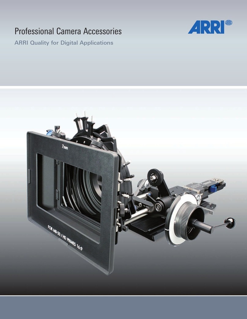
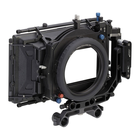
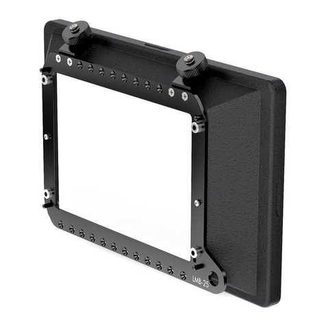
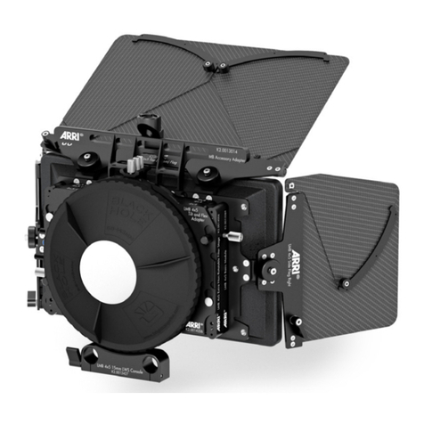
ARRI SMB-1 User manual

STUDIO MATTE BOX SMB-1
U S E R G U I D E
17 December 2014
STUDIO MATTE BOX SMB-1
U S E R G U I D E
17 December 2014

2 Imprint
Imprint
Copyright
© 2014 Arnold & Richter Cine Technik GmbH & Co. Betriebs KG. All rights reserved.
No portions of this document may be reproduced without prior written consent of
Arnold & Richter Cine Technik GmbH & Co. Betriebs KG. Specifications are subject to
change without notice. Errors, ommissions, and modifications excepted.
Original version.
For further assistance
Arnold & Richter Cine Technik GmbH & Co. Betriebs KG
Tuerkenstr. 89
D-80799 Munich, Germany
E-mail: [email protected]
www.arri.com/service
Document revision history
Version
1.0
ID
80.0003786
Release
K08575
Date
17 December 2014

Contents 3
Contents
1 Risk levels and alert symbols..............................................................5
2 Introduction............................................................................................ 6
3 Available versions................................................................................. 7
4 Accessories............................................................................................8
5 Compatibility........................................................................................ 11
6 Tooling.................................................................................................. 12
7 Sunshade..............................................................................................13
7.1 Mounting/Removing a sunshade.........................................................13
7.2 Anamorphic sunshade.........................................................................14
8 Swing-away system.............................................................................15
8.1 Opening a matte box with swing-away system................................... 15
9 Studio Arm........................................................................................... 16
9.1 Mounting/Removing a matte box studio arm...................................... 16
9.2 Fitting a matte box on rods................................................................. 17
10 Filter stages......................................................................................... 18
10.1 Fitting a group of filter stages............................................................. 18
10.2 Separating two filter stages.................................................................19
10.3 Rotating the filter stages..................................................................... 20
10.4 Geared filter frame.............................................................................. 21
10.5 Tray catcher.........................................................................................22
11 Tilt and extension module..................................................................23
11.1 Tilt module........................................................................................... 23
11.2 Extension module................................................................................ 24
12 Flags......................................................................................................25
12.1 Mounting/Removing the top/bottom flag..............................................25
12.2 Mounting/Removing a side flag...........................................................26
12.3 Adjusting the flag angle.......................................................................26
12.3.1 Quick adjust.........................................................................................27
12.3.2 Fine adjust........................................................................................... 27
13 Mattes....................................................................................................28
13.1 Inserting a matte................................................................................. 28
13.2 Fitting a protective cover (matte #0)................................................... 29

4 Contents
14 Accessory adapter.............................................................................. 30
14.1 Mounting/Removing an accessory adapter......................................... 30
14.2 Adapter operation................................................................................ 31
15 6" Tilting filter ring.............................................................................. 32
15.1 Mounting/Removing the 6" tilting filter ring..........................................32

Risk levels and alert symbols 5
1 Risk levels and alert symbols
Safety warnings, safety alert symbols, and signal words in these instructions indicate
different risk levels:
CAUTION!
CAUTION indicates a potentially hazardous situation which, if not avoided, may
result in minor or moderate injury.
NOTICE
NOTICE explains practices not related to physical injury. No safety alert symbol
appears with this signal word.

6 Introduction
2 Introduction
The Studio Matte Box SMB-1 supports filter sizes up to 6.6" x 6.6". It is designed for
use with bigger wide-angle prime lenses and also with zooms.
The SMB-1 Tilt has an exclusive integrated tilt module and all versions benefit from
stackable filter stages, allowing quick reconfiguration.
Uniquely, both 4:3 and 2:1 ratio sunshades are available, optimized respectively for
spherical and anamorphic filming.
The Studio Matte Box SMB-1 covers the full ALEXA sensor area and allows the
Master Prime 12 mm to be used with a 2-filter stage, the Ultra Prime 10 mm with a 1-
filter stage, and the Ultra Wide Zoom UWZ 9.5-18 mm with a 1-filter stage.

Available versions 7
3 Available versions
1
2
1SMB-1 Tilt K2.66262.0
2SMB-1 Basic K2.0001516

8 Accessories
4 Accessories
1
2
3
5
4
1Extension Module K2.0001519
2Tilt and Extension Module K2.0001520
3Top/Bottom Flag K2.66273.0
4Side Flags (pair) K2.66274.0
5Side Flags ANAM (pair) K2.0001173

Accessories 9
1
2
3
4
5
6
11-Filter Stage incl. 1 x Filter Frame, non-
geared K2.0001462
22-Filter Stage incl. 1 x Filter Frame, non
geared and 1 x Filter Frame, geared K2.0001465
3Sunshade ANAM K2.0001466
4Mattes SPH K2.66267.0
5Mattes SPH/ANAM K2.0001161
6Mattes ANAM K2.0000676

10 Accessories
1
2
3
4
7
6
5
16" Tilting Filter Ring Ø150 mm K2.0001174
219 mm Studio Arm K2.66280.0
315 mm Studio Arm K2.0000646
4Case for SMB-1 K2.0002669
5Accessory Adapter K2.0001172
6Flexible Shaft K2.34890.0
7Top/Bottom Flag Holders (pair) K2.0001517

Compatibility 11
5 Compatibility
The Studio Matte Box is compatible with the following ARRI accessories:
•All R1 rings 165 mm - check details online with ARRI Configuration Overviews
•All F1 filter frames - check details online with ARRI Configuration Overviews

12 Tooling
6 Tooling
NOTICE
All fastening screws necessary for matte box operation are fitted with a 3 mm Hex
driver.
The dismantling of matte box components fastened with Torx head screws is not
covered in this manual. We recommend contacting an ARRI Service partner.
Tools needed
•1 x 3 mm Hex driver

Sunshade 13
7 Sunshade
The sunshade of the matte box can be removed for special applications.
An optional sunshade designed for anamorphic filming is available (K2.0001466). This
sunshade is part of the Anamorphic Upgrade Set (K0.0001676).
7.1 Mounting/Removing a sunshade
Remove the sunshade in order to fit the anamorphic sunshade or for special
applications when no sunshade is desired, such as with macro shots.
1
2
1
1. Fit the matte box to the camera rods or rest the matte box on its back.
2. To remove: Hold the sunshade (2) to the matte box and loosen all six screws (1).
Note: The screws (1) should stay captive in the sunshade (2).
3. Remove sunshade (2).
4. To mount: Tighten all six screws (1).

14 Sunshade
7.2 Anamorphic sunshade
You can optimize the matte box for anamorphic filming with a 2:1 ratio sunshade, side
flags and matte set. The standard 4:3 ratio sunshade covers the full ALEXA sensor
and permits repositioning in post-production.
The optional Anamorphic Upgrade Set comprises a 2:1 ratio sunshade, a pair of side
flags and a set of mattes matching the 2:1 ratio sunshade.
SMB-1 Anamorphic Upgrade Set K0.0001676
Sunshade ANAM K2.0001466
Side Flags ANAM (pair) K2.0001173
Mattes ANAM K2.0000676
NOTICE
Each flag holder for the top and bottom flag can be repositioned by means of the
two screws holding it to the matte box main frame in order to suit either the 4:3 or
2:1 sunshade.

Swing-away system 15
8 Swing-away system
To facilitate lens change, you can open the matte box. The swing-away system locks
automatically in a closed and opened position. This reduces the probability of lens
damage during lens change.
8.1 Opening a matte box with swing-away system
1
1. Fit the matte box to the camera rods.
2. If necessary, ease the lens rubber ring off the lens. Alternatively, extend the matte
box with the extension module. See Page 24.
3. Pull the release plunger (1) while opening the matte box to the right of the camera
until it locks automatically.
4. Change or clean the lens.
5. Pull the release plunger (1) and swing the matte box back onto the lens until it
locks automatically.
6. Adjust the matte box extension if necessary.

16 Studio Arm
9 Studio Arm
The Studio Matte Box is available with 19 mm and 15 mm matte box studio arms.
NOTICE
The matte box can only be supported on 19 mm and 15 mm studio rod systems. A
15 mm lightweight support is not compatible.
9.1 Mounting/Removing a matte box studio arm
1
2
1. Rest the matte box on its sunshade.
2. Unlock the extension module (1).
3. Extend the matte box by rotating the extension knob (2) clockwise.
4. To remove: If fully extended, gently seperate the matte box and arm.
5. To mount: Insert the matte box arm by rotating the extension knob (2) anti-
clockwise and adjust the matte box extension if necessary.

Studio Arm 17
9.2 Fitting a matte box on rods
The Studio Matte Box fits 19 mm or 15 mm studio camera systems.
4
5
1
2
3
NOTICE
Before fitting the matte box, install all rod-related accessories. Please ensure that
fitting the matte box is the last step.
1. Unlock the studio arm console by turning the wheel (5) anti-clockwise.
2. Slide the matte box onto the rods (4) with the extension closed.
3. Lock both rods and the matte box by turning the wheel (5) clockwise.
4. You can now raise or lower the matte box:
– Loosen the 3 mm hex screw (2) on top of the arm
– Turn the height adjuster (3) with the same driver until you reach the
required height
– To reset to standard height: Align the white line on the adjuster (3) with the
clamp slot (1) on top of the matte box arm

18 Filter stages
10 Filter stages
SMB-1 filter stages come in 1-filter and 2-filter modules.
•1-filter stage modules come with one filter frame 6.6" x 6.6" (non-geared) and
cannot accept geared filter frames.
•2-filter stage modules come with two filter frames (one geared, one non-
geared).
All filter stages are fitted with tray catchers.
All filter frames, non-geared, are compatible with the geared slot of the 2-filter stage.
NOTICE
You can remove filter stages as a single module or in group.
10.1 Fitting a group of filter stages
1
3
4
2
1. Remove the back plate (4) from the matte box if necessary:
°Release the relevant release plunger (2)
°Pull the back plate (4) upwards
2. Slide the group of filter stages (1) from the top of the matte box:
°Ensure that all sliding guides (3) are fully engaged in their counterparts
3. Slide the filter stages (1) down until the release plunger (2) clicks.
4. Fit the back plate (4) at the back of the rear filter stage (1).

Filter stages 19
10.2 Separating two filter stages
1
2
1. Pull the respective release plunger (1) .
2. Lift up and remove the redundant filter stage.
3. Reattach the back plate (2) to the remaining filter stage.

20 Filter stages
10.3 Rotating the filter stages
The filter stages can rotate independently. Note: Filter frames in 2-filter stages rotate
in pairs.
NOTICE
The filter stage features an anti-friction coating and should not be greased or oiled.
1
1. Fit the matte box to the camera rods.
2. Install the filter stages to the matte box.
3. Unlock the filter stage rotation by turning the rotation lock (1) anti-clockwise
slightly.
4. Rotate the filter stage to the required angle.
5. Lock the filter stage rotation by turning the rotation lock (1) clockwise.
Table of contents
Other ARRI Camera Accessories manuals