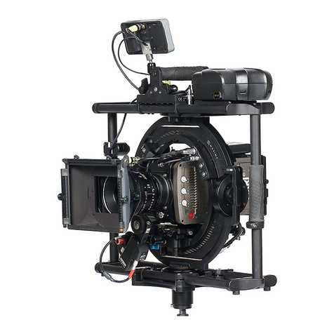
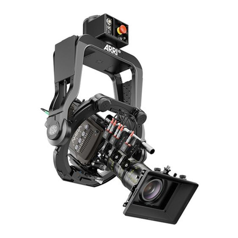
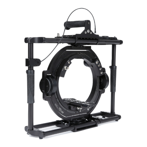
ARRI SRH-3 User manual

!
!
Stabilized Remote Head
SRH-3 SUP 2.2!
!
!
!
!
!
Date 01.08.2019!
!
!
!
Manual

!2
!
Imprint
!
Copyright © 2019 Arnold & Richter Cine Technik GmbH & Co. Betriebs Kg.
All rights reserved.
No parts of this document may be reproduced without prior written consent of Arnold & Richter
Cine Technik GmbH & Co. Betriebs Kg. Specifications are subject to change without NOTE.
Errors, omissions, and modifications excepted.
ARRI, ALEXA, AMIRA, LDS and LENS DATA SYSTEM are trademarks or registered trademarks of !
Arnold & Richter Cine Technik GmbH & Co. Betriebs Kg. All other brands or products are
trademarks or registered trademarks of their respective holders and should be treated as such.
Original version.!
For further assistance:
Arnold & Richter Cine Technik GmbH & Co. Betriebs Kg
Türkenstr. 89
80799 München
Germany
www.arri.com!
!
!
Scope!
This document describes the components and the setup of the SRH-3 Stabilized Remote Head system
and its components.!
!
!
Disclaimer
Before using the products described in this manual, be sure to read and understand all the respective
instructions.
Otherwise the customer must contact ARRI before using the product.
While ARRI endeavors to enhance the quality, reliability and safety of their products, customers agree
and acknowledge that the possibility of defects thereof cannot be eliminated entirely.
To minimize the risk of damage to property or injury (including death) to persons arising from defects in
the products, customers must incorporate sufficient safety measures in their work with the system and
heed the stated conditions of use.
ARRI or its subsidiaries do not assume any responsibility for losses incurred due to improper handling
or configuration of the TRINITY or other system components.
ARRI assumes no responsibility for any errors that may appear in this document. The information is
subject to change without NOTICE.
For product specification changes after this manual was published, refer to the latest published ARRI
data sheets or release notes, etc., for the most up-to-date specifications.
Not all products and/or types are available in every country. Please check with an ARRI sales
representative for availability and additional information.
Neither ARRI nor its subsidiaries assume any liability for infringement of patents, copyrights or other
intellectual property rights of third parties by or arising from the use of ARRI products or any other
liability arising from the use of such products. No license, express, implied or otherwise, is granted
under any patents, copyrights or other intellectual property right of ARRI or others.
ARRI or its subsidiaries expressly exclude any liability, warranty, demand or other obligation for any
claim, representation, cause, action, or whatsoever, express or implied, whether in contract or not,
including negligence, or incorporated in terms and conditions, whether by statue, law or otherwise. !
In no event shall ARRI or its subsidiaries be liable for or have a remedy for recovery of any special,
direct, indirect, incidental, or consequential damages, including, but not limited to lost profits, lost
savings, lost revenues or economic loss of any kind or for any claim by a third party, downtime, !
good-will, damage to or replacement of equipment or property, any cost or recovery of any material or
goods associated with the assembly or use of our products, or any other damages or injury of the
persons and so on or under any other legal theory.
In the event that one or all of the foregoing clauses are not allowed by applicable law, the fullest extent
permissible clauses by applicable law are validated. !
!
!
!
!

!3
!
Table of Contents
1
User Advisory / Application Requirements ……………………………………………….
4
2
For your safety ………………………………………………………………………………
5
3
Functions Head / Connectors ….…………………………………………………………..
7
4
Remote Head Setup / Top Down, Home Position,Tilt Lock ……..……………….………
9
5
Camera Setup / Mounting the Camera / Balancing the Camera ……..…..……..……..
10
6
Power Supply / Recommended Batteries / Wiring ………………..…………………….
12
7
Remote Control Setup / Conecting / Emergency Shut Off / Mounting Position …….
13
8
Remote Control GUI ………………………………………………………………………..
14
9
PID Setup / Quick Setup / PID Fine Trim / Drop ………………………………………….
15
10
Controls Setup / Changing profiles / Auto Assignment / Manual Assignment /
Available Controllers / Changing Directions / Speed / Ramp / Default Possition / !
True Horizon / Endstops / Follow …………………………………………………………
18
11
Additional Controls Setup / Deadband / Sensitivity / Ramp Mode / Filter / Ratio …
20
12
Remote Head Setup / Pan Motor On/Off / Motor Mode / Endstops / Follow / True
Horizon / High Dynamic Mode / Mounting Position ……………………………………….
22
13
Wireless Setup /Channels / Regions / Range ..………………………………………….
25
14
FIZ Setup Assigning / Assignable Controllers / Calibration / Torque / Mode / Speed /
Fine Trim ………………………………………………………………………………………
28
15
Info & Service Factory Defaults / Joystick Calibration / Sensor Calibration …………..
31
16
Profile Management ……..…………………………………………………………………
42
17
Power Disconnection ………………………………………………………………………
43
18
Dimensions …………………………………………………………………………………..
43
19
Pinout ………………………………………………………………………………………….
44
20
Assignable Controllers & Functions ..…………………………………………………..
45
21
Declaration of Conformity …………………………………………………………………
46
Table of Contents

!4
1 User Advisory / Application Requirements
!
The SRH-3 stabilized remote head and related products should only be used by experienced and
trained operators. This product is not designed for inexperienced users, and must not be used without
proper training.
Stabilization of remote heads is an extremely complex and at times difficult task and therefore
stabilized remote heads do have their limitations. For example, the remote head will only correct for
angular movement and not parallel movement. This means that when the remote head is attached
directly to a lift, or to a pole, or structure that is subjected to vertical movement, it cannot compensate
for lift as it moves up and down (because that movement is parallel). In order to absorb vertical and
parallel movements, the remote head must be mounted on a suitable shock absorber.
Stabilization systems are limited by engine power, as well as their bandwidth or frequency response.
Very fast movements required to correct the camera position may not be within system capabilities.
This can be seen when using longer lenses.
The use of suitable Iso Dampers devices improves the application.
Mounting a suitable Iso Dampers device between the remote head and the mounting point of the head,
will soak up the fast, unwanted movements, leaving the stabilization with unwanted movements that
are slower and within the bandwidth of the system.
There are many Iso Damper devices that follow different designs and qualities. !
Choosing the right Iso Damper is as important as the stabilized head itself.!
Another purpose of Iso Dampers is that they decouple the stabilized remote head from some
resonance and flexing of the mounting point.
All gimbal-based stabilized remote heads will always face some kind of drift.
Drift is unwanted movement of the system usually caused by the gyros and the earth’s rotation, which
can’t be measured by the MEMS sensors.
Drift is normally measured in degrees per hour.
The SRH-3 remote head has a very small amount of drift that would only be noticed while the head is
stationary over a long period of time. The average drift can be up to approximately 10° in 30 minutes.!
Drift can also be caused by a non-calibrated joystick or a loose camera setup, or an Iso Damper that is
too soft.
Reduction of flexing or bending of the camera and lens package, and flexing of the remote head
attachment are critical. The overall setup needs be as rigid as possible because any flexing can cause
the head to vibrate or oscillate. Every attempt to improve the stiffness of the camera setup and the
head attachment, and to reduce or eliminate any flexing should be made.
Many different camera and lens packages can be used with the SRH-3, and there are also many
different ways to mount the remote head. As a result, it is not always possible or practical to obtain
perfect conditions regarding rigidity and balance. This may cause the load to become unstable and it
will then shake and oscillate when the stabilization is active. In these situations, adjustment of the PID
parameters will be required. The correct setting of these PID values is crucial for the proper working of
the system.
An unbalanced camera setup will place more strain on the motors of the SRH-3. The system will need
more force to move the load and this will sometimes increase the possibility of the load becoming
unstable, and that the remote head may over compensate or shake and oscillate.
Please remember that what the remote head is mounted on, and the manner in which it is mounted,
will directly impact on its performance. The total mass of the head and its load are an important
consideration when choosing how and where to mount it. This torque will change in direction and
amplitude in varying amounts. The more solid the mount, the easier it is for the system to perform well.
Sometimes even the leveling linkage on a camera crane will have play or backlash that allows the
mounting point to move slightly when loads are reversed. If there is mechanical play between the
components in the shock absorber, vibrations of the overall system may occur. Iso Dampers with the
appropriate dimensions and hardness should always be used - the system may become too elastic if
the Iso Damper used is too soft, causing vibration.
NOTE!
Each of these aspects can lead to the motor power of single axis having to be lowered, !
which will limit the effectiveness of the overall stabilisation.!
!
User Advisory

!5
!
2 For your safety!
!
!
!
!
!
!
!
!
!
!
!
All directions are given from a camera operator's point of view. For example, camera-right !
side refers to the right side of the camera when standing behind the camera and operating !
it in a normal fashion. !
!
!
!
!
!
!
!
!
!
!
2.1!
Risk Levels and Alert Symbols!
Safety warnings, safety alert symbols, and signal words in these instructions indicate
different risk levels.!
!
!
!
!
!
!
!
!
!
!
!
!
!
!
!
!
!
!
!
!
!
!
!
!
!
!
!
!
!
!
!
The SRH-3 stabilized remote head and related products should only be used by
experienced and trained operators. !
This product is not designed for inexperienced users and should not and must not be
used without proper training.!
!
ARRI recommends that all users of the SRH-3 stabilized remote head read the manual
in its entirety prior to use.
!Warning
NOTICE
The product is solely and exclusively available for commercial customers and shall be
used by skilled personnel only. !
Every user should be trained according to ARRI guidelines. Use the product only for
the purpose described in this document. Always follow the valid instructions and
system requirements for all equipment involved.
DANGER indicates an imminent hazardous situation which, !
if not avoided, will result in death or serious injury.
WARNING indicates a potentially hazardous situation which, if not avoided,
may result in death or serious injury.
CAUTION indicates a potentially hazardous situation which, if not avoided,
may result in minor or moderate injury.
NOTICE
NOTE explains practices not related to physical injury. No safety alert
symbol appears with this signal word.
NOTE
Provides additional information to clarify or simplify a procedure.
!DANGER
!Warning
!CAUTION
For your safety

!6
!
2.2!
Safety Instructions!
"
Pay attention during setup and the entire operation that no fingers or limbs end up
between the outer yoke and inner ring.
A high kinetic force can result between the outer and inner ring, depending on the
weight and length of the camera.
Serious injuries can result through negligence. If this does happen then, cut off the
power supply straight away and seek medical attention if necessary.
!DANGER
Keep in mind that the SRH-3 stabilized remote head is a fully stabilized Gimbal based
device with a payload capacity of 30kg / 66 lb. The amount of available torque is very high.
!CAUTION
DANGER
Rotating
Parts
DANGER
Rotating
Parts
For your safety

!7
!
3 Functions!
!
3.1!
Remote Head Front!
!
!
!
!
!
!
!
!
!
!
!
!
!
!
!
!
!
!
!
!
!
!
!
!
!
!
!
!
!
!
!
!
!
!
!
3.2!
Remote Head Back!
!
!
!
!
!
!
!
!
!
!
!
!
!
!
!
!
!
!
!
!
!
Right junction box
Tilt motor
Side to Side !
adjustment
Tilt Lock
Roll axis
Pan axis
Left junction box
Tilt motor
Mounting plattform
Yoke
Onboard computer
Base junction box
Mounting base
Emergency !
Shut OFF Switch
Roll motor
Quick lock clamp
End stop
Mount for !
top support
Tilt lock
Camera dovetail plate
Onboard computer
Antenna
Remote Head Functions

!8
!
3.3!
Remote Head Connectors!
!
!
!
Right junction box Left junction box!
!
!
!
!
!
!
!
!
!
!
!
!
!
!
3.4!
Remote Head Base Junction Box / Rear!
!
!
!
!
!
!
!
!
!
!
!
!
!
!
!
!
!
!
!
!
!
!
!
!
!
!
!
!
!
!
LBUS
RS 24V
HD SDI In 2
HD SDI In 1
12 Volt!
high capacity
power out
12/24 Volt!
power out
12V Aux
FF CAN Bus
The 12V aux power consumption should not exceed 14,4V / 5 Amps.
!CAUTION
Emergency !
Shut OFF Switch
HD SDI In 1
HD SDI In 2
FF CAN Bus
FS CAN Bus
Main power in
Remote Head Functions

!9
!
4 Setup Remote Head!
!
!
!
!
!
!
!
!
!
Step 1
Alignment for Top Down!
!
!
!
!
!
!
!
!
!
!
!
!
!
!
!
Step 2
Home Position!
!
!
!
!
!
!
!
!
!
!
!
!
!
!
!
!
!
!
Step 3
Tilt Lock!
!
!
!
!
!
!
!
!
!
!
!
!
!
Mounting the the SRH-3 stabilized remote head to a crane, dolly, support arm
or any other device, has to be done by experienced operator or grip personal. !
Make sure that all safety regulations have been considered.
!DANGER
NOTICE
To be able to do a 90° top down shot, the camera needs
to mounted in a certain way into the ring. !
!
The junction boxes of the ring needs to point in the
same direction as the lens.
If you don’t align the home position, the
performance of the remote head will be affected
and the pan range will be reduced by more than
50%.
!CAUTION
Before powering up the remote head, align the
home position indicator arrows as shown.
!CAUTION
While the camera setup the Tilt Lock needs to be
engaged!!
!
Before powering up the remote head, the Tilt Lock
must be disengaged!!
!
An engaged Tilt Lock may cause damage by
overheating the tilt motors.
!DANGER
Remote Head Setup

!10
!
5 Camera Setup / Balancing!
!
Step 4!
Camera Preparation
!
The entire balancing procedure of the SRH-3 stabilized !
remote head is based on symmetry and neutral balance.
!
NOTE!
Only a precisely executed camera preparation will enable you to
get the best performance out of the SRH-3 stabilized remote head.!
!
!
!
!
!
!
!
Camera Dovetail Plates!
We highly recommend to use the so called Stabilizer Adapter Mount !
plates: SAM-1, SAM-2, SAM-3 or the SAM-4. !
!
!
!
!
!
!
!
!
!
!
!
!
!
!
!
!
!
!
!
Step 5!
Mounting Camera Dovetail Plate!
!
Open the clamp lever to insert the !
camera dovetail plate.!
!
!
!
!
!
!
Push the safety lock to remove the !
camera dovetail plate.!
!
!
!
!
A
Camera Stabilizer Systems (artemis / TRINITY)
Price List - EU 04/2017
Ident Nr Product Description/Weight & Dimensions Price
C-Battery Bracket pre assembledK2.0010297 €350
40x80x130 mm250 gr
Plain bracket to mount transmitters, recorders or other accessories.
Useable area: 12 x 7.5 cm / 4.72'' x 2.95''
For all TRINITY systems / artemis Cine Broadcast / Cine HD Pro / EFP HD
Maxima Mounting PlateK2.0014909 €210
new
Additional cheese plate which can be mounted to the right side at the top of the
MAXIMA. The mounting plate many offers 3/8'' threads.
Length: 12,7 cm Width: 9,2 cm / Length: 5'' Width: 3.62''
For MAXIMA only
Maxima PAN LockK2.0014908 €245
new
Clamp bracket to lock the pan axis of the MAXIMA
For MAXIMA only
SAM-1 Stabilizer Adapter Mount for ALEXAK2.0014022 tba
new
The SAM-1 offers optical-centred mounting of ALEXA Classic, XT and SXT cameras
(not ALEXA Studio, ALEXA M or ALEXA65) on the ARRI Trinity and MAXIMA system.
The SAM-1 is also compatible with third-Party stabilizer systems fitted with a
standard 60mm dovetail.
This product is not available yet. Start of order intake and first customer shipment
date will be announced in an Official Sales Information.
SAM-2 Stabilizer Adapter Mount for ALEXA MiniK2.0014215 tba
new
The SAM-2 offers optical-centred mounting of ALEXA Mini cameras to the ARRI
Trinity and MAXIMA systems. The SAM-2 is also compatible with third party
stabilizer systems fitted with a standard 60mm dovetail.
This product is not available yet. Start of order intake and first customer shipment
date will be announced in an Official Sales Information.
22Page
A
Camera Stabilizer Systems (artemis / TRINITY)
Price List - EU 04/2017
Ident Nr Product Description/Weight & Dimensions Price
SAM-3 Stabilizer Adapter Mount for AMIRAK2.0014630 tba
new
The SAM-3 offers optical-centred mounting of AMIRA cameras to the ARRI Trinity
and MAXIMA systems. The SAM-3 is also compatible with third party stabilizer
systems fitted with a standard 60mm dovetail.
This product is not available yet. Start of order intake and first customer shipment
date will be announced in an Official Sales Information.
C-Stand Turtle BaseK2.0010433 €195
60x600x950 mm5300 gr
C-Stand with. Removable Turtle Base
Max.height 155 cm (61´ inch)
For all artemis systems and to park the MAXIMA with mounted Spider K2.0010425.
artemis Post Tool 1.8'' / 1.5''K2.0010461 €125
10x60x150 mm60 gr
Special tool to open the Docking Rings and to adjust the friction of the artemis 1.5''
and 1.8'' gimbals.
4mm Hex Key / 5/32''K2.0010434 €7
10x80x180 mm10 gr
4mm Hex Key - 5/32'' Allen Wrench
6 mm Hex Key (1/4'')K2.0010435 €9
10x100x180 mm10 gr
6 mm Hex Key - 1/4'' Allen Wrench
1.5 mm Hex KeyK2.0010437 €5
10x10x50 mm10 gr
1.5 mm Hex Key
23Page
SAM-1 Stabilizer Adapter Mount for
ALEXA
K2.0018851
SAM-2 Stabilizer Adapter Mount for
ALEXA Mini
K2.0014215
SAM-3 Stabilizer Adapter Mount for
AMIRA
K2.0014630
A
DETAIL
A
MAßSTAB
1 : 1
Clamp Lever!
fore and aft
Safety
Lock
A
DETAIL
A
MAßSTAB
1 : 1
Camera Setup

!11
!
Step 6!
Fore and Aft Balance!
!
Unlock the tilt lock mechanism first.!
!
!
!
!
!
Open the clamp lever to move the dovetail !
plate forward or backward.!
!
!
!
!
!
!
Move the camera forwards or backwards !
until the camera remains in a horizontal position.!
!
NOTE!
When adding or removing components, the camera !
position must be readjusted.!
Move the camera forwards or backwards !
until the camera remains in a horizontal position
!
!
!
!
!
!
!
Step 7!
Side to Side Balance!
!
!
Open the clamp leaver ate the front. !
!
!
!
!
!
!
!
!
!
!
Move the camera left or right until the !
camera remains in a horizontal position.!
!
!
!
A
DETAIL
A
MAßSTAB
1 : 1
Clamp Lever!
fore and aft
Clamp Lever!
Side to Side
E
DETAIL
E
MAßSTAB
1 : 1
Remote Head Setup

!12
!
6 Powering the remote head!
!
!
!
!
!
!
!
!
!
!
!
!
!
Batteries (Recommended)!
!
BEBOB CUBE 1200 www.bebob.de !
Anton Bauer CINE VCLX www.antonbauer.com!
Block Battery www.blockbattery.com!
Cinepower Magnum 60 www.cinepower.com!
!
!
!
!
!
!
!
!
!
!
Step 8!
WiringDiagram!
!
!
!
!
!
!
!
!
!
!
!
!
!
!
!
!
!
!
!
!
!
!
!
!
!
To perform in the desired way, the stabilized remote head requires at least min. !
24V / 5A over the 3pin XLR plug and min. 12V / 5A via the 4pin XLR plug.!
!
Use only suitable and recommended power cables, batteries, and power adapters.!
!
The power supply for the EUT, has to provide "SELV" and a short-circuit-proof „limited power source", according to EN 60950-1.
!CAUTION
12V / 24 V
block batteries
12V
24V
Wired !
FS CAN Bus
Wireless
12V
Data
Note
In wireless mode !
an external 12V
power supply is
needed for the
remote control
K2.0021428!
K2.0021430
K2.0021427!
K2.0021429
K2.0019306
K2.0019300!
K2.0019301
K2.0019302!
K2.0033762
K0.0024195!
K0.0024196!
K2.0021422
Remote Head SetupRemote Control Setup

!13
!
7 Remote Control !
7.1!
Functions on the top!
!
!
!
!
!
!
!
7.2!
Functions on the rear!
!
!
!
!
!
!
!
!
!
!
!
!
!
!
!
!
!
!
!
!
7.3!
Functions on the right and left side!
!
!
!
!
!
!
!
Emergency
Shut OFF !
Switch
Mini!
USB
Antenna
RC!
Data
FF
Can!
Bus
12V!
Pwr!
Out
RS!
12V!
Pwr!
Out
12V!
Pwr!
Out
FS!
Can!
Bus
12V!
Pwr
In
Main
Pwr
On/Off
LBUS In
ARRI
Mounting!
Rosettes
Never use the remote
control without an antenna. !
Otherwise, you may damage !
the radio amplifier.
!CAUTION
Assignable Knob K7
Joystick
Touch Panel
Emergency Shut !
OFF Switch
Cover !
(optional module)
Assignable Button B1
Accessory!
mounting frame
Cover !
(optional module)
Assignable Button B2
Assignable Knob K8
Buttons!
B5 / B6
Assignable Knobs!
K1 / K2 / K3
Assignable Knobs!
K4 / K5 / K6
Cover !
(optional module)
Antenna
Buttons!
B3 / B4

!14
!
8 SRH-3 Remote Control / GUI (Graphical User Interface)
"
Remote Control GUI
Knob K7 / Assignable
Button B1 / Assignable
Button B3 /
Default Position
Button B4 /
True Horizon
Knob K1 / Pan Speed
Knob K2 / Tilt Speed
Knob K3 / Roll Speed
Knob K3 / Roll Angle
Button B2 / Assignable
Tilt
Pan
Button B5 /
Endstops On/Off
Button B6 / Follow On/Off
Knob K4 / Pan Ramp Start/Stop
Knob K5 / Tilt Ramp Start/Stop
Knob K6 / Roll Ramp Start/Stop
Assigned !
Control Device
Selected User Profile
Selected Menu
Axes Indicator
Ramp Start
Speed
Ramp Stop
Default Position
FIZ Home Screen
Control!
Status
Endstop!
Status
Follow!
Status
Power Status !
Remote!
Head
Power Status !
Remote
Control
Direction
PID Menu
Main Menu Access
Radio
Signal
Status!
High!
Dynamic
Slider Menu
Actual Head Angle
True Horizon

!15
!
Step 9!
Connect the remote control hardwired with the remote head!
!
!
!
!
!
!
!
!
!
!
!
!
!
Step 10!
Emergency Shut Off
!
!
!
!
NOTE!
To release the Emergency Shut Off Switch, carefully turn the red knob to the left.
!
!
!
!
Step 11
Mounting Position!
Once the remote control is connected to the remote head, the display will ask for the position
of the remote head.!
!
!
!
!
!
!
!
Do not pull the Emergency Shut Off knob!!
This may damage the knob!
!CAUTION
Wired !
FS CAN Bus
K2.0019300!
K2.0019301
K2.0019302!
K2.0033762
Remote Control GUI
Standing
Overslung
Hanging
Underslung

!16
9PID / Quick Setup
Step 12
Camera Weight Preselection!
!
To make setting the PID values as easy as possible, the user can select !
a light or heavy camera preset from the submenu.!
Touch PID Touch Default Select preset!
!
!
!
!
!
!
!
!
!
NOTE !
Low stands for a camera weight of 5 kg - 10 kg, which is used in a low dynamic setup.
Highstands for a camera weight of 10 kg - 20 kg and more, which is used in a high
dynamicsetup.
!
!
!
!
Step 13
PID Setup Fine Trim!
NOTE !
Start with a solid camera setup!
1Set Ramp to ZERO on the Joystick (Pan & Tilt) (K4 & K5)!
!
2Adjusting the Power value for Tilt first.!
!
By physical Selecting the lens, try move the !
Tilt axis down and check if the camera slipping. !
3If the Tilt axis slips, you must increase the !
Power for the Tilt axis.!
NOTE!
When the remote head starts to vibrate, !
reduce the power value! !
!
4Once the Tilt Power value meets your !
expectations, the same Power value will !
be used for the Pan axis as well. !
Press Save!
5 Adjusting the PID values:
NOTE
First, you need a camera picture.!
6Choose a fixed point in the set.!
!
7Use the joystick to pan and stop the remote head !
at the selected point in the set.
!
!
!
PID / Quick Setup

!17
8Check if the camera:
• stops at the selected point
• whether the camera exceeds the point
• whether the camera is bouncing left and right
9If the camera exceeds the desired point, !
increase the Pand D values in increments of five.
NOTE
The D value must be min. 5 steps higher !
thantheP value.
!
NOTE
When the remote head starts to vibrate, !
reduce the P value!!
!
10 If the remote head bounces to the left and !
right when you reach the desired point, you !
must slowly increase the D value of the Pan !
axis.
!
11 Once the PID value of the Pan axis meets !
your expectations, the same PID value will !
be used for the Tilt axis as well. !
!
Press Save!!
!
Step 14
12Drop!
!
At very steep angles, the weight distribution !
of the camera setup changes extremely. !
!
The Drop setting permanently balances the !
Pan and Tilt values as the camera angle !
gets steeper and steeper.
Slowly move the camera to the 90° top-down
position.!
As the remote head begins to vibrate, slowly !
increase the Drop value until the remote head !
stops vibrating.
!
NOTE
Without any Drop compensation,
strong vibrations occur at steep angles.
!
!
!
!
!
!
!
!
!
NOTICE
It is important to understand and to accept that all necessary steps, such as setting up
the camera, attaching the remote head to the crane, the quality of the crane itself and the
PID settings, must be taken into account and properly performed. If only one step is
missing, the desired overall system performance !
can not be achieved.
PID / Quick Setup

!18
10 Controls Setup
10.1!
Changing Profiles
!
Selecting Profile opens a new window !
where another profile can be selected.
!
Each time changes are confirmed with Save or OK, the changes are saved in the selected
profile.!
!
!
!
!
10.2!
Auto Assignment !
!
For a fast and easy setup, this menu will show up, as soon !
theDRW-1 or DEH-1 is connected to the remote control.!
!
NOTE!
Press Cancel if DRW-1 or DEH-1 has already been !
assigned and values have already been set. !
Press OK to overwrite your last values.!
!
TheAuto Assignment function can be deactivated in the settings for the remote control.!
!
!
!
10.3!
Manual Assignment!
!
!
!
!
!
!
Touch the field below Pan and select the desired controller in the submenu.!
!
!
!
!
!
Available controllers!
!
!
!
!
!
!
!
!
!
!
!
!
!
!
!
!
Controls Setup
Assign Pan Setpoint
DEHP DEHT K1 K2
DEHP
DEH-1 Pan
DEH-1, ARRI Encoder Head, Pan
DEHT
DEH-1 Tilt
DEH-1, ARRI Encoder Head, Tilt
TS
Touchscreen
Control through the Touchscreen
of the Remote Control
K1 …K8
Knob 1…Knob 8
Knobs
B1 …B6
Button 1…Button 6
Buttons
V SR
VCW Speed Roll
PLC VCW, Speed Roll Poti
V ST
VCW Speed Tilt
PLC VCW, Speed Tilt Poti
V SP
VCW Speed Pan
PLC VCW, Speed Pan Poti
V DR
VCW Direction Roll
PLC VCW, Direction Roll Switch
V DT
VCW Direction Tilt
PLC VCW, Direction Tilt Switch
V DP
VCW Direction Pan
PLC VCW, Direction Pan Switch
J1 V
Joystick 1 V
Joystick 1, up/down
J1 H
Joystick 1 H
Joystick 1, left /right
J2 V
Joystick 2 V
Joystick 2, up/down
J2 H
Joystick 2 H
Joystick 2, left /right
DRWP
DRW-1 Pan
DRW-1, ARRI Wheels, Pan
DRWT
DRW-1 Tilt
DRW-1, ARRI Wheels, Tilt
DRWR
DRW-1 Roll
DRW-1, ARRI Wheels, Roll
V R
VCW Roll
PLC VC Wheels, Roll
V T
VCW Tilt
PLC VC Wheels, Tilt
V P
VCW Pan
PLC VC Wheels, Pan

!19
10.4
Changing Direction!
!
!
!
!
This field indicates the selected direction !
of the assigned controller.!
!
Selecting Dir will open the Direction submenu. !
Selecting the field in the middle toggles between Standard and Reverse.!
!
10.5
Speed (K1, K2, K3)!
The selected speed is displayed on the home screen.!
!
!
!
!
10.6
Ramp (K4, K5, K6)
The selected ramp is displayed on the home screen.!
!
10.7
Default Position Button / Home!
!
This function moves the remote head back to its
predefined starting position. !
By default, this function is assigned to button B3.!
!
10.8!
True Horizon (Page 24)!
The True Horizon function, moves the roll axis back !
to the horizontal position. !
By default, this function is assigned to button B4.
!
!
!
10.9!
Endstop On/Off (Page 22)!
!
Indicates whether Endstops / Limits are active or not.!
By default, this function is assigned to button B5.!
!
!
!
10.10!
Follow On/Off (Page 23)!
!
Indicates if if the Follow Mode is active or not.
By default, this function is assigned to button B6.
Controls Setup

!20
11 Additional Controls Setup!
!
• Deadband!
• Sensitivity !
• Ramp Mode
•Filter!
•Ratio!
Select Main Select Position Select the Axis !
!
!
!
!
!
11.1!
Deadband
!
This value determines when the remote head !
responds after the control device (joystick) has !
been moved.!
!
NOTE!
IftheDRW-1 wheels or the DEH-1 encoder head is !
used as a controller, Deadband must be set to 0!
Otherwise there would be a delay in response!!
!
!
!
!
!
!
!
!
!
11.2
Sensitivity Submenu!
!
All three parameters are related to each other.!
If the speed is adjusted to a value below 50, !
keep the ramp value as low as possible.!
If the value is too high, there will be more or !
less no movement in the end.!
!
!
NOTE!
IftheDRW-1 wheels or the DEH-1 !
encoder head is used as a controller, !
Sensitivity must be set to 0! !
Otherwise there would be a delay !
in response!
!
!
!
!
!
!
Additional Controls Setup
Start 50% 100%
Start 50% 100%
Joystick
value
(Speed)
max.
Joystick
range
Speed Value
100%
50%
0%
Deadband
Sensitivity
(minus Value)
Start Ramp
Stop Ramp
Other manuals for SRH-3
6
Table of contents
Other ARRI Camera Accessories manuals

ARRI
ARRI SRH-3 User manual

ARRI
ARRI LMB 4x5 User manual

ARRI
ARRI ALEXA Mini LF SUP 7.2 How to use

ARRI
ARRI TRINITY 2 User manual

ARRI
ARRI LMB-6 User manual

ARRI
ARRI MAXIMA QL User manual

ARRI
ARRI SRH-360 User manual

ARRI
ARRI K2.0013195 User manual

ARRI
ARRI ARRIHEAD II User manual

ARRI
ARRI ARRIMOTION User manual
Popular Camera Accessories manuals by other brands

Aigis Mechtronics
Aigis Mechtronics HS948 Series Installation and operating instructions

OLiPower
OLiPower LB51100 Installation and user manual

Campbell
Campbell CM110 installation manual

ALTRAN
ALTRAN RM09-43L instructions

Sachtler
Sachtler flowtech 75 user guide

Gradus Group
Gradus Group Vello Snap-On LCD Screen Protector user manual