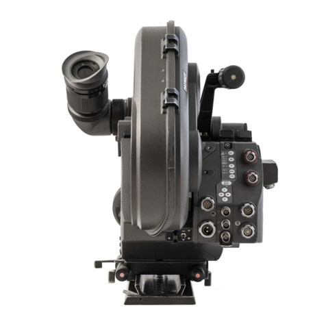
ARRI IVS User manual

IVS
Instruction Manual
Integrated Video Assist System for the ARRIFLEX 535B
As of: February 2004
ALL ARTWORK, PICTURES AND TEXTS ARE COVERED BY OUR COPY-RIGHT.
THEY MUST NOT BE COPIED FOR REPRODUCTION (E.G. ON CD-ROM DISKS OR INTERNET-SITES) OR USED IN THEIR ENTIRE FORM OR IN EXCERPTS WITHOUT OUR PREVIOUS WRITTEN AGREEMENT.
IFYOU ARE DOWNLOADING PDF-FILES FROM OUR INTERNET HOME-PAGE FOR YOUR PERSONAL USE, MAKE SURE TO CHECK FOR UPDATED VERSIONS.
WECANNOT TAKE ANY LIABILITY WHATSOEVER FOR DOWNLOADED FILES, AS TECHNICAL DATA ARE SUBJECT TO CHANGE WITHOUT NOTICE.

Genlock in
Data in
IVS Off / On / keyboard locked
Mini Monitor connector
(“normal video” or “video with data”)
”Normal video” composite out or Y-out
(“normal video” or “video with data”)
“Video with data” composite out or C-out
(“normal video” or “video with data”)
Adjustment wheel for iris IVS lens
RS connector

3
Contents
1Contents
1Contents .........................................................3
2. Safety Instructions and Legal Disclaimer ......5
2.1. Safety Instructions.......................................5
2.2 Disclaimer .................................................8
3General Description of the IVS ................11
3.1 Main Features ..........................................11
3.2 System Components .................................13
4Setup ............................................................17
4.1 Inserting the Optic ....................................17
4.2 Mounting the IVS on the camera ...............19
5Standard Video Controls ..........................35
5.1 Off/ On and Locking the Keyboard ...........35
5.2 Mechanical Iris ........................................36
5.3 Aligning the Image and Focusing ..............37
5.4 White Balance (WB) .................................39
5.5 Gain Control ...........................................40
5.6 Frame Store and Compare........................41
5.7 Switching between Composite Video and Y/C .42
5.8 Flicker free on/off ....................................43
6Inserter Facilities ........................................45
6.1 Setting the On Screen Displays..................46
6.2 Main Menu..............................................48
6.3 Format Markings Menu ............................49
6.4 Status Menu.............................................55
6.5 Time Code Menu......................................65
6.6 USER BITS Menu ......................................71
6.7 Text Menu ................................................75
6.8 Pull-Down Menu.......................................79
6.9 Display Menu ..........................................85
6.10 VITC Line Menu........................................91
6.11 White Line Menu ......................................95
7Technical Data ..........................................100
8Order Numbers ........................................100
9Index ..........................................................101
ARRI Service......................................................111

4
MGC
MGC
ENTER
INSERT
MODE
STO
FR
WB
MGC
MM
ONON
ATW
ON
STO
CMP
COMPOSITE
Y/C
Mode (Framestore / Compare)
Go to sub menu or
move position of inserted windows left or
reduce inserter values or
move IVS film counter active digit left
Go to sub menu or
move position of inserted windows right or
increase inserter values or
move IVS film counter acitve digit right
Increase gain or
cursor up or
move inserted windows up or
increase value IVS film counter active digit White Balance
(Indoor / Outdoor / Automatic)
Manual Gain Control (ON)
Flickerfree (ON)
Reduce gain or
cursor down or
move inserted window down or
reduce value IVS film counter active digit
Activate inserter onscreen menu or
store position of inserted window or
store IVS film counter value
Store Key
Composite video or Y/C video
"Normal video" or
"video with data" at mini monitor output
"Normal video" or
"video with data" at Y/C output
Contents

5
2. Safety Instructions and Legal Disclaimer
2.1. Safety Instructions
Please always follow these instructions to help
ensure against injury to yourself and damage
to the system or other objects.
This safety information is additional to the
product-specific operating instructions in
general and must be strictly observed for safety
reasons. They are no substitute to settled down
you own safety measures.
Warning signs
Possible risk of injury or damage to equipment.
This symbol indicates the risk of electric shock
or fire danger that could result in injury or
equipment damage.
General safety instructions
Read and understand all safety and operating
instructions before you operate or install the system.
Retain all safety and operating instructions for
future reference.
Heed all warnings on the system and in the
safety and operating instructions before you
operate or install the system. Follow all installation
and operating instructions.
Do not use accessories or attachments not
recommended by ARRI, as they may cause
hazards and void the warranty.
Do not repair any part of the system. Repairs
must only be carried out by authorized ARRI
repair shops.
Do not remove any safety measure of the system.
Safety Instructions

6
Do not operate the system in high humidity
areas or expose it to water or moisture.
Do not place the system on an unstable cart,
stand, tripod, bracket, or table. The system may
fall, causing serious personal injury and
damage to the system or other objects.
Operate the system using only the type of power
source indicated in the manual. Unplug the power
cord by gripping the power plug, not the cord.
Never insert objects of any kind into the any part
of the system through openings, as the objects may
touch dangerous voltage points or short out
parts. This could cause fire or electrical shock.
Unplug the system from the power outlet before
opening any part of the system or before
making any changes on the systems, especially
the attaching or removing of cables.
Do not use solvents to clean.
Do not remove any screws which are secured
with paint!
Clean optical surfaces only with a lens brush or
a clean lens cloth! In cases of solid dirt moisten
a lens cloth with pure alcohol.
Specific safety instructions
Attention! Danger of injury!
Never place your hand in the lens mount
receptacle or the inside of the camera or
magazine while it is running.
The control panel of the IVS must not be operated
using hard ord sharp-edged tools, e.g. screw-
drivers.
•In order to ensure optimal performance, it is essential
that you acquaint yourself with this instruction manual,
and the manual of the ARRIFLEX 535B.
•Use the IVS 535B only with ARRIFLEX 535B cameras,
and only as described in this manual!
•Assembly and initial operation should only be carried
out by persons who are familiar with the equipment!
Safety Instructions

7
• The video lens must be properly inserted into the CCD
optic module, as incomplete insertion might result in
damage to the beam splitter when attaching the unit to
the camera body!
•Check all operations on the corresponding monitor!
Any violation of this safety instructions or the non-observance
of personal care could cause serious injuries (including
death) and damages on the system or other objects.
Product Specifications
In the case of inquiries or when ordering parts, please
advise serial number and model.
•Always send the CCD optic module together with the
inserter/antiflicker module in case of any service jobs.
Explanation of the Symbols
in the Instruction Manual
§indicates objects which are shown in photo-
graphs or drawings.
All menus are shown in the respective typeface: MENU
Operating keys are represented in capitalized letters: STO
Safety Instructions

8
2.2 Disclaimer
No part of this document may be copied or reproduced in
any form or by any means without prior written consent of
ARRI. ARRI assumes no responsibility for any errors that
may appear in this document. The information is subject
to change without notice. For actual design-in, refer to the
latest publications of ARRI data sheets or data books, etc.,
for the most up-to-date specifications. Not all products
and/or types are available in every country. Please check
with an ARRI sales representative for availability and
additional information.
While ARRI endeavors to enhance the quality, reliability and
safety of their products, customers agree and acknowledge
that the possibility of defects thereof cannot be eliminated
entirely. To minimize risks of damage to property or injury
(including death) to persons arising from defects in the
products, customers must incorporate sufficient safety
measures in their work with the system and have to heed
the statuted canonic use.
The ARRI IVS is only available for commercial customers.
The customer grants by utilization, that the ARRI IVS or
other components of the system are only deployed for
commercial use. Otherwise the customer has the obligation
to contact ARRI preceding the utilization.
ARRI or its subsidiaries does not assume any liability for
infringement of patents, copyrights or other intellectual
property rights of third parties by or arising from the use
of ARRI products or any other liability arising from the
use of such products. No license, express, implied or
otherwise, is granted under any patents, copyrights or
other intellectual property rights of ARRI or others.
ARRI or its subsidiaries expressly excludes any liability,
warranty, demand or other obligation for any claim,
representation, or cause, or action, or whatsoever,
express or implied, whether in contract or tort, including
negligence, or incorporated in terms and conditions,
whether by statue, law or otherwise. In no event shall
ARRI or its subsidiaries be liable for or you have a remedy
for recovery of any special, direct, indirect, incidental, or
consequential damages, including but not limited to lost
profits, lost savings, lost revenues or economic loss of any
Disclaimer

9
kind or for any claim by third party, downtime, good-will,
damage to or replacement of equipment or property, any
costs or recovering of any material or goods associated
with the assembly or use of our products, or any other
damages or injury of persons and so on or under any
other legal theory.
In the case one or all of the forgoing clauses are not
allowed by applicable law, the fullest extent permissible
clauses by applicable law are validated.
ARRI is a registered trademark of Arnold & Richter Cine
Technik GmbH & Co Betriebs KG.
Disclaimer
10

11
3General Description of the IVS
The Integrated Video-Assist System (IVS) for the ARRIFLEX
535B ergonomically integrates with a minimum of external
cabling a complete video assist system into the camera body.
It offers unsurpassed image quality combined with a state-of-
the-art inserter to add frame lines, time code, camera status
and text into the video image.
3.1 Main Features
•Integrated into the camera body:
Instead of a bulky add on, the video assist is an integral
part of the camera.
•High sensitivity:
A high speed lens with an aperture of 1: 1.4 and one of
the most sensitive CCD-chips available on the market
provide an excellent color video image in editing quality
even when the light is set for high speed film stock to
be pushed during processing.
•High resolution:
The design of the new IVS optics was based on the
535B’s viewfinder data and resulted in an image quality
which can not be attained by add-on solutions.
•Flicker-free:
An integrated digital frame store enables the video
camera to be synchronized to the film camera’s mirror
shutter and provides a flicker-free video image from
5-60 fps. The recording of the video image is synchro-
nized with the ideal position of the mirror shutter.
•Integrated frame line inserter:
Frame lines can be electronically added to the video
image. This ensures that the lines are visible even in
low contrast conditions. The area outside the frame
lines can be darkened electronically to emphasize the
important image area.
•Integrated IVS film counter:
In addition to the camera speed an independent IVS film
counter can be inserted into the camera status line to
support material logging.
General Description

12
•Integrated time code inserter:
It is possible to insert time code into the video image.
Thus, the video assist creates a reliable link to video
editing. The information on “3:2” pull-down, which
can be inserted as well, ensures the same reliability in
an NTSC environment.
•Integrated text inserter:
Additional text like take numbers or production names
can be added to the video image by sending characters
via a serial interface.
•Additional Y/C Outputs:
In addition to the usual composite output, the IVS
offers a Y/C output (S-VHS) for an even better video
image without annoying color artifacts, with or without
data inserted into the video image.
•On-Screen programming:
All functions which do not effect the image appearance
directly, such as gain control, can be conveniently pro-
grammed with an onscreen menu on the video monitor.
•Image compare function:
It is possible to store a particular image and compare
it against other images. This clearly shows the difference
between the images, e.g. during stop effect shots.
•Automatic and manual gain control:
The gain is controlled automatically to its best value
but can also be set manually.
•External synchronization input (Genlock):
The IVS has an external synchronization input to
enable multiple camera use.
•Indoor/Outdoor and automatic white balance:
White balance can be set to indoor with 3200 K,
outdoor with 5600 K and automatic adjustment.
•Mini monitor connector:
The IVS offers a connector for a 12 V LCD mini monitor.
Note: If neither time code is used nor data is sent via
the serial interface, it is possible to work without
the data cable ZV4.
Note: As the IVS is designed for an 80 : 20 beam splitter,
there is no need for the 50 : 50 beam splitter,
which is used for other color video assists.
General Description

13
3.2 System Components
The IVS consists of:
•Optic Silent and/or ............................ (K2.47298.0)
•Optic Academy ................................. (K2.47301.0)
•Video Electronic complete ......... (K2.47306.0 for PAL
or K2.47307.0 for NTSC)
The complete video electronic consists of four parts:
•CCD Optic Module
•Inserter/Antiflicker module
•RS cable............................................ (K4.47733.0)
•Data cable ZV4 ................................. (K4.47730.0)
3.2.1 Optic Silent
For a complete and working IVS, either the optic silent or
the optic academy has to be installed inside the CCD optic
module. These are easily interchangeable.
The optic silent forms an image on the CCD chip which is
based on the 35 mm silent format with a picture width of
24 mm. To check for important objects outside the image
recorded on film there is an additional area around the
format markings.
The lenses are especially designed and built for use with the
ARRIFLEX 535B to achieve the best image quality possible.
The aperture of 1:1.4 is particularly important for use as
video assist lenses: only a small portion of the light that passes
through the camera lens goes to the video chip. The lenses
are not designed as zoom lenses because it would be im-
possible to get the same image quality and speed.
All silent optics are marked with an S in the serial number,
e.g. S0040.
There is no difference between lenses for PAL and NTSC.
General Description

14
3.2.2 Optic Academy
For a complete and working IVS, either the optic silent or
the optic acacemy has to be installed inside the CCD optic
module. They are easily interchangeable.
The optic academy forms an image on the CCD chip based
on the 35mm academy format with a picture width of 22mm.
To check for important objects outside the image recorded
on film there is an additional area around the format markings.
The lenses are especially designed and built for the use with
the ARRIFLEX 535B to achieve the best image quality possible.
The aperture of 1:1.4 is particularly important for use as
video assist lenses: only a small portion of the light passes
goes through the camera lens goes to the video chip. The
lenses are not designed as zoom lenses because it would
be impossible to get the same image quality and speed.
All academy optics are marked with an N in the serial number,
e.g. N0040.
There is no difference between lenses for PAL and NTSC.
3.2.3 CCD Optic Module
The CCD optic module, which is mounted on the ARRI-
FLEX 535B’s viewfinder system, has to be equipped with
a video lens. This module contains the CCD chip and all
the necessary elements to center the video image on the
TV-monitor screen and to adjust focus. It also houses a
video pre-amplifier to increase the sensitivity of the IVS at
low light conditions.
The CCD optic module is available in two versions for PAL
or NTSC.
Note: It is necessary to keep the combination of CCD
optic module and inserter/antiflicker module
together as delivered. Mixing the modules might
lead to reduced image quality.
General Description

15
3.2.4 Inserter/Antiflicker Module
The compact inserter/antiflicker module, which is mounted
on top of the ARRIFLEX 535B’s electronic cover, holds the
video camera electronic, an anti flicker processor and the
entire inserter. All electronic control elements, as well as
all in- and outputs are located here.
The inserter/antiflicker module is available in two versions
for PAL or NTSC.
Note: It is necessary to keep the combination of CCD
optic module and inserter/antiflicker module
together as delivered. Mixing the modules might
lead to reduced image quality.
3.2.5 RS cable
The RS cable supplies the IVS with power and information
regarding the camera speed and shutter mirror position.
It plugs into the ARRIFLEX 535B RS connector and the
inserter/antiflicker module. Please observe the color coding.
3.2.6 Data cable ZV4
Note: Sending data to the film camera through the
IVS is only possible when the IVS is switched on.
The data cable ZV4 is necessary to send additional
information such as time code and RS 232 data to the
IVS. This cable is necessary if time code is in use or if
accessories such as the Laptop Camera Controller need
access to the data interface of the IVS and the camera.
If neither time code is used nor data is sent via the serial
interface, it is possible to work without the data cable ZV4.
General Description

16

17
F
S1 S4
S2
S3
4Setup
4.1 Inserting the Optic
For a complete and working IVS, either the optic silent or
the optic academy must be installed inside the CCD optic
module.
A 1.5 mm allen key is used.
Do not touch optical surfaces.
All lenses must be clean.
Do not use force.
•Turn the protecting cap at the end of the CCD optic
module §counter clockwise and remove it to
access the lens receptacle.
•Remove the cover on the front side of the CCD optic
module §by turning it counter-clockwise to
access the alignment screw.
•Make sure that the focus screw (S3) §and the
alignment screws (S1, S2 and S4) §are in the
middle of their range.
protecting cap
cover
Setup

18
•Insert the video lens with the thread first into the CCD
optic module as far as it will go §.
•Turn the lens left or right to insert the iris key into its
path and push the lens further in. Close the thread
clockwise until the lens is secured.
The video lens must be properly inserted into
the lens mount until the end of the thread.
Uncomplete insertion might result in damage to
the beam splitter when attaching the unit to the
camera body.
•Re-attach the cover and protecting cap on the CCD
optic module.
•To release the lens again, rotate carefully counter-
clockwise until loose and pull forwards to remove.
optic
Setup

19
4.2 Mounting the IVS on the camera
The following tools are needed to mount the IVS:
– 1.2 x 8 mm screwdriver or coin.
If the beam splitter is to be changed:
–Phillips screwdriver size 0
–Phillips screwdriver size 1
–1.5 mm allen key
–Straight pair of tweezers.
Disconnect camera from all power supplies.
Do not use force
Ensure clean contacts.
The CCD optic module is mounted on the viewfinder of
the ARRIFLEX 535B, the inserter/antiflicker module is
placed on top of the electronic cover.
•Be sure to use a 80 : 20 beam splitter instead an 50 : 50
beam splitter. Change if necessary.
Note: Because of the high speed video optic (Academy
or Silent), it is no longer necessary to use a 50: 50
beam splitter, as it was with other color video assists.
The IVS is designed to work with an 80 : 20
beam splitter.
Support the viewfinder system.
Do not touch optical surfaces.
Setup

20
4.2.1 Changing the Beam Splitter
Note: This is not necessary if a 80 : 20 beam splitter
is already installed.
Because of the high speed video optic (Academy
or Silent), it is no longer necessary to use a 50:50
beam splitter, as it was with other color video assists.
The IVS is designed to work with an 80:20
beam splitter.
•Press the release key §and take the viewfinder
system off the camera.
•Open the 7 mounting screws §.
•Open the 3 mounting screws §.
The viewfinder top is connected with two cables
to the rest of the units.
Do not use force in separating the units.
•Lift the top side of the viewfinder carefully off to get
access to the beam splitter and mounting ring assembly.
release-key
7 mounting screws
3 mounting screws
Setup
Other manuals for IVS
1
Table of contents
Other ARRI Camera Accessories manuals

ARRI
ARRI MAXIMA QL User manual

ARRI
ARRI cforce mini RF User manual

ARRI
ARRI ARRIHEAD II User manual

ARRI
ARRI SRH-3 User manual

ARRI
ARRI SRH-3 Operating instructions

ARRI
ARRI Mattebox MB-20 User manual

ARRI
ARRI ALEXA Mini LF SUP 7.1.2 How to use

ARRI
ARRI WCU-4 User manual

ARRI
ARRI 535B User manual

ARRI
ARRI ALEXA User manual