manuals.online logo
Brands
  1. Home
  2. •
  3. Brands
  4. •
  5. ASCO Valves
  6. •
  7. Control Unit
  8. •
  9. ASCO Valves 327C Series Installation and operating instructions

ASCO Valves 327C Series Installation and operating instructions

ASCO Valves® All Rights Reserved. I&M V_10004_AA
E327865 - 06/2023 www.emerson.com/ASCO Page 1 of 4
To reduce the risk of death, serious
injury, or property damage:
• Personnel installing, maintaining, or operating this
equipment must be qualied and follow these
instructions. See also separate solenoid installation &
maintenance instructions. Keep this document.
• Before installing or maintaining the valve, turn o󰀨
electrical power, depressurize valve, extinguish all
open ames and avoid any type of sparking or ignition.
Vent hazardous or combustible uid to a safe area.
DESCRIPTION
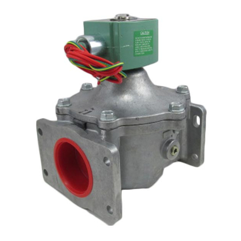
Series 327C valves are 3-way, 2-position (3/2) solenoid valves designed
for general service. Valves are made of stainless steel. Series 327C valves
are provided with an explosionproof/watertight solenoid.
North American Hazardous Location Approvals (UL, ULC-Division) (If
marked on nameplate)
• Explosionproof Class I, Division 1, Groups B, C, D, T*Tamb*
• Explosionproof Class II, Division 1, Groups E, F, G, T*Tamb*
• Enclosure meets Type 4X – Watertight, Types 6 and 6P Submersible
Canadian Zone Approvals (If marked on nameplate)
Class I, Zone 1, Group IIB+H2
Class II, Zone 21, Group IIIC
European Approvals (ATEX, IECEx) (If marked on nameplate)
• Ingress Protection IP66, 68
II2 G Ex db IIC Gb, T*Tamb*
II2 D Ex tb IIIC Db, T*Tamb*
*See T code table
IECEx ATEX
IEC 60079-0:2017 EN IEC 60079-0:2018 / AC: 2020
IEC 60079-1:2014 EN 60079-1:2014
IEC 60079-31:2013 EN 60079-31:2014

IMPORTANT: Ex db and tb solenoids can be installed in hazardous
areas zone 1 and zone 2.
Zone 0: Explosive gas-air mixture continuously present or present for
longer periods.
Zone 1: Explosive gas-air mixture likely to occur in normal operation.
Zone 2: Explosive gas-air mixture not likely to occur and if it occurs, it
will exist only for a short time.
OPERATION
To reduce the risk of ignition of hazardous
atmospheres, disconnect the equipment from the supply
circuit before opening. Keep assembly tightly closed when in
operation.
Normally Closed: Applies pressure when solenoid is energized.
Solenoid De-energized: Flow is from Port 2 to Port 1. Port 3 is closed.
Solenoid Energized: Flow is from Port 3 to Port 2. Port 1 is closed.
Normally Open: Applies pressure when solenoid is de-energized.
Solenoid De-energized: Flow is from Port 1 to Port 2. Port 3 is closed.
Solenoid Energized: Flow is from Port 2 to Port 3. Port 1 is closed.
Universal

Pressure can be applied at any port.
OPERATION OF MANUAL OPERATORS (OPTIONAL)
Manual Operator – Push Type
This is a momentary manual operator. When the button is fully depressed,


port 2 to port 1, without electrically energizing the valve. When the button
is released, the core spring will automatically return the valve to its de-
energized position.
Manual Operator – Screw Type
This is a manually sustained operator. The button must be pushed and
then turned clockwise to operate. This action will lift the lower seat seal


the button is released, the valve will stay in position. To disengage the
operator, turn the button anti-clockwise until the operator disengages, and
the core spring is able to fully return the valve to its de-energized position.
Flow Diagrams
OPERATION DE-ENERGIZED ENERGIZED
NORMALLY
CLOSED
PRESSURE
AT 3
NORMALLY
OPEN
PRESSURE
AT 1
UNIVERSAL
PRESSURE
AT ANY PORT
INSTALLATION
Check nameplate for correct catalog number, pressure, voltage, frequency,



the valve. Contact ASCO or your supplier for more information about
this valve or other valve options if this valve is not suitable for your
application.
NOTE: Process-wetted single seal materials per UL122701 are chemically

hydraulic oil.
Future Service Considerations
Provision should be made for performing seat leakage, external leakage,
and operational tests on the valve with a nonhazardous, noncombustible

Temperature Limitations

Check nameplate for maximum pressure rating.
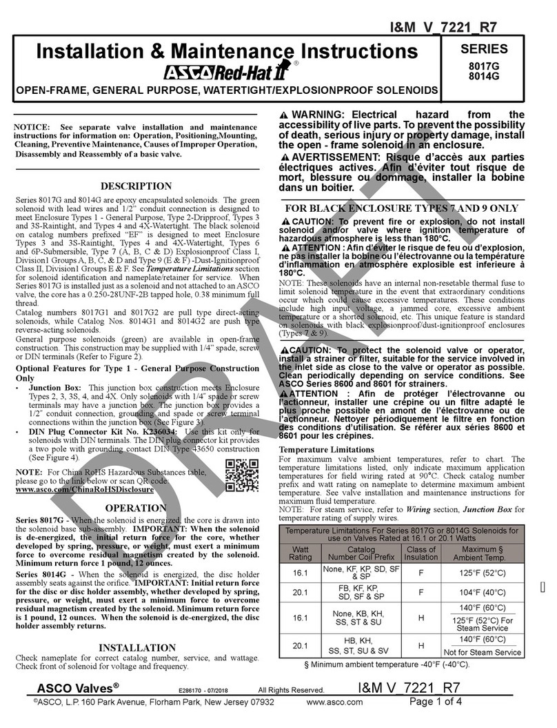
Installation & Maintenance Instructions
3-WAY, 2-POSITION DIRECT-ACTING SOLENOID VALVES
NORMALLY CLOSED, NORMALLY OPEN OR UNIVERSAL OPERATION
1/4” NPT, RC 1/4”, G 1/4” - 9.5MM ORIFICE - STAINLESS STEEL CONSTRUCTION
SERIES
327C
To reduce the risk of death, serious
injury, or property damage:
• Personnel installing, maintaining, or operating
this equipment must be qualied and follow these
instructions. See also separate solenoid installation &
maintenance instructions. Keep this document.
• Before installing or maintaining the valve, turn o󰀨
electrical power, depressurize valve, extinguish all open
ames and avoid any type of sparking or ignition. Vent
hazardous or combustible uid to a safe area.
Pour réduire les risques de
décès, de blessures graves ou de dommages matériels:
• Le personnel qui installe, entretient ou exploite cet
équipement doit être qualié et suivre les instructions
qui s’y rapportent. On suivra aussi les instructions
d’installation et de maintenance de la bobine délivrées
séparément. Gardez ce document.
• Avant d’installer ou d’intervenir sur la vanne, couper
le courant, dépressuriser la vanne, éteindre toutes les
ammes nues et éviter tout type d’étincelle ou d’ignition.
Évacuer les liquides dangereux ou combustibles vers
un endroit sûr.
WARNING
ADVERTISSEMENT
I&M V_6584_VB
SERIES
8003G/H
8007G/H
8202G/H
Installation & Maintenance Instructions
ASCO RED-HAT II OPEN-FRAME, GENERAL PURPOSE, WATERTIGHT/EXPLOSION
PROOF SOLENOIDS OPTIONAL FEATURE FOR OPEN FRAME (GENERAL PURPOSE)
CONSTRUCTION ONLY
ASCO Valves® E303145 - 03/2020 All Rights Reserved. I&M V_6584_VB
©ASCO, L.P. 160 Park Avenue, Florham Park, New Jersey 07932 www.emerson.com Page 1 of 7
— SERVICE NOTICE —
ASCO®solenoid valves with design change letter “G” or “H”
in the catalog number (ex. 8210G1) have an epoxy encapsulated
ASCO™Red Hat II™solenoid. This solenoid replaces some of
the solenoids with metal enclosures and open-frame constructions.
Follow these installation and maintenance instructions if your
valve or operator uses this solenoid.
See separate instructions for basic valve.
DESCRIPTION
Catalog numbers 8003G/H, 8007G/H and 8202G/H and are epoxy
encapsulated pull-type solenoids. The green solenoid with lead wires
and 1/2 conduit connection is designed to meet Enclosure Type
1-General Purpose, Type 2-Dripproof, Types 3 and 3S-Raintight,
and Types 4 and 4X-Watertight. The black solenoid on catalog
numbers prexed “EF” or “EV” is designed to meet Enclosure
Types 3 and 3S-Raintight, Types 4 and 4X-Watertight, Types 6
and 6P-Submersible, Type 7, Explosionproof Class I, Division1
Groups A, B, C, & D and Type 9, -Dust-Ignitionproof Class II,
Division1 Groups E, F & G. The Class II, Groups F & G Dust
Locations designation is not applicable for solenoids or solenoid
valves used for steam service or when a class “H” solenoid is used.
See Temperature Limitations section for solenoid identication and
nameplate/retainer for service. When installed just as a solenoid and
not attached to an ASCO valve, the core has a 0.250-28 UNF-2B
tapped hole, 0.38 or 0.63 minimum full thread.
NOTE: Catalog number prex “EV” denotes stainless steel
construction.
Solenoid catalog numbers 8202G/H1, 8202G/H3, 8202G/H5
and 8202G/H7 are epoxy encapsulated push-type, reverse-acting
solenoids having the same enclosure types as previously stated for
Catalog numbers 8003G/H1 and 8003G/H2. 8007G/H are 3-way
solenoid operators with a pipe port or adapter, exhaust protector or
vent at the top of the solenoid base sub-assembly.
Series 8003G/H, 8007G/H and 8202G/H solenoids are also
available in:
• Open-Frame Construction: The green solenoid may be
supplied with 1/4˝ spade, screw or DIN terminals. (Refer to
Figure 4)
□ DINPlugConnectorKitNo.K236034:Use this kit only
for solenoids with DIN terminals. The DIN plug connector
kit provides a two pole with grounding contact DIN Type
43650 construction (See Figure 6).
• Panel Mounted Construction: These solenoids are specically
designed to be panel mounted by the customer. Refer to Figures
specied in this I&M and the section on Installation of Panel
Mounted Solenoid for details.
• Junction Box: This junction box construction meets Enclosure
Types 2, 3, 3S, 4, and 4X. Only solenoids with 1/4˝ spade or
screw terminals may have a junction box. The junction box
provides a 1/2˝ conduit connection, grounding and spade or
screw terminal connections within the junction box (See
Figure 5).
• Multipin Connectors: All Multipin connectors (VT, VB, ZT,
ZB) do not have any enclosure ratings.
NOTE: For China RoHS Hazardous Substances
table, please go to the link below or scan QR code:
www.asco.com/ChinaRoHSDisclosure
SOLENOID CHARACTERISTICS
Series 8003G/H and 8007G/H - When the solenoid is energized,
the core is drawn into the solenoid base sub-assembly.
IMPORTANT:Whenthe solenoidisde-energized,theinitial
returnforceforthecore,whetherdevelopedbyspring,pressure,
orweight,mustexertaminimumforcetoovercomeresidual
magnetismcreatedbythesolenoid.Minimumreturnforcefor
ACconstructionis11ounces,and5ouncesforDCconstruction.
Series 8202G/H - When the solenoid is energized, the disc holder
assembly seats against the orice. When the solenoid is de-
energized , the disc holder assembly returns.
IMPORTANT:Initialreturnforceforthediscordischolder
assembly,whetherdevelopedbyspring,pressure,orweight,must
exertaminimumforcetoovercomeresidualmagnetismcreated
bythesolenoid.Minimumreturnforceis1pound,5ounces.
Approved minimum uid and ambient temperature is -76 °F (-60 °C) for the operator.
Actual temperature can be limited depending on valve limits.
Temperature Limitations
For maximum solenoid ambient temperatures, refer to chart. The
temperature limitations listed, only indicate maximum application
temperatures for eld wiring rated at 90 °C. Check catalog number
prex and watt rating on nameplate to determine maximum
ambient temperature. See valve installation and maintenance
instructions for valve temperature limitations.
NOTE: For steam service, refer to Wiring section, Junction Box
for temperature rating of supply wires.
Temperature Limitations For Series 8003G, 8007G or 8202G
Watt
Rating
Catalog
Number Coil Prex Class of
Insulation
Maximum Ambient/
Fluid Temperature
10.1 &
17.1 NONE, EF, EV, KF, KP, SC, SD,
SF, SP, VT, VB, ZT & ZB F 125 °F (52 °C)
10.1,
17.1 &
24.6
(EV/EF)HB, (EV/EF)HT, KB,
KH, KC, SS, ST, SW, SU, (EV/
EF)HC H 140 °F (60 °C)
11.6 &
22.6 NONE, EF, EV, KF, KP, SC, SD,
SF, SP, VT, VB, ZT & ZB F 104 °F (40 °C)
11.6 &
22.6 (EV/EF)HB, (EV/EF)HT, KB,
KH, SS, ST, SU, SV H 104 °F (40 °C)
15.6 NONE, KB, SS, SV H 104 °F (40 °C)
12.0 NONE, EF, EV, KF, SC, SF,
VT, ZT F 131 °F (55 °C)
Page 2 of 7 I&M V_6584_VB
©ASCO, L.P. 160 Park Avenue, Florham Park, New Jersey 07932 www.emerson.com
¹ = EF, EV data applies to Explosionproof coils only.
² = Some DC solenoid valves can be operated at maximum ambient
temperature of 55 °C / 131 °F with reduced pressure ratings. See
valve I&M for maximum operating pressure di󰀨erential ratings.
³ = Steam Service Valves have a maximum ambient temperature of 55 ° C
/ 131 °F.
Positioning
This solenoid is designed to perform properly when mounted in
any position. However, for optimum life and performance, the
solenoid should be mounted vertically and upright to reduce the
possibility of foreign matter accumulating in the solenoid base
sub-assembly area.
Wiring
To reduce the risk of electrocution,
re, or property damage, wiring must comply with local
codes and the National Electrical Code.
Pour réduire les risques
d’électrocution, d’incendie ou de dommages matériels,
le câblage doit être conforme aux codes locaux et au
NEC.
All solenoids supplied with lead wires are provided with a
grounding wire which is green or green with yellow stripes and
a 1/2˝ conduit connection. To facilitate wiring, the solenoid may
be rotated 360°. For explosionproof solenoid version, the conduit
lead wires are factory sealed for use in hazardous locations. On
some solenoids, a grounding wire (green or green with yellow
stripes) is provided.
WARNING The solenoid must be grounded with
grounding wire (if included) or rigid metallic conduit -
do not rely on pipe as ground.
ADVERTISSEMENT La bobine doit être mise à la
terre avec un l de terre (le cas échéant) ou via un conduit
métallique rigide – n’utilisez pas la tuyauterie comme
masse.
CAUTION Cryogenic Applications - Solenoid lead
wire insulation should not be subjected to cryogenic
temperatures. Adequate lead wire protection and routing
must be provided.
ATTENTION Application cryogénique. Les câbles
électriques ne doivent pas être soumis à des températures
cryogéniques. Une protection adequate des cables
électriques doit être fournie.
WARNING
ADVERTISSEMENT
Temperature Limitations for Series 8003H, 8007H and 8202H
Solenoids
Watt Ratings Maximum Ambient/
Fluid Temperature
Prex ¹ Coil
Class
AC DC
60 Hz 50 Hz °C °F
EF, EV FT 10.1 10.1 - 52 125
EF, EV FB 17.1 17.1 -
FT 10.1 10.1 - 55 131
FB 17.1 17.1 -
HT - - 11.6
40 ² 104 ²
HF - - 15.6
HB - - 22.6
EF, EV HT - - 11.6
EF, EV HF - - 15.6
EF, EV HB - - 22.6
HT 10.1 10.1 -
60 ³ 140 ³
HB 17.1 17.1 -
EF, EV HT 10.1 10.1 -
EF, EV HB 17.1 17.1 -
EF, EV HC - - 24.6
INSTALLATION
ProductVerication
Check nameplate for correct catalog number, service, and wattage.
Check front of solenoid for voltage and frequency. Never apply
incompatible uids or exceed pressure rating of the valve. Contact
ASCO or your supplier for more information about this valve or
other valve options if this valve is not suitable for your application.
Strainerorlterrequirement
To protect the solenoid valve, install a strainer or lter, suitable
for the service involved, in the inlet side as close to the valve as
possible. Clean periodically depending on service conditions.
WARNING Electrical hazard from the accessibility
of live parts. To prevent the possibility of death, serious
injury or property damage, install the open - frame
solenoid in an enclosure.
ADVERTISSEMENT Risque d’accès aux parties
électriques actives. An d’éviter tout risque de mort,
blessure ou dommage, installer la bobine dans un boitier.
FORBLACKENCLOSURETYPES7AND9ONLY
CAUTION To prevent re or explosion, do not
install solenoid and/or valve where ignition temperature of
hazardous atmosphere is less than 165 °C. On valves used
for steam service or when a class “H” solenoid is used, do not
install in hazardous atmosphere where ignition temperature
is less than 180 °C. See nameplate/retainer for service.
ATTENTION An d’éviter le risque de feu ou
d’explosion, ne pas installer la bobine ou l’électrovanne
ou la température d’inammation en atmosphère
explosible est inferieure à 165 °C. Pour les vannes
vapeur ou lorsqu’une bobine de classe H est utilisée,
ne pas installer en atmosphère explosible lorsque la
température d’inammation est inférieure à 180 °C.
Consulter les conditions d’utilisations sures indiquées
sur le produit ou dans la notice.
NOTE: These solenoids have an internal non-resetable thermal
fuse to limit solenoid temperature in the event that extraordinary
conditions occur which could cause excessive temperatures. These
conditions include high input voltage, a jammed core, excessive
ambient temperature or a shorted solenoid, etc. This unique feature
is a standard feature only in solenoids with black explosionproof/
dust-ignitionproof enclosures (Types 7 & 9).
CAUTION To protect the solenoid valve or
operator, install a strainer or lter, suitable for the
service involved in the inlet side as close to the valve
or operator as possible. Clean periodically depending
on service conditions. See ASCO Series 8600 and
8601 for strainers.
ATTENTION An de protéger l’électrovanne ou
l’actionneur, installer une crépine ou un ltre adapté
le plus proche possible en amont de l’électrovanne
ou de l’actionneur. Nettoyer périodiquement le ltre
en fonction des conditions d’utilisation. Se référer aux
séries 8600 et 8601 pour les crépines.
(For 12.0-Watt construction only): These
solenoids are provided with a special coil containing
solid state components that can be damaged by transient
voltages, over voltage, high temperatures or improper
valve assembly.
(Construction 12.0 watts uniquement):
ces électrovannes sont fournies avec une bobine spéciale
contenant des composants semi-conducteurs qui peuvent
être endommagés par des tensions transitoires, des
surtensions, des températures élevées ou un assemblage
inapproprié de la vanne.
1. When establishing the valve’s electrical connections, the
circuit that it is being connected to needs to have the proper
SPD (Surge Protective Device) installed. This is to limit
the eects of over voltages and impulse currents caused by
lightning and switching surges occurring on the power lines.
Failure to provide this conditioning on the aected circuits can
lead to either open circuiting or short circuiting of the solenoid
valve coil. Information on the proper sizing of SPDs and
installation requirements can be found in numerous industry
standards such as IEC 61643---12, IEEE STD. C62.23, IEEE
CAUTION
ATTENTION
I&M V_10004_AA
Page 2 of 4 I&M V_10004_AA
www.emerson.com/ASCO
Positioning
This valve is designed to perform properly when mounted in any position.
However, for optimum life and performance, the solenoid should be
mounted vertically and upright to reduce the possibility of foreign matter
accumulating in the solenoid base sub-assembly area.
Mounting
For mounting dimensions, refer to Figure 1.
Piping
Connect piping to valve according to markings on valve body. Apply pipe
compound sparingly to male pipe threads only. If applied to valve threads,

pipe strain and valve damage by properly supporting and aligning piping.
When tightening the pipe, do not use valve or solenoid as a lever. Locate
wrenches applied to valve body or piping as close as possible to connection
point. To avoid damage to the valve body, DO NOT OVERTIGHTEN
PIPE CONNECTIONS. If PTFE tape, paste, spray, or similar lubricant is
used, use extra care when tightening due to reduced friction.
Temporary Connector
The Temporary Connector, if equipped, is an optional part designed to
reduce the time to test multiple valves. The connector has a standard C6
female connection (IEC 60320-3 standard) and is prewired to the coil so
there is no need to remove the enclosure cover to test valve function. The
valve can be tested by connecting a male C5 connector to the Temporary
Connector. Then, apply the required voltage listed on the Nameplate to
actuate the valve for test.
To prevent the possibility of death, serious
injury or property damage, the optional Temporary Connector,
if applicable (see Figure 1), must be removed before nal
installation. The Temporary Connector is for testing purposes
only and not intended for nal use.
These solenoid valves are intended for use on
clean dry air or inert gas as well as, water or light oil (<65CSt).
The media should be ltered to 50 micrometer or better. The
dew point of the media should be at least 10°C (18°F) below the
minimum temperature to which the media could be exposed,
to prevent freezing. If lubricated air is used, the lubricant must
be compatible with the used elastomers. Instrument air in
compliance with ANSI/ISA Standard S7.3 (1975) exceeds the
above requirements and is therefore, an acceptable media
for these valves. The exhaust port can also be optionally
protected either by means of a lter or with the help of a pipe
connection to a central lter system.
MAINTENANCE
To prevent the possibility of death,
serious injury, or property damage, turn o󰀨 electrical power,
depressurize valve, and vent uid to a safe area. Delay opening
enclosure for 35 minutes before servicing the valve. Solenoid
components may be hotter than enclosure surface.
Temperature Ranges
Standard
7th Cat No.: 0 or J
Low Temperature
7th Cat No. 1 or L
ATEX, IECEx Ambient &
Fluid
-20°C (-4°F)
TO
+90°C (194°F)
-60°C (-76°F)
TO
+60°C (140°F)
UL, ULc Ambient &
Fluid
-20°C (-4°F)
TO
+84°C (183°F)*
-60°C (-76°F)
TO
+60°C (140°F)
*T Codes for Surface & Cable Temperature for Standard Temperature Valve
Service Watts Insulation
Class
UL/ULc, Division, Canadian Zone ATEX/IECEx
Temperature (°C) Temperature (°C)
Surface Temperature Ambient/Fluid Surface Temperature Ambient/Fluid Cable
Dust Gas Dust Gas
≤24vDC
1.9 H T85°C T6 75 T85°C T6 75 80
1.9 H T100°C T5 84
1.9 H T100°C T5 90 95
All Other
Voltages
≤3.6 H T85°C T6 70 T85°C T6 70 80
≤3.6 H T100°C T5 80 T100°C T5 80 90
≤3.6 H T135°C T4 90 100
*T Codes for Surface & Cable Temperature for Low Temperature Valve
Service Watts Insulation
Class
UL/ULc, Division, Canadian Zone ATEX/IECEx
Temperature (°C) Temperature (°C)
Surface Temperature Ambient/Fluid Surface Temperature Ambient/
Fluid Cable
Dust Gas Dust Gas
≤ 24vDC 1.9 H T85°C T6 60 T85°C T6 60 65
All Other
Voltages ≤3.6 H T85°C T6 60 T85°C T6 60 70
To reduce the risk of death, serious
injury, or property damage:
• Personnel installing, maintaining, or operating
this equipment must be qualied and follow these
instructions. See also separate solenoid installation &
maintenance instructions. Keep this document.
• Before installing or maintaining the valve, turn o󰀨
electrical power, depressurize valve, extinguish all open
ames and avoid any type of sparking or ignition. Vent
hazardous or combustible uid to a safe area.
Pour réduire les risques de
décès, de blessures graves ou de dommages matériels:
• Le personnel qui installe, entretient ou exploite cet
équipement doit être qualié et suivre les instructions
qui s’y rapportent. On suivra aussi les instructions
d’installation et de maintenance de la bobine délivrées
séparément. Gardez ce document.
• Avant d’installer ou d’intervenir sur la vanne, couper
le courant, dépressuriser la vanne, éteindre toutes les
ammes nues et éviter tout type d’étincelle ou d’ignition.
Évacuer les liquides dangereux ou combustibles vers
un endroit sûr.
WARNING
ADVERTISSEMENT
I&M V_6584_VB
SERIES
8003G/H
8007G/H
8202G/H
Installation & Maintenance Instructions
ASCO RED-HAT II OPEN-FRAME, GENERAL PURPOSE, WATERTIGHT/EXPLOSION
PROOF SOLENOIDS OPTIONAL FEATURE FOR OPEN FRAME (GENERAL PURPOSE)
CONSTRUCTION ONLY
ASCO Valves® E303145 - 03/2020 All Rights Reserved. I&M V_6584_VB
©ASCO, L.P. 160 Park Avenue, Florham Park, New Jersey 07932 www.emerson.com Page 1 of 7
— SERVICE NOTICE —
ASCO®solenoid valves with design change letter “G” or “H”
in the catalog number (ex. 8210G1) have an epoxy encapsulated
ASCO™Red Hat II™solenoid. This solenoid replaces some of
the solenoids with metal enclosures and open-frame constructions.
Follow these installation and maintenance instructions if your
valve or operator uses this solenoid.
See separate instructions for basic valve.
DESCRIPTION
Catalog numbers 8003G/H, 8007G/H and 8202G/H and are epoxy
encapsulated pull-type solenoids. The green solenoid with lead wires
and 1/2 conduit connection is designed to meet Enclosure Type
1-General Purpose, Type 2-Dripproof, Types 3 and 3S-Raintight,
and Types 4 and 4X-Watertight. The black solenoid on catalog
numbers prexed “EF” or “EV” is designed to meet Enclosure
Types 3 and 3S-Raintight, Types 4 and 4X-Watertight, Types 6
and 6P-Submersible, Type 7, Explosionproof Class I, Division1
Groups A, B, C, & D and Type 9, -Dust-Ignitionproof Class II,
Division1 Groups E, F & G. The Class II, Groups F & G Dust
Locations designation is not applicable for solenoids or solenoid
valves used for steam service or when a class “H” solenoid is used.
See Temperature Limitations section for solenoid identication and
nameplate/retainer for service. When installed just as a solenoid and
not attached to an ASCO valve, the core has a 0.250-28 UNF-2B
tapped hole, 0.38 or 0.63 minimum full thread.
NOTE: Catalog number prex “EV” denotes stainless steel
construction.
Solenoid catalog numbers 8202G/H1, 8202G/H3, 8202G/H5
and 8202G/H7 are epoxy encapsulated push-type, reverse-acting
solenoids having the same enclosure types as previously stated for
Catalog numbers 8003G/H1 and 8003G/H2. 8007G/H are 3-way
solenoid operators with a pipe port or adapter, exhaust protector or
vent at the top of the solenoid base sub-assembly.
Series 8003G/H, 8007G/H and 8202G/H solenoids are also
available in:
• Open-Frame Construction: The green solenoid may be
supplied with 1/4˝ spade, screw or DIN terminals. (Refer to
Figure 4)
□ DINPlugConnectorKitNo.K236034:Use this kit only
for solenoids with DIN terminals. The DIN plug connector
kit provides a two pole with grounding contact DIN Type
43650 construction (See Figure 6).
• Panel Mounted Construction: These solenoids are specically
designed to be panel mounted by the customer. Refer to Figures
specied in this I&M and the section on Installation of Panel
Mounted Solenoid for details.
• Junction Box: This junction box construction meets Enclosure
Types 2, 3, 3S, 4, and 4X. Only solenoids with 1/4˝ spade or
screw terminals may have a junction box. The junction box
provides a 1/2˝ conduit connection, grounding and spade or
screw terminal connections within the junction box (See
Figure 5).
• Multipin Connectors: All Multipin connectors (VT, VB, ZT,
ZB) do not have any enclosure ratings.
NOTE: For China RoHS Hazardous Substances
table, please go to the link below or scan QR code:
www.asco.com/ChinaRoHSDisclosure
SOLENOID CHARACTERISTICS
Series 8003G/H and 8007G/H - When the solenoid is energized,
the core is drawn into the solenoid base sub-assembly.
IMPORTANT:Whenthe solenoidisde-energized,theinitial
returnforceforthecore,whetherdevelopedbyspring,pressure,
orweight,mustexertaminimumforcetoovercomeresidual
magnetismcreatedbythesolenoid.Minimumreturnforcefor
ACconstructionis11ounces,and5ouncesforDCconstruction.
Series 8202G/H - When the solenoid is energized, the disc holder
assembly seats against the orice. When the solenoid is de-
energized , the disc holder assembly returns.
IMPORTANT:Initialreturnforceforthediscordischolder
assembly,whetherdevelopedbyspring,pressure,orweight,must
exertaminimumforcetoovercomeresidualmagnetismcreated
bythesolenoid.Minimumreturnforceis1pound,5ounces.
Approved minimum uid and ambient temperature is -76 °F (-60 °C) for the operator.
Actual temperature can be limited depending on valve limits.
Temperature Limitations
For maximum solenoid ambient temperatures, refer to chart. The
temperature limitations listed, only indicate maximum application
temperatures for eld wiring rated at 90 °C. Check catalog number
prex and watt rating on nameplate to determine maximum
ambient temperature. See valve installation and maintenance
instructions for valve temperature limitations.
NOTE: For steam service, refer to Wiring section, Junction Box
for temperature rating of supply wires.
Temperature Limitations For Series 8003G, 8007G or 8202G
Watt
Rating
Catalog
Number Coil Prex Class of
Insulation
Maximum Ambient/
Fluid Temperature
10.1 &
17.1 NONE, EF, EV, KF, KP, SC, SD,
SF, SP, VT, VB, ZT & ZB F 125 °F (52 °C)
10.1,
17.1 &
24.6
(EV/EF)HB, (EV/EF)HT, KB,
KH, KC, SS, ST, SW, SU, (EV/
EF)HC H 140 °F (60 °C)
11.6 &
22.6 NONE, EF, EV, KF, KP, SC, SD,
SF, SP, VT, VB, ZT & ZB F 104 °F (40 °C)
11.6 &
22.6 (EV/EF)HB, (EV/EF)HT, KB,
KH, SS, ST, SU, SV H 104 °F (40 °C)
15.6 NONE, KB, SS, SV H 104 °F (40 °C)
12.0 NONE, EF, EV, KF, SC, SF,
VT, ZT F 131 °F (55 °C)
To reduce the risk of death, serious
injury, or property damage:
• Personnel installing, maintaining, or operating
this equipment must be qualied and follow these
instructions. See also separate solenoid installation &
maintenance instructions. Keep this document.
• Before installing or maintaining the valve, turn o󰀨
electrical power, depressurize valve, extinguish all
open ames and avoid any type of sparking or ignition.
Vent hazardous or combustible uid to a safe area.
DESCRIPTION
Series X267554145 valves are 2-way normally closed direct-acting
solenoid valves. These valves are designed for cooking oil service.
The guillotine-type disc provides straight through ow, minimizing
pressure drop and turbulence through the valve. X267554145 are
provided with a general purpose, watertight solenoid enclosure and
power consumption of 30.7 watts.
Base Catalog Number Voltage Wattage
X267554145002K3
X267554145002H2
X267554145002HF
X267554145002H8
X267554145002HE
208/60
120/60
240/60
230/50
110/50
30.7
VA HOLDING: 100
VA INRUSH: 250
OPERATION
Normally Closed: Valve is closed when solenoid is de-energized;
open when energized. Valve have three coil duty:
1. MAX ON TIME 3 MINUTES, MIN OFF TIME 14 MINUTES
2. MAX ON TIME 12 MINUTES, MIN OFF TIME 2 HOURS
INSTALLATION
Product Verication
Check nameplate for correct catalog number, pressure, voltage,
frequency, and service. Never apply incompatible uids or exceed
pressure rating of the valve. Installation and valve maintenance to be
performed by qualied personnel. Contact ASCO or your supplier
for more information about this valve or other valve options if this
valve is not suitable for your application.
Future Service Considerations
Provision should be made for performing seat leakage, external
leakage, and operational tests on the valve with a nonhazardous,
noncombustible uid after disassembly and reassembly.
Temperature Limitations
For maximum valve ambient and uid temperatures, refer to chart
below. Check catalog number on nameplate to determine maximum
temperatures.
Base Catalog
Number
Coil
Insulation
Class
Ambient
Temperature
Fluid
Temperature
X267554145002K3
X267554145002H2
X267554145002HF
X267554145002H8
X267554145002HE
H
Min.: 50°F
(10°C)
Max.:130°F
(54.4°C)
Min.: 65°F
(18.3°C)
Max.:380°F
(193.3°C)
Positioning
Valve must be mounted with solenoid vertical and upright.
Piping
Connect piping or tubing to valve according to markings on valve
body. Apply pipe compound sparingly to male pipe threads only.
If applied to valve threads, the compound may enter the valve and
cause operational diculty. Avoid pipe strain and valve damage by
properly supporting and aligning piping. When tightening the pipe,
do not use valve or solenoid as a lever. Locate wrenches applied to
valve body or piping as close as possible to connection point. To
avoid damage to the valve body, DO NOT OVERTIGHTEN PIPE
CONNECTIONS. If PTFE tape, paste, spray, or similar lubricant is
used, use extra care when tightening due to reduced friction.
To protect the solenoid valve, install a
strainer or lter, suitable for the service involved in
the inlet side as close to the valve as possible. Clean
periodically depending on service conditions. See
ASCO Series 8600 and 8601 for strainers.
MAINTENANCE
To prevent the possibility of death,
serious injury or property damage, turn o󰀨 electrical
power, depressurize valve, and vent uid to a safe area
before servicing the valve.
NOTE: It is not necessary to remove the valve from the pipeline for
repairs.
Cleaning
All solenoid valves should be cleaned periodically. In general, if
the voltage to the coil is correct, sluggish valve operation, excessive
noise or leakage will indicate that cleaning is required. In the extreme
case, faulty valve operation will occur and the valve may fail to open
or close. Clean strainer or lter when cleaning the valve.
Preventive Maintenance
• Keep the medium owing through the solenoid operator or valve
as free from dirt and foreign material as possible.
• Periodic exercise of the valve should be considered if ambient or
uid conditions are such that corrosion, elastomer degradation,
uid contamination buildup, or other conditions that could impede
solenoid valve shifting, are possible. The actual frequency of
exercise necessary will depend on specic operating conditions.
A successful operating history is the best indication of proper
interval between exercise cycles.
• Depending on the medium and service conditions, periodic
inspection of internal valve parts for damage or excessive wear
is recommended. Thoroughly clean all parts. If parts are worn or
damaged, install a complete ASCO Rebuild Kit 326501.
Causes of Improper Operation
• Incorrect Pressure: Check valve pressure. Pressure to valve
must be within range specied on nameplate.
• Excessive Leakage: Disassemble valve and clean all parts. If
parts are worn or damaged, install a complete ASCO Rebuild Kit
Installation of ASCO Rebuild Kit 326501
Valve Disassembly (Refer to Figure 1)
1. Disassemble valve in an orderly fashion using exploded view
for identication and placement of parts.
2. Remove solenoid. See instructions on Page 3.
3. Unscrew solenoid base sub-assembly from valve body.
4. Slip core/disc sub-assembly with core spring from valve body.
Page 2 of 7 I&M V_6584_VB
©ASCO, L.P. 160 Park Avenue, Florham Park, New Jersey 07932 www.emerson.com
d’électrocution, d’incendie ou de dommages matériels,
le câblage doit être conforme aux codes locaux et au
NEC.
All solenoids supplied with lead wires are provided with a
grounding wire which is green or green with yellow stripes and
a 1/2˝ conduit connection. To facilitate wiring, the solenoid may
be rotated 360°. For explosionproof solenoid version, the conduit
lead wires are factory sealed for use in hazardous locations. On
some solenoids, a grounding wire (green or green with yellow
stripes) is provided.
WARNING The solenoid must be grounded with
grounding wire (if included) or rigid metallic conduit -
do not rely on pipe as ground.
ADVERTISSEMENT La bobine doit être mise à la
terre avec un l de terre (le cas échéant) ou via un conduit
métallique rigide – n’utilisez pas la tuyauterie comme
masse.
CAUTION Cryogenic Applications - Solenoid lead
wire insulation should not be subjected to cryogenic
temperatures. Adequate lead wire protection and routing
must be provided.
ATTENTION Application cryogénique. Les câbles
électriques ne doivent pas être soumis à des températures
cryogéniques. Une protection adequate des cables
électriques doit être fournie.
WARNING
ADVERTISSEMENT
CAUTION
ATTENTION
(For 12.0-Watt construction only): These
solenoids are provided with a special coil containing
solid state components that can be damaged by transient
voltages, over voltage, high temperatures or improper
valve assembly.
(Construction 12.0 watts uniquement):
ces électrovannes sont fournies avec une bobine spéciale
contenant des composants semi-conducteurs qui peuvent
être endommagés par des tensions transitoires, des
surtensions, des températures élevées ou un assemblage
inapproprié de la vanne.
1. When establishing the valve’s electrical connections, the
circuit that it is being connected to needs to have the proper
SPD (Surge Protective Device) installed. This is to limit
the eects of over voltages and impulse currents caused by
lightning and switching surges occurring on the power lines.
Failure to provide this conditioning on the aected circuits can
lead to either open circuiting or short circuiting of the solenoid
valve coil. Information on the proper sizing of SPDs and
installation requirements can be found in numerous industry
standards such as IEC 61643---12, IEEE STD. C62.23, IEEE
CAUTION
ATTENTION
I&M V_7221_HA
Installation & Maintenance Instructions
ASCO RED-HAT II OPEN-FRAME, GENERAL PURPOSE,
WATERTIGHT/EXPLOSIONPROOF SOLENOIDS
SERIES
8017G
8014G
ASCO Valves®
©ASCO, L.P. 160 Park Avenue, Florham Park, New Jersey 07932 www.emerson.com
I&M_V_7221_JA
Page 1 of 4
E317709 - 09/2021 All Rights Reserved.
WARNING To reduce the risk of death, serious injury,
or property damage:
• Personnel installing, maintaining, or operating this
equipment must be qualied and follow these instructions.
See also separate valve installation and maintenance
instructions for information on: Operation, Positioning,
Mounting, Cleaning, Preventive Maintenance, Causes of
Improper Operation, Disassembly and Reassembly of a
basic valve. Keep this document.
• Before installing or maintaining the valve, turn o󰀨
electrical power, depressurize valve, extinguish all open
ames and avoid any type of sparking or ignition. Vent
hazardous or combustible uid to a safe area.
DESCRIPTION
Series 8017G and 8014G are epoxy encapsulated solenoids. The green
solenoid with lead wires and 1/2” conduit connection is designed to
meet Enclosure Types 1 - General Purpose, Type 2-Dripproof, Types 3
and 3S-Raintight, and Types 4 and 4X-Watertight. The black solenoid on
catalog numbers prefixed “EF” is designed to meet Enclosure Types 3 and
3S-Raintight, Types 4 and 4X-Watertight, Types 6 and 6P-Submersible,
Type 7 (A, B, C & D) Explosion proof Class I, Division1 Groups A, B, C,
& D and Type 9 (E & F) -Dust-Ignition proof Class II, Division1 Groups E
& F. See Temperature Limitations section for solenoid identification and
nameplate/retainer for service. When Series 8017G is installed just as a
solenoid and not attached to an ASCO valve, the core has a 0.250-28UNF-
2B tapped hole, 0.38 minimum full thread.
Catalog numbers 8017G1 and 8017G2 are pull type direct-acting
solenoids, while Catalog Nos. 8014G1 and 8014G2 are push type reverse-
acting solenoids.
General purpose solenoids (green) are available in open-frame
construction. This construction may be supplied with 1/4” spade, screw or
DIN terminals (Refer to Figure 2).
Optional Features for Type 1 - General Purpose Construction
Only
• Junction Box: This junction box construction meets Enclosure
Types 2, 3, 3S, 4, and 4X. Only solenoids with 1/4˝ spade or screw
terminals may have a junction box. The junction box provides a
1/2˝ conduit connection, grounding and spade or screw terminal
connections within the junction box (See Figure 3).
• DIN Plug Connector Kit No. K236034: Use this kit only for
solenoids with DIN terminals. The DIN plug connector kit provides a
two pole with grounding contact DIN Type 43650 construction (See
Figure 4).
NOTE: For China RoHS Hazardous Substances table,
please go to the link below or scan QR code:
www.asco.com/ChinaRoHSDisclosure
OPERATION
Series 8017G - When the solenoid is energized, the core is drawn into the
solenoid base sub-assembly. IMPORTANT: When the solenoid is de-
energized, the initial return force for the core, whether developed by
spring, pressure, or weight, must exert a minimum force to overcome
residual magnetism created by the solenoid. Minimum return force 1
pound, 12 ounces.
Series 8014G - When the solenoid is energized, the disc holder
assembly seats against the orifice. IMPORTANT: Initial return force
for the disc or disc holder assembly, whether developed by spring,
pressure, or weight, must exert a minimum force to overcome
residual magnetism created by the solenoid. Minimum return force
is 1 pound, 12 ounces. When the solenoid is de-energized, the disc
holder assembly returns.
INSTALLATION
Product Verification
Check nameplate for correct catalog number, service, and wattage. Check
front of solenoid for voltage and frequency.
WARNING Electrical hazard from the accessibility
of live parts. To prevent the possibility of death, serious
injury or property damage, install the open - frame solenoid
in an enclosure.
FOR BLACK ENCLOSURE TYPES 7 AND 9 ONLY
WARNING To prevent re or explosion, do not
install solenoid and/or valve where ignition temperature of
hazardous atmosphere is less than 180 °C.
NOTE: These solenoids have an internal non-resetable thermal fuse to
limit solenoid temperature in the event that extraordinary conditions occur
which could cause excessive temperatures. These conditions include high
input voltage, a jammed core, excessive ambient temperature or a shorted
solenoid, etc. This unique feature is standard on solenoids with black
explosionproof/dust-ignitionproof enclosures (Types 7 & 9).
Strainer or Filter Requirement
To protect the solenoid valve or operator, install a strainer
or lter, suitable for the service involved in the inlet side as close to the
valve or operator as possible. Clean periodically depending on service
conditions. See ASCO Series 8600 and 8601 for strainers.
Temperature Limitations
For maximum valve ambient temperatures, refer to chart. The
temperature limitations listed, only indicate maximum application
temperatures for field wiring rated at 90 °C. Check catalog number
prefix and watt rating on nameplate to determine maximum ambient
temperature. See valve installation and maintenance instructions for
maximum fluid temperature.
NOTE: For steam service, refer to Wiring section, Junction Box for
temperature rating of supply wires.
Temperature Limitations For Series 8017G or 8014G Solenoids for
use on Valves Rated at 16.1 or 20.1 Watts
Watt
Rating
Catalog
Number Coil Prex
Class of
Insulation
Maximum §
Ambient Temp.
16.1 None, KF, KP, SD, SF
& SP F 125 °F (52 °C)
20.1 FB, KF, KP,
SD, SF & SP F 104 °F (40 °C)
16.1 None, KB, KH,
SS, ST & SU H
140 °F (60 °C)
125 °F (52 °C) For
Steam Service
20.1 HB, KH,
SS, ST, SU & SV H
140 °F (60 °C)
Not for Steam Service
§ Minimum ambient temperature -40 °F (-40 °C).
Positioning
This solenoid is designed to perform properly when mounted in any
position. However, for optimum life and performance, the solenoid should
be mounted vertically and upright to reduce the possibility of foreign
matter accumulating in the solenoid base sub-assembly area.
NOTICE
Page 2 of 7 I&M V_6584_VB
©ASCO, L.P. 160 Park Avenue, Florham Park, New Jersey 07932 www.emerson.com
d’électrocution, d’incendie ou de dommages matériels,
le câblage doit être conforme aux codes locaux et au
NEC.
All solenoids supplied with lead wires are provided with a
grounding wire which is green or green with yellow stripes and
a 1/2˝ conduit connection. To facilitate wiring, the solenoid may
be rotated 360°. For explosionproof solenoid version, the conduit
lead wires are factory sealed for use in hazardous locations. On
some solenoids, a grounding wire (green or green with yellow
stripes) is provided.
WARNING The solenoid must be grounded with
grounding wire (if included) or rigid metallic conduit -
do not rely on pipe as ground.
ADVERTISSEMENT La bobine doit être mise à la
terre avec un l de terre (le cas échéant) ou via un conduit
métallique rigide – n’utilisez pas la tuyauterie comme
masse.
CAUTION Cryogenic Applications - Solenoid lead
wire insulation should not be subjected to cryogenic
temperatures. Adequate lead wire protection and routing
must be provided.
ATTENTION Application cryogénique. Les câbles
électriques ne doivent pas être soumis à des températures
cryogéniques. Une protection adequate des cables
électriques doit être fournie.
WARNING
ADVERTISSEMENT
CAUTION
ATTENTION
(For 12.0-Watt construction only): These
solenoids are provided with a special coil containing
solid state components that can be damaged by transient
voltages, over voltage, high temperatures or improper
valve assembly.
(Construction 12.0 watts uniquement):
ces électrovannes sont fournies avec une bobine spéciale
contenant des composants semi-conducteurs qui peuvent
être endommagés par des tensions transitoires, des
surtensions, des températures élevées ou un assemblage
inapproprié de la vanne.
1. When establishing the valve’s electrical connections, the
circuit that it is being connected to needs to have the proper
SPD (Surge Protective Device) installed. This is to limit
the eects of over voltages and impulse currents caused by
lightning and switching surges occurring on the power lines.
Failure to provide this conditioning on the aected circuits can
lead to either open circuiting or short circuiting of the solenoid
valve coil. Information on the proper sizing of SPDs and
installation requirements can be found in numerous industry
standards such as IEC 61643---12, IEEE STD. C62.23, IEEE
CAUTION
ATTENTION
ASCO Valves® E321849 - 02/2022 All Rights Reserved. I&M V_9988_AB
©ASCO, L.P. 160 Park Avenue, Florham Park, New Jersey 07932 www.emerson.com Page 1 of 3
I&M V_9988_AB
Installation & Maintenance Instructions
2-WAY DIRECT-ACTING SOLENOID VALVES
NORMALLY CLOSED INTERMITTENT OPERATION — 3/4” NPT
COOKING OIL SERVICE
SERIES
X267554145
To reduce the risk of death, serious
injury, or property damage:
• Personnel installing, maintaining, or operating
this equipment must be qualied and follow these
instructions. See also separate solenoid installation &
maintenance instructions. Keep this document.
• Before installing or maintaining the valve, turn o󰀨
electrical power, depressurize valve, extinguish all open
ames and avoid any type of sparking or ignition. Vent
hazardous or combustible uid to a safe area.
Pour réduire les risques de
décès, de blessures graves ou de dommages matériels:
• Le personnel qui installe, entretient ou exploite cet
équipement doit être qualié et suivre les instructions
qui s’y rapportent. On suivra aussi les instructions
d’installation et de maintenance de la bobine délivrées
séparément. Gardez ce document.
• Avant d’installer ou d’intervenir sur la vanne, couper
le courant, dépressuriser la vanne, éteindre toutes les
ammes nues et éviter tout type d’étincelle ou d’ignition.
Évacuer les liquides dangereux ou combustibles vers
un endroit sûr.
WARNING
ADVERTISSEMENT
I&M V_6584_VB
SERIES
8003G/H
8007G/H
8202G/H
Installation & Maintenance Instructions
ASCO RED-HAT II OPEN-FRAME, GENERAL PURPOSE, WATERTIGHT/EXPLOSION
PROOF SOLENOIDS OPTIONAL FEATURE FOR OPEN FRAME (GENERAL PURPOSE)
CONSTRUCTION ONLY
ASCO Valves® E303145 - 03/2020 All Rights Reserved. I&M V_6584_VB
©ASCO, L.P. 160 Park Avenue, Florham Park, New Jersey 07932 www.emerson.com Page 1 of 7
— SERVICE NOTICE —
ASCO®solenoid valves with design change letter “G” or “H”
in the catalog number (ex. 8210G1) have an epoxy encapsulated
ASCO™Red Hat II™solenoid. This solenoid replaces some of
the solenoids with metal enclosures and open-frame constructions.
Follow these installation and maintenance instructions if your
valve or operator uses this solenoid.
See separate instructions for basic valve.
DESCRIPTION
Catalog numbers 8003G/H, 8007G/H and 8202G/H and are epoxy
encapsulated pull-type solenoids. The green solenoid with lead wires
and 1/2 conduit connection is designed to meet Enclosure Type
1-General Purpose, Type 2-Dripproof, Types 3 and 3S-Raintight,
and Types 4 and 4X-Watertight. The black solenoid on catalog
numbers prexed “EF” or “EV” is designed to meet Enclosure
Types 3 and 3S-Raintight, Types 4 and 4X-Watertight, Types 6
and 6P-Submersible, Type 7, Explosionproof Class I, Division1
Groups A, B, C, & D and Type 9, -Dust-Ignitionproof Class II,
Division1 Groups E, F & G. The Class II, Groups F & G Dust
Locations designation is not applicable for solenoids or solenoid
valves used for steam service or when a class “H” solenoid is used.
See Temperature Limitations section for solenoid identication and
nameplate/retainer for service. When installed just as a solenoid and
not attached to an ASCO valve, the core has a 0.250-28 UNF-2B
tapped hole, 0.38 or 0.63 minimum full thread.
NOTE: Catalog number prex “EV” denotes stainless steel
construction.
Solenoid catalog numbers 8202G/H1, 8202G/H3, 8202G/H5
and 8202G/H7 are epoxy encapsulated push-type, reverse-acting
solenoids having the same enclosure types as previously stated for
Catalog numbers 8003G/H1 and 8003G/H2. 8007G/H are 3-way
solenoid operators with a pipe port or adapter, exhaust protector or
vent at the top of the solenoid base sub-assembly.
Series 8003G/H, 8007G/H and 8202G/H solenoids are also
available in:
• Open-Frame Construction: The green solenoid may be
supplied with 1/4˝ spade, screw or DIN terminals. (Refer to
Figure 4)
□ DINPlugConnectorKitNo.K236034:Use this kit only
for solenoids with DIN terminals. The DIN plug connector
kit provides a two pole with grounding contact DIN Type
43650 construction (See Figure 6).
• Panel Mounted Construction: These solenoids are specically
designed to be panel mounted by the customer. Refer to Figures
specied in this I&M and the section on Installation of Panel
Mounted Solenoid for details.
• Junction Box: This junction box construction meets Enclosure
Types 2, 3, 3S, 4, and 4X. Only solenoids with 1/4˝ spade or
screw terminals may have a junction box. The junction box
provides a 1/2˝ conduit connection, grounding and spade or
screw terminal connections within the junction box (See
Figure 5).
• Multipin Connectors: All Multipin connectors (VT, VB, ZT,
ZB) do not have any enclosure ratings.
NOTE: For China RoHS Hazardous Substances
table, please go to the link below or scan QR code:
www.asco.com/ChinaRoHSDisclosure
SOLENOID CHARACTERISTICS
Series 8003G/H and 8007G/H - When the solenoid is energized,
the core is drawn into the solenoid base sub-assembly.
IMPORTANT:Whenthe solenoidisde-energized,theinitial
returnforceforthecore,whetherdevelopedbyspring,pressure,
orweight,mustexertaminimumforcetoovercomeresidual
magnetismcreatedbythesolenoid.Minimumreturnforcefor
ACconstructionis11ounces,and5ouncesforDCconstruction.
Series 8202G/H - When the solenoid is energized, the disc holder
assembly seats against the orice. When the solenoid is de-
energized , the disc holder assembly returns.
IMPORTANT:Initialreturnforceforthediscordischolder
assembly,whetherdevelopedbyspring,pressure,orweight,must
exertaminimumforcetoovercomeresidualmagnetismcreated
bythesolenoid.Minimumreturnforceis1pound,5ounces.
Approved minimum uid and ambient temperature is -76 °F (-60 °C) for the operator.
Actual temperature can be limited depending on valve limits.
Temperature Limitations
For maximum solenoid ambient temperatures, refer to chart. The
temperature limitations listed, only indicate maximum application
temperatures for eld wiring rated at 90 °C. Check catalog number
prex and watt rating on nameplate to determine maximum
ambient temperature. See valve installation and maintenance
instructions for valve temperature limitations.
NOTE: For steam service, refer to Wiring section, Junction Box
for temperature rating of supply wires.
Temperature Limitations For Series 8003G, 8007G or 8202G
Watt
Rating
Catalog
Number Coil Prex Class of
Insulation
Maximum Ambient/
Fluid Temperature
10.1 &
17.1 NONE, EF, EV, KF, KP, SC, SD,
SF, SP, VT, VB, ZT & ZB F 125 °F (52 °C)
10.1,
17.1 &
24.6
(EV/EF)HB, (EV/EF)HT, KB,
KH, KC, SS, ST, SW, SU, (EV/
EF)HC H 140 °F (60 °C)
11.6 &
22.6 NONE, EF, EV, KF, KP, SC, SD,
SF, SP, VT, VB, ZT & ZB F 104 °F (40 °C)
11.6 &
22.6 (EV/EF)HB, (EV/EF)HT, KB,
KH, SS, ST, SU, SV H 104 °F (40 °C)
15.6 NONE, KB, SS, SV H 104 °F (40 °C)
12.0 NONE, EF, EV, KF, SC, SF,
VT, ZT F 131 °F (55 °C)
*1.9W version only. All other wattages, 80°C (176°F).
IMPORTANT:

Page 3 of 4 I&M V_10004_AA
www.emerson.com/ASCO
Cleaning
All solenoid valves should be cleaned periodically. The time between
cleaning will vary depending on the medium and service conditions. In
general, if the voltage to the coil is correct, sluggish valve operation,
excessive noise or leakage will indicate that cleaning is required. In the
extreme case, faulty valve operation will occur and the valve may fail to

Preventive Maintenance
•            
foreign material as possible.
• While in service, the valve should be operated at least once a month
to insure proper shifting.
• Depending on the media and service conditions, periodic inspection
of internal valve parts for damage or excessive wear is recommended.
Thoroughly clean all parts. If parts are worn or damaged, install a
complete ASCO Rebuild Kit.
Causes of Improper Operation
• Incorrect Pressure: Check valve pressure. Pressure to valve must be

• Excessive Leakage: Disassemble valve and clean all parts. If parts
are worn or damaged, install a complete ASCO Rebuild Kit.
• Incorrect Voltage: Check supply voltage. Voltage must be at least
85% of rated voltage.
• Burned-Out Solenoid: Check for open-circuited solenoid. Replace

on nameplate.
When disassembling or re-assembling
the valve, the utmost care should be taken to avoid any
damage to the enclosure-body connection bore, body-
enclosure mounting shaft, enclosure cover threads or SBSA
threads. These joints constitute the critical ame paths of the
ameproof solenoid. The ameproof joints are not intended to
be repaired. Do not paint these surfaces.
Valve Disassembly
1. 
2. 
3. Remove solenoid base sub-assembly (36mm extra deep socket
required with at least 72mm bolt clearance).
4. Remove Enclosure Housing.
5. Remove Core sub-assembly.
6. All Parts are now accessible for cleaning or replacement. If parts are
worn or damaged, install a complete ASCO Rebuild Kit.
Valve Reassembly
1. Lubricate all gaskets with MOLYKOTE® 55.
2. Install Core sub-assembly.
3. Install Solenoid base gasket.
4. Install Core Spring.
5. Install Enclosure Housing.
6. Screw in Solenoid base sub-assembly, see Torque chart (36mm extra
deep socket required).
7. 
Solenoid Disassembly
1. 
2. Remove Enclosure Cover.
3. Disconnect wires to solenoid.
4. Disassemble solenoid using exploded view in Figure 1 for

5. Remove Terminal Block, Retaining Ring and Retaining Plate.
6. Remove Solenoid / Coil Assembly.
Solenoid Reassembly
1. Slide Solenoid assembly over Solenoid base sub-assembly.
2. Install Retaining Plate.
3. Install Retaining Ring.
4. Install Terminal Block.
5. 
6. Install Enclosure Cover.
WIRING
To reduce the risk of electrocution, re, or
property damage, wiring must comply with local codes and
the National Electrical Codes (as applicable).
 
M20 x 1.5 cable gland connection. The coil is not polarity sensitive. To
facilitate wiring, the solenoid may be rotated 360. To rotate solenoid,
loosen bottom housing set screw. To lock rotation, tighten bottom housing
set screw. An internal ground connection is provided on the retaining
plate and an external ground connection is provided on the exterior of the
housing below the conduit opening.
Internal ground connector accepts 18 -22AWG or equivalent wire size
and must be crimped. Terminal Block may be removed from assembly to
facilitate wiring.
When installing Terminal Block, supply
wires must face center of valve assembly, not enclosure
wall. See detailed view in Figure 1 for correct positioning of
Terminal Block.
For North American wiring applications:
must use supply wires suitable for at least 90°C.
The solenoid must be grounded with
grounding wire or rigid metallic conduit - do not rely on pipe
as ground.
To reduce the risk of ignition of hazardous
atmospheres, conduit runs must have a sealing tting
connected within 18 inches of the enclosure.
SPECIAL CONDITIONS FOR SAFE USE
• 
charging hazard. Clean with a damp cloth before servicing to avoid
electrostatic discharge.
• 
ORDERING INFORMATION
FOR ASCO REBUILD KITS
Parts marked with an asterisk (*) in the exploded view are supplied in
Rebuild Kits. When Ordering Rebuild Kits for ASCO valves, order the
Rebuild Kit number stamped on the valve nameplate. If the number of
the kit is not visible, order by indicating the number of kits required, and
the Catalog Number and Serial Number of the valve(s) for which they are
intended.
To reduce the risk of death, serious
injury, or property damage:
• Personnel installing, maintaining, or operating
this equipment must be qualied and follow these
instructions. See also separate solenoid installation &
maintenance instructions. Keep this document.
• Before installing or maintaining the valve, turn o󰀨
electrical power, depressurize valve, extinguish all open
ames and avoid any type of sparking or ignition. Vent
hazardous or combustible uid to a safe area.
Pour réduire les risques de
décès, de blessures graves ou de dommages matériels:
• Le personnel qui installe, entretient ou exploite cet
équipement doit être qualié et suivre les instructions
qui s’y rapportent. On suivra aussi les instructions
d’installation et de maintenance de la bobine délivrées
séparément. Gardez ce document.
• Avant d’installer ou d’intervenir sur la vanne, couper
le courant, dépressuriser la vanne, éteindre toutes les
ammes nues et éviter tout type d’étincelle ou d’ignition.
Évacuer les liquides dangereux ou combustibles vers
un endroit sûr.
WARNING
ADVERTISSEMENT
I&M V_6584_VB
SERIES
8003G/H
8007G/H
8202G/H
Installation & Maintenance Instructions
ASCO RED-HAT II OPEN-FRAME, GENERAL PURPOSE, WATERTIGHT/EXPLOSION
PROOF SOLENOIDS OPTIONAL FEATURE FOR OPEN FRAME (GENERAL PURPOSE)
CONSTRUCTION ONLY
ASCO Valves® E303145 - 03/2020 All Rights Reserved. I&M V_6584_VB
©ASCO, L.P. 160 Park Avenue, Florham Park, New Jersey 07932 www.emerson.com Page 1 of 7
— SERVICE NOTICE —
ASCO®solenoid valves with design change letter “G” or “H”
in the catalog number (ex. 8210G1) have an epoxy encapsulated
ASCO™Red Hat II™solenoid. This solenoid replaces some of
the solenoids with metal enclosures and open-frame constructions.
Follow these installation and maintenance instructions if your
valve or operator uses this solenoid.
See separate instructions for basic valve.
DESCRIPTION
Catalog numbers 8003G/H, 8007G/H and 8202G/H and are epoxy
encapsulated pull-type solenoids. The green solenoid with lead wires
and 1/2 conduit connection is designed to meet Enclosure Type
1-General Purpose, Type 2-Dripproof, Types 3 and 3S-Raintight,
and Types 4 and 4X-Watertight. The black solenoid on catalog
numbers prexed “EF” or “EV” is designed to meet Enclosure
Types 3 and 3S-Raintight, Types 4 and 4X-Watertight, Types 6
and 6P-Submersible, Type 7, Explosionproof Class I, Division1
Groups A, B, C, & D and Type 9, -Dust-Ignitionproof Class II,
Division1 Groups E, F & G. The Class II, Groups F & G Dust
Locations designation is not applicable for solenoids or solenoid
valves used for steam service or when a class “H” solenoid is used.
See Temperature Limitations section for solenoid identication and
nameplate/retainer for service. When installed just as a solenoid and
not attached to an ASCO valve, the core has a 0.250-28 UNF-2B
tapped hole, 0.38 or 0.63 minimum full thread.
NOTE: Catalog number prex “EV” denotes stainless steel
construction.
Solenoid catalog numbers 8202G/H1, 8202G/H3, 8202G/H5
and 8202G/H7 are epoxy encapsulated push-type, reverse-acting
solenoids having the same enclosure types as previously stated for
Catalog numbers 8003G/H1 and 8003G/H2. 8007G/H are 3-way
solenoid operators with a pipe port or adapter, exhaust protector or
vent at the top of the solenoid base sub-assembly.
Series 8003G/H, 8007G/H and 8202G/H solenoids are also
available in:
• Open-Frame Construction: The green solenoid may be
supplied with 1/4˝ spade, screw or DIN terminals. (Refer to
Figure 4)
□ DINPlugConnectorKitNo.K236034:Use this kit only
for solenoids with DIN terminals. The DIN plug connector
kit provides a two pole with grounding contact DIN Type
43650 construction (See Figure 6).
• Panel Mounted Construction: These solenoids are specically
designed to be panel mounted by the customer. Refer to Figures
specied in this I&M and the section on Installation of Panel
Mounted Solenoid for details.
• Junction Box: This junction box construction meets Enclosure
Types 2, 3, 3S, 4, and 4X. Only solenoids with 1/4˝ spade or
screw terminals may have a junction box. The junction box
provides a 1/2˝ conduit connection, grounding and spade or
screw terminal connections within the junction box (See
Figure 5).
• Multipin Connectors: All Multipin connectors (VT, VB, ZT,
ZB) do not have any enclosure ratings.
NOTE: For China RoHS Hazardous Substances
table, please go to the link below or scan QR code:
www.asco.com/ChinaRoHSDisclosure
SOLENOID CHARACTERISTICS
Series 8003G/H and 8007G/H - When the solenoid is energized,
the core is drawn into the solenoid base sub-assembly.
IMPORTANT:Whenthe solenoidisde-energized,theinitial
returnforceforthecore,whetherdevelopedbyspring,pressure,
orweight,mustexertaminimumforcetoovercomeresidual
magnetismcreatedbythesolenoid.Minimumreturnforcefor
ACconstructionis11ounces,and5ouncesforDCconstruction.
Series 8202G/H - When the solenoid is energized, the disc holder
assembly seats against the orice. When the solenoid is de-
energized , the disc holder assembly returns.
IMPORTANT:Initialreturnforceforthediscordischolder
assembly,whetherdevelopedbyspring,pressure,orweight,must
exertaminimumforcetoovercomeresidualmagnetismcreated
bythesolenoid.Minimumreturnforceis1pound,5ounces.
Approved minimum uid and ambient temperature is -76 °F (-60 °C) for the operator.
Actual temperature can be limited depending on valve limits.
Temperature Limitations
For maximum solenoid ambient temperatures, refer to chart. The
temperature limitations listed, only indicate maximum application
temperatures for eld wiring rated at 90 °C. Check catalog number
prex and watt rating on nameplate to determine maximum
ambient temperature. See valve installation and maintenance
instructions for valve temperature limitations.
NOTE: For steam service, refer to Wiring section, Junction Box
for temperature rating of supply wires.
Temperature Limitations For Series 8003G, 8007G or 8202G
Watt
Rating
Catalog
Number Coil Prex Class of
Insulation
Maximum Ambient/
Fluid Temperature
10.1 &
17.1 NONE, EF, EV, KF, KP, SC, SD,
SF, SP, VT, VB, ZT & ZB F 125 °F (52 °C)
10.1,
17.1 &
24.6
(EV/EF)HB, (EV/EF)HT, KB,
KH, KC, SS, ST, SW, SU, (EV/
EF)HC H 140 °F (60 °C)
11.6 &
22.6 NONE, EF, EV, KF, KP, SC, SD,
SF, SP, VT, VB, ZT & ZB F 104 °F (40 °C)
11.6 &
22.6 (EV/EF)HB, (EV/EF)HT, KB,
KH, SS, ST, SU, SV H 104 °F (40 °C)
15.6 NONE, KB, SS, SV H 104 °F (40 °C)
12.0 NONE, EF, EV, KF, SC, SF,
VT, ZT F 131 °F (55 °C)
Torque Chart
Part Name Torque Value Inch-Pounds Torque Value Newton-Meters
Solenoid Base
Sub-Assembly 260 ± 25 30 ± 3
Core / Insert
Sub-Assembly 20 ± 5 2.25 ± 0.5
Page 2 of 7 I&M V_6584_VB
©ASCO, L.P. 160 Park Avenue, Florham Park, New Jersey 07932 www.emerson.com
¹ = EF, EV data applies to Explosionproof coils only.
² = Some DC solenoid valves can be operated at maximum ambient
temperature of 55 °C / 131 °F with reduced pressure ratings. See
valve I&M for maximum operating pressure di󰀨erential ratings.
³ = Steam Service Valves have a maximum ambient temperature of 55 ° C
/ 131 °F.
Positioning
This solenoid is designed to perform properly when mounted in
any position. However, for optimum life and performance, the
solenoid should be mounted vertically and upright to reduce the
possibility of foreign matter accumulating in the solenoid base
sub-assembly area.
Wiring
To reduce the risk of electrocution,
re, or property damage, wiring must comply with local
codes and the National Electrical Code.
Pour réduire les risques
d’électrocution, d’incendie ou de dommages matériels,
le câblage doit être conforme aux codes locaux et au
NEC.
All solenoids supplied with lead wires are provided with a
grounding wire which is green or green with yellow stripes and
a 1/2˝ conduit connection. To facilitate wiring, the solenoid may
be rotated 360°. For explosionproof solenoid version, the conduit
lead wires are factory sealed for use in hazardous locations. On
some solenoids, a grounding wire (green or green with yellow
stripes) is provided.
WARNING The solenoid must be grounded with
grounding wire (if included) or rigid metallic conduit -
do not rely on pipe as ground.
ADVERTISSEMENT La bobine doit être mise à la
terre avec un l de terre (le cas échéant) ou via un conduit
métallique rigide – n’utilisez pas la tuyauterie comme
masse.
CAUTION Cryogenic Applications - Solenoid lead
wire insulation should not be subjected to cryogenic
temperatures. Adequate lead wire protection and routing
must be provided.
ATTENTION Application cryogénique. Les câbles
électriques ne doivent pas être soumis à des températures
cryogéniques. Une protection adequate des cables
électriques doit être fournie.
WARNING
ADVERTISSEMENT
Temperature Limitations for Series 8003H, 8007H and 8202H
Solenoids
Watt Ratings Maximum Ambient/
Fluid Temperature
Prex ¹ Coil
Class
AC DC
60 Hz 50 Hz °C °F
EF, EV FT 10.1 10.1 - 52 125
EF, EV FB 17.1 17.1 -
FT 10.1 10.1 - 55 131
FB 17.1 17.1 -
HT - - 11.6
40 ² 104 ²
HF - - 15.6
HB - - 22.6
EF, EV HT - - 11.6
EF, EV HF - - 15.6
EF, EV HB - - 22.6
HT 10.1 10.1 -
60 ³ 140 ³
HB 17.1 17.1 -
EF, EV HT 10.1 10.1 -
EF, EV HB 17.1 17.1 -
EF, EV HC - - 24.6
INSTALLATION
ProductVerication
Check nameplate for correct catalog number, service, and wattage.
Check front of solenoid for voltage and frequency. Never apply
incompatible uids or exceed pressure rating of the valve. Contact
ASCO or your supplier for more information about this valve or
other valve options if this valve is not suitable for your application.
Strainerorlterrequirement
To protect the solenoid valve, install a strainer or lter, suitable
for the service involved, in the inlet side as close to the valve as
possible. Clean periodically depending on service conditions.
WARNING Electrical hazard from the accessibility
of live parts. To prevent the possibility of death, serious
injury or property damage, install the open - frame
solenoid in an enclosure.
ADVERTISSEMENT Risque d’accès aux parties
électriques actives. An d’éviter tout risque de mort,
blessure ou dommage, installer la bobine dans un boitier.
FORBLACKENCLOSURETYPES7AND9ONLY
CAUTION To prevent re or explosion, do not
install solenoid and/or valve where ignition temperature of
hazardous atmosphere is less than 165 °C. On valves used
for steam service or when a class “H” solenoid is used, do not
install in hazardous atmosphere where ignition temperature
is less than 180 °C. See nameplate/retainer for service.
ATTENTION An d’éviter le risque de feu ou
d’explosion, ne pas installer la bobine ou l’électrovanne
ou la température d’inammation en atmosphère
explosible est inferieure à 165 °C. Pour les vannes
vapeur ou lorsqu’une bobine de classe H est utilisée,
ne pas installer en atmosphère explosible lorsque la
température d’inammation est inférieure à 180 °C.
Consulter les conditions d’utilisations sures indiquées
sur le produit ou dans la notice.
NOTE: These solenoids have an internal non-resetable thermal
fuse to limit solenoid temperature in the event that extraordinary
conditions occur which could cause excessive temperatures. These
conditions include high input voltage, a jammed core, excessive
ambient temperature or a shorted solenoid, etc. This unique feature
is a standard feature only in solenoids with black explosionproof/
dust-ignitionproof enclosures (Types 7 & 9).
CAUTION To protect the solenoid valve or
operator, install a strainer or lter, suitable for the
service involved in the inlet side as close to the valve
or operator as possible. Clean periodically depending
on service conditions. See ASCO Series 8600 and
8601 for strainers.
ATTENTION An de protéger l’électrovanne ou
l’actionneur, installer une crépine ou un ltre adapté
le plus proche possible en amont de l’électrovanne
ou de l’actionneur. Nettoyer périodiquement le ltre
en fonction des conditions d’utilisation. Se référer aux
séries 8600 et 8601 pour les crépines.
(For 12.0-Watt construction only): These
solenoids are provided with a special coil containing
solid state components that can be damaged by transient
voltages, over voltage, high temperatures or improper
valve assembly.
(Construction 12.0 watts uniquement):
ces électrovannes sont fournies avec une bobine spéciale
contenant des composants semi-conducteurs qui peuvent
être endommagés par des tensions transitoires, des
surtensions, des températures élevées ou un assemblage
inapproprié de la vanne.
1. When establishing the valve’s electrical connections, the
circuit that it is being connected to needs to have the proper
SPD (Surge Protective Device) installed. This is to limit
the eects of over voltages and impulse currents caused by
lightning and switching surges occurring on the power lines.
Failure to provide this conditioning on the aected circuits can
lead to either open circuiting or short circuiting of the solenoid
valve coil. Information on the proper sizing of SPDs and
installation requirements can be found in numerous industry
standards such as IEC 61643---12, IEEE STD. C62.23, IEEE
CAUTION
ATTENTION
Page 4 of 4 I&M V_10004_AA
www.emerson.com/ASCO
Figure 1. Series 327C Valve With Solenoid

Other ASCO Valves Control Unit manuals

ASCO Valves 8262 Series Installation and operating instructions

ASCO Valves

ASCO Valves 8262 Series Installation and operating instructions

ASCO Valves 8320 Series Installation and operating instructions

ASCO Valves

ASCO Valves 8320 Series Installation and operating instructions

ASCO Valves 8210 Series Installation and operating instructions

ASCO Valves

ASCO Valves 8210 Series Installation and operating instructions

ASCO Valves EV8308G360 Installation and operating instructions

ASCO Valves

ASCO Valves EV8308G360 Installation and operating instructions

ASCO Valves 8210 Series Installation and operating instructions

ASCO Valves

ASCO Valves 8210 Series Installation and operating instructions

ASCO Valves 8044 Series Installation and operating instructions

ASCO Valves

ASCO Valves 8044 Series Installation and operating instructions

ASCO Valves 8210 Series Installation and operating instructions

ASCO Valves

ASCO Valves 8210 Series Installation and operating instructions

ASCO Valves 8004 Series Installation and operating instructions

ASCO Valves

ASCO Valves 8004 Series Installation and operating instructions

ASCO Valves 8214 Series Installation and operating instructions

ASCO Valves

ASCO Valves 8214 Series Installation and operating instructions

ASCO Valves 8210 Series Installation and operating instructions

ASCO Valves

ASCO Valves 8210 Series Installation and operating instructions

ASCO Valves 8210 Series Installation and operating instructions

ASCO Valves

ASCO Valves 8210 Series Installation and operating instructions

ASCO Valves 8210G Series Installation and operating instructions

ASCO Valves

ASCO Valves 8210G Series Installation and operating instructions

ASCO Valves Red-Hat II 8017G Series Installation and operating instructions

ASCO Valves

ASCO Valves Red-Hat II 8017G Series Installation and operating instructions

ASCO Valves 8222 Series Installation and operating instructions

ASCO Valves

ASCO Valves 8222 Series Installation and operating instructions

ASCO Valves 8214(200) Series Installation and operating instructions

ASCO Valves

ASCO Valves 8214(200) Series Installation and operating instructions

ASCO Valves USM8260101 Installation and operating instructions

ASCO Valves

ASCO Valves USM8260101 Installation and operating instructions

ASCO Valves 8263 Series Installation and operating instructions

ASCO Valves

ASCO Valves 8263 Series Installation and operating instructions

ASCO Valves 8210 Series Installation and operating instructions

ASCO Valves

ASCO Valves 8210 Series Installation and operating instructions

Popular Control Unit manuals by other brands

Mirion Technologies AD2006+ Quick start manual

Mirion Technologies

Mirion Technologies AD2006+ Quick start manual

Pilz PNOZ mc7p operating manual

Pilz

Pilz PNOZ mc7p operating manual

Manner MES technical information

Manner

Manner MES technical information

AVK ACMO 879 Series Installation, operation & maintenance manual

AVK

AVK ACMO 879 Series Installation, operation & maintenance manual

Wasco EXDUL-581E user guide

Wasco

Wasco EXDUL-581E user guide

mikroElektronika nRF C Click manual

mikroElektronika

mikroElektronika nRF C Click manual

CAB CL.FWS operating instructions

CAB

CAB CL.FWS operating instructions

Viessmann AM1 installation instructions

Viessmann

Viessmann AM1 installation instructions

Tektronix L3 instruction manual

Tektronix

Tektronix L3 instruction manual

Make Noise QMMG manual

Make Noise

Make Noise QMMG manual

Bosch ACS 611 Original instructions

Bosch

Bosch ACS 611 Original instructions

phytron phyMOTION INAM01.1 TRANSLATION OF THE GERMAN ORIGINAL MANUAL

phytron

phytron phyMOTION INAM01.1 TRANSLATION OF THE GERMAN ORIGINAL MANUAL

Huawei ME909 Series Hardware guide

Huawei

Huawei ME909 Series Hardware guide

Bender RCMB101 user manual

Bender

Bender RCMB101 user manual

Lenze E94AYCDN Mounting instructions

Lenze

Lenze E94AYCDN Mounting instructions

GTC GTC-GG1H-72 W Series installation manual

GTC

GTC GTC-GG1H-72 W Series installation manual

Lenze i500 Series Mounting instructions

Lenze

Lenze i500 Series Mounting instructions

Siemens SIRIUS K60 Series operating instructions

Siemens

Siemens SIRIUS K60 Series operating instructions

manuals.online logo
manuals.online logoBrands
  • About & Mission
  • Contact us
  • Privacy Policy
  • Terms and Conditions

Copyright 2025 Manuals.Online. All Rights Reserved.