manuals.online logo
Brands
  1. Home
  2. •
  3. Brands
  4. •
  5. ASCO Valves
  6. •
  7. Control Unit
  8. •
  9. ASCO Valves 8320 Series Installation and operating instructions

ASCO Valves 8320 Series Installation and operating instructions

Page 1 of 3
50 Hanover Road, Florham Park, New Jersey 07932 www ascovalve com All Rights ReservedE188413
Installation & Maintenance Instructions SERIES
8320
BRASS OR STAINLESS STEEL CONSTRUCTION I&M No. 7569
3-WAY NORMALLY CLOSED DIRECT MOUNTED SOLENOID AL ES
FOR NAMUR ACTUATORS Ċ 1/4I NPT Ċ AIR OR INERT GAS SER ICE
NOTICE: See separate solenoid installation and maintenance
instructions for information on: Wiring, Solenoid Temperature,
Causes of Improper Operation and Coil or Solenoid Replacement.
DESCRIPTION
Series 8320 valves are 3-way normally closed direct mounted
solenoid valves designed for air or inert gas service. Valves are
made of rugged brass or stainless steel. Series 8320 valves are
provided with a general purpose solenoid enclosure. Series
EE8320 is the same as Series 8320 e cept it is provided with a Class
I, Division 2 e plosionproof/watertight solenoid enclosure.
OPER TION
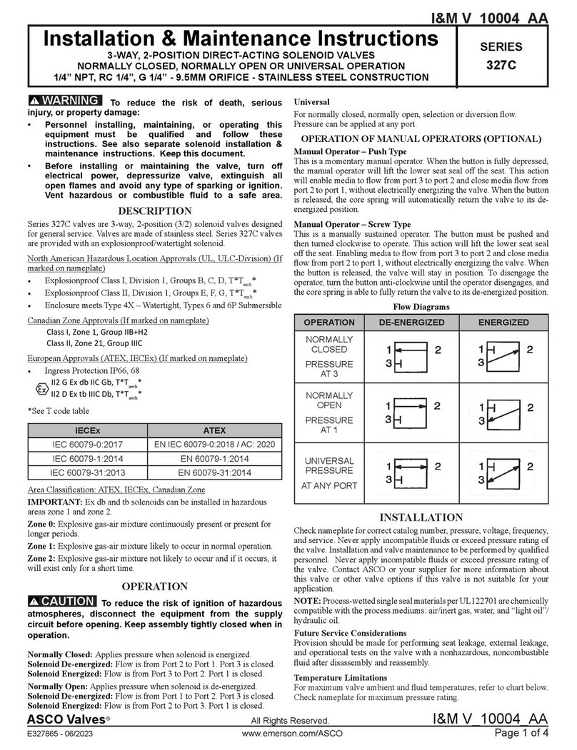
Normally Closed (Pressure at Port 1)
Solenoid De-energized: Flow is from Port 2 to Port 3. Port 1 is
closed.
Solenoid Energized: Flow is from Port 1 to Port 2. Port 3 is closed.
Breather Function: Allows for spring side of a spring return actuator to
vent at all times through valve e haust port 3. IMPORT NT: Because
of the breather function, the use of a metering / flow control device at
exhaust port 3 (to control actuator speed) is not recommended.
NOTICE: No minimum operating pressure differential required.
SOLENOID
DE-ENERGIZED
SOLENOID
ENERGIZED
FLOW DIAGRAMS
12
3
12
3
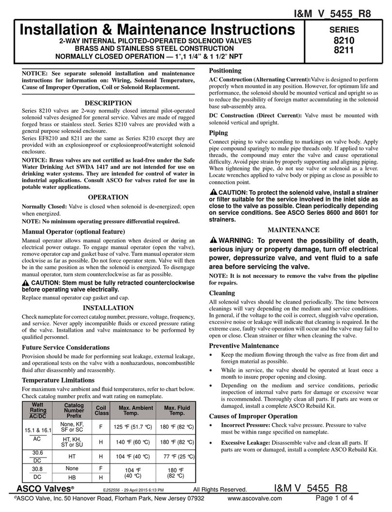
Manual Operation
Manual operator (optional feature) allows manual operation when
desired or during an electrical power outage. Depending upon valve
requirements, two types of manual operators are available:
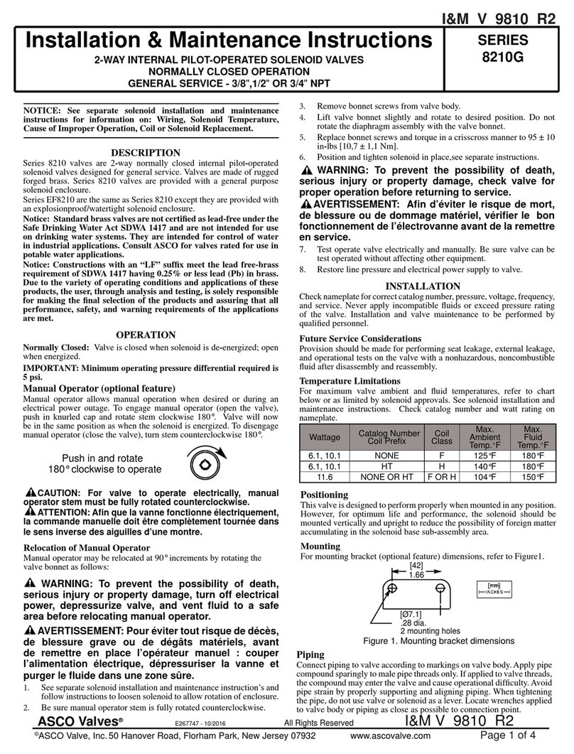
Momentary Push Type (Suffix MO) Manual Operator
To engage push type manual operator, push stem at base of valve body
upward as far as possible. Valve will now be in the same position as
when the solenoid is energized. To disengage manual operator,
release stem. Manual operator will return to original position.
Maintained Screw Type (Suffix MS) Manual Operator
To engage screw type manual operator, turn red knob clockwise until
it hits a stop. Valve will now be in the same position as when solenoid
is energized. Rotate knob fully counterclockwise to disengage.
CAUTION: For valve to operate electrically, manual
operator must be fully disengaged.
INST LL TION
Check nameplate for correct catalog number, pressure, voltage,
frequency, and service. Never apply incompatible fluids or e ceed
pressure rating of the valve. Installation and valve maintenance to be
performed by qualified personnel.
Future Service Considerations
Provision should be made for performing seat leakage, e ternal
leakage, and operational tests on the valve with a nonhazardous,
noncombustible fluid after disassembly and reassembly.
Temperature Limitations
See separate solenoid Installation and Maintenance Instructions for
ma imum ambient temperature Ma imum fluid temperature is
180_F (82_C)
Positioning
Valve may be mounted in any position.
Mounting Solenoid Valve to N MUR ctuator
Valves are supplied with a hardware kit containing two port gaskets
and three sets of mounting screws; sizes: M5, .190-24 UNC-2A and
.190-32 UNF-2A. Align port 2 and 3 port gaskets and solenoid
valve on actuator. Then install two he head screws in offset center
holes on either side. Hand thread screws a few turns into actuator.
Then tighten screws evenly using a 5/16I or 8 mm wrench.
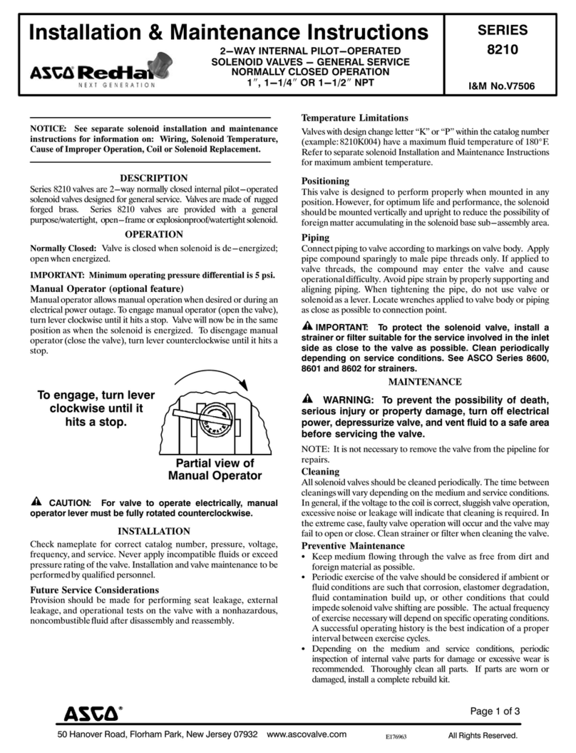
Figure 1 Mounting Dimensions
1 26
[32]
95
[24]
2 mounting holes locating hole
port gaskets (2)
32
Piping
Apply pipe compound sparingly to male pipe threads only. If applied
to valve threads the compound may enter the valve and cause
operational difficulty. Avoid pipe strain by properly supporting and
aligning piping. When tightening the pipe, do not use valve or
solenoid as a lever. Locate wrenches applied to valve body or piping
as close as possible to connection point.
NOTE: The e haust and/or pressure lines may be restricted to
control actuator speed.
CAUTION: To protect the solenoid valve, install a strainer
or filter, suitable for the service involved, in the inlet side as
close to the valve as possible. Clean periodically depending
on service conditions. See ASCO Series 8600, 8601, and 8602
for strainers.
50 Hanover Road, Florham Park, New Jersey 07932 www ascovalve com
Page 2 of 3 I&M No V7569
M INTEN NCE
WARNING: To prevent the possibility of
death, serious injury or property damage, turn off
electrical power, depressurize valve, and vent
fluid to a safe area before servicing the valve.
Cleaning
All solenoid valves should be cleaned periodically. The time between
cleaning will vary depending on the medium and service conditions.
In general, if the voltage to the coil is correct, sluggish valve operation,
e cessive noise, or leakage will indicate that cleaning is required. In
the e treme case, faulty valve operation will occur and the valve may
fail to shift. Clean strainer or filter when cleaning the valve.
Preventive Maintenance
SKeep medium flowing through the valve as free from dirt and
foreign material as possible.
SPeriodic e ercise of the valve should be considered if ambient or
fluid conditions are such that corrosion, elastomer degradation,
fluid contamination build up, or other conditions that could
impede solenoid valve shifting are possible. The actual frequency
of e ercise necessary will depend on specific operating conditions.
A successful operating history is the best indication of a proper
interval between e ercise cycles.
SDepending on the medium and service conditions, periodic
inspection of internal valve parts for damage or e cessive wear is
recommended. Thoroughly clean all parts. If parts are worn or
damaged, install a complete rebuild kit.
Causes of Improper Operation
SIncorrect Pressure: Check valve pressure. Pressure to valve must
be within range specified on nameplate.
SExcessive Leakage: Disassemble valve and install a complete
ASCO Rebuild Kit.
Valve Disassembly (Refer to Figures 2 & 3)
1. Disassemble valve in an orderly fashion using e ploded view for
identification of parts.
2. Disconnect electrical hookup to solenoid and piping to valve
body.
3. Remove solenoid, see separate instructions.
4. Remove two he head mounting screws from offset holes in
valve body using a 5/16I or 8 mm wrench.
5. Unscrew solenoid base sub-assembly from valve body. Then
remove solenoid base gasket and core assembly with core
spring and core guide.
6. Unscrew end cap or optional manual operator and remove disc
holder spring, disc holder assembly and end cap gasket from
valve body.
7. All parts are now accessible for cleaning or replacement. If
parts are worn or damaged, install a complete ASCO Rebuild
Kit.
Valve Reassembly
1. Reassemble valve using e ploded views for identification and
placement of parts.
2. Lubricate all gaskets with DOW CORNINGr 200 Fluid
lubricant or an equivalent high-grade silicone fluid.
NOTE: Solenoid base gasket and end cap gasket are identical.
3. Reinstall end cap gasket, disc holder assembly, disc holder
spring and end cap or optional manual operator in valve body.
Torque end cap to 175 ± 25 in-lbs [19,8 ± 2,8 Nm].
4. Position solenoid base gasket in valve body.
5. Install core assembly with core spring and guide into solenoid
base sub-assembly and engage with valve body.
6. Torque solenoid base sub-assembly to 175 ± 25 in-lbs
[19,8 ± 2,8 Nm].
7. Reinstall valve on actuator, see Mounting Solenoid Valve To
NAMUR Actuator section.
8. Reinstall solenoid and make electrical connections, see
separate instructions.
9. Install piping to valve, see Piping section.
WARNING: To prevent the possibility of death,
serious injury or property damage, check valve for
proper operation before returning to service. Also
perform internal seat and external leakage tests
with a nonhazardous, noncombustible fluid.
10. Restore line pressure and electrical power supply to valve.
11. After maintenance is completed, operate the valve a few times
to be sure of proper operation. A metallic click indicates the
solenoid is operating.
ORDERING INFORM TION
FOR SCO REBUILD KITS
Parts marked with an asterisk (*) in the e ploded view are supplied in
Rebuild Kits. When Ordering Rebuild Kits for ASCO valves, order
the Rebuild Kit number stamped on the valve nameplate. If the
number of the kit is not visible, order by indicating the number of kits
required, and the Catalog Number and Serial Number of the valve(s)
for which they are intended.
50 Hanover Road, Florham Park, New Jersey 07932 www ascovalve com
Page 3 of 3I&M No V7569
Figure 2 Series 8320 valve without solenoid
solenoid base
sub-assembly
core assembly
end cap
disc holder spring
body gasket (2)
body
disc holder assembly
solenoid base gasket
with spring
end cap gasket
core guide
Indicates that these
parts are included
in ASCO Rebuild Kit
mounting screw (2)
5/16I or 8 mm wrench
push type screw type
Manual Operator
(Optional Feature)
Replaces End Cap
MO MS

Other ASCO Valves Control Unit manuals

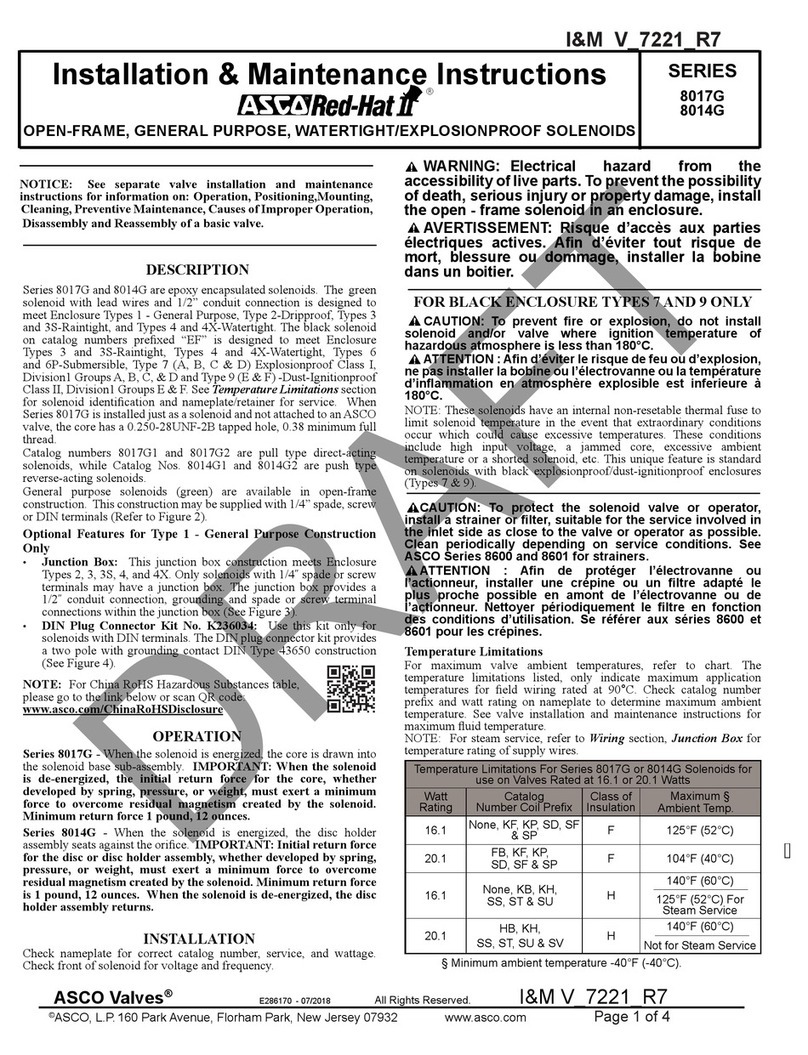
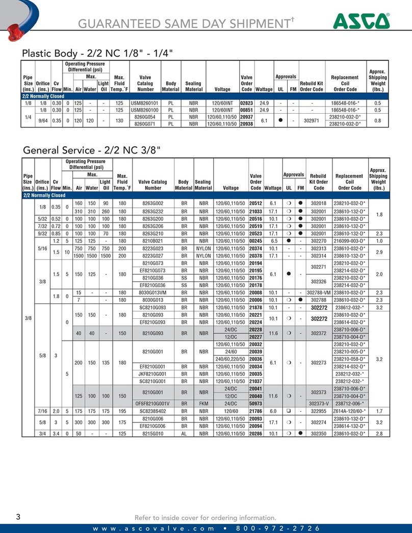
ASCO Valves 8210 Series Installation and operating instructions

ASCO Valves

ASCO Valves 8210 Series Installation and operating instructions

ASCO Valves 8004 Series Installation and operating instructions

ASCO Valves

ASCO Valves 8004 Series Installation and operating instructions

ASCO Valves 8210 Series Installation and operating instructions

ASCO Valves

ASCO Valves 8210 Series Installation and operating instructions

ASCO Valves 8210G Series Installation and operating instructions

ASCO Valves

ASCO Valves 8210G Series Installation and operating instructions

ASCO Valves 8214(200) Series Installation and operating instructions

ASCO Valves

ASCO Valves 8214(200) Series Installation and operating instructions

ASCO Valves 8222 Series Installation and operating instructions

ASCO Valves

ASCO Valves 8222 Series Installation and operating instructions

ASCO Valves Red-Hat II 8017G Series Installation and operating instructions

ASCO Valves

ASCO Valves Red-Hat II 8017G Series Installation and operating instructions

ASCO Valves 8214 Series Installation and operating instructions

ASCO Valves

ASCO Valves 8214 Series Installation and operating instructions

ASCO Valves 8210 Series Installation and operating instructions

ASCO Valves

ASCO Valves 8210 Series Installation and operating instructions

ASCO Valves 8210 Series Installation and operating instructions

ASCO Valves

ASCO Valves 8210 Series Installation and operating instructions

ASCO Valves 8210 Series Installation and operating instructions

ASCO Valves

ASCO Valves 8210 Series Installation and operating instructions

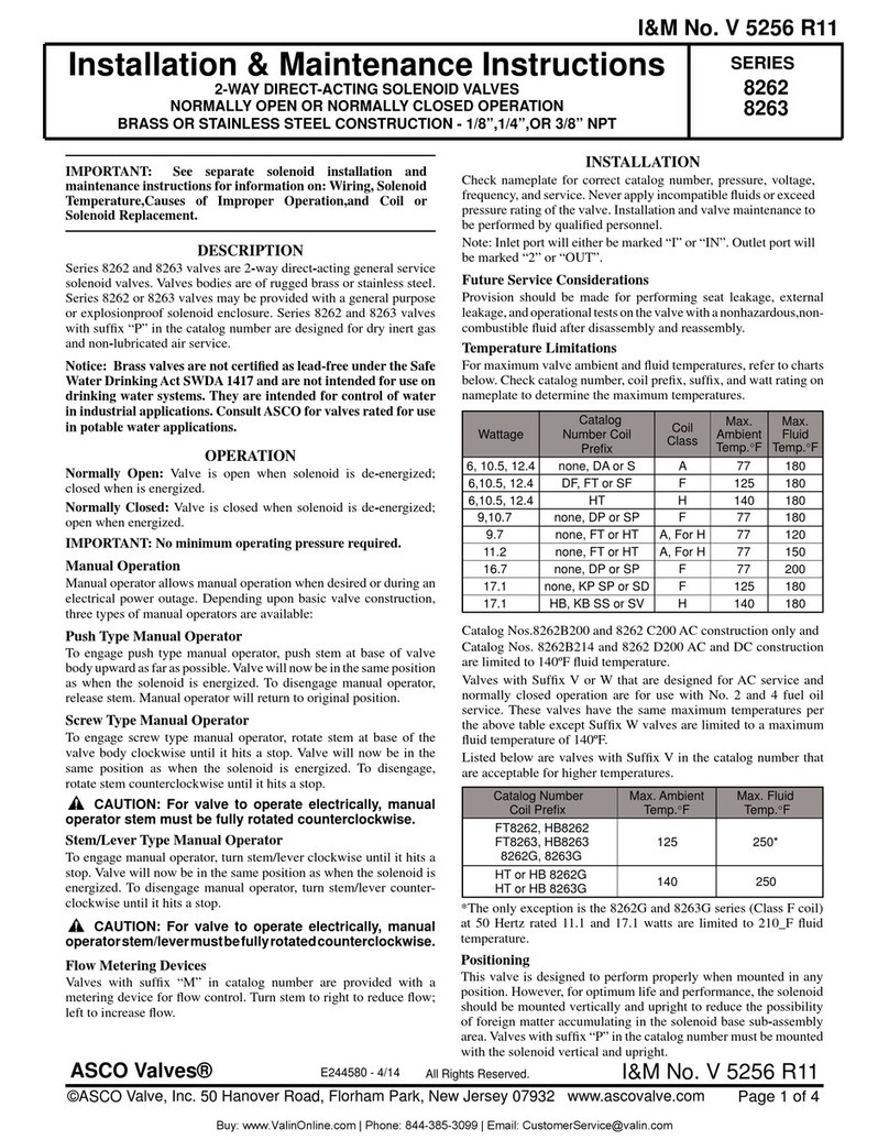
ASCO Valves 8263 Series Installation and operating instructions

ASCO Valves

ASCO Valves 8263 Series Installation and operating instructions

ASCO Valves 8210 Series Installation and operating instructions

ASCO Valves

ASCO Valves 8210 Series Installation and operating instructions

ASCO Valves 8044 Series Installation and operating instructions

ASCO Valves

ASCO Valves 8044 Series Installation and operating instructions

ASCO Valves 327C Series Installation and operating instructions

ASCO Valves

ASCO Valves 327C Series Installation and operating instructions

ASCO Valves EV8308G360 Installation and operating instructions

ASCO Valves

ASCO Valves EV8308G360 Installation and operating instructions

ASCO Valves 8262 Series Installation and operating instructions

ASCO Valves

ASCO Valves 8262 Series Installation and operating instructions

ASCO Valves USM8260101 Installation and operating instructions

ASCO Valves

ASCO Valves USM8260101 Installation and operating instructions

Popular Control Unit manuals by other brands

EOS SBM App Module Setup and operation

EOS

EOS SBM App Module Setup and operation

ATEN KVMP CM1164 user manual

ATEN

ATEN KVMP CM1164 user manual

NXP Semiconductors freescale TWR-56F8200 quick start guide

NXP Semiconductors

NXP Semiconductors freescale TWR-56F8200 quick start guide

Flowserve AKH2A Technical manual

Flowserve

Flowserve AKH2A Technical manual

Honeywell VE4000 Series instruction sheet

Honeywell

Honeywell VE4000 Series instruction sheet

Nordelettronica NE355 S instruction manual

Nordelettronica

Nordelettronica NE355 S instruction manual

Hemisphere GPS Crescent P206 Integrator guide

Hemisphere GPS

Hemisphere GPS Crescent P206 Integrator guide

M-system R7L-EC8A instruction manual

M-system

M-system R7L-EC8A instruction manual

Parallax 32440 manual

Parallax

Parallax 32440 manual

ICP DAS USA PISO-CPM100U-D/T quick start

ICP DAS USA

ICP DAS USA PISO-CPM100U-D/T quick start

SMC Networks XLH16 Operation manual

SMC Networks

SMC Networks XLH16 Operation manual

Hach sc200 4-20 user manual

Hach

Hach sc200 4-20 user manual

ICP DAS USA PM-4324 Series quick start

ICP DAS USA

ICP DAS USA PM-4324 Series quick start

Viessmann 5096 Operation manual

Viessmann

Viessmann 5096 Operation manual

Swegon P.LEMMENS CB4 TAC4 REC installation manual

Swegon

Swegon P.LEMMENS CB4 TAC4 REC installation manual

SCHUNK GSM-P Assembly and operating manual

SCHUNK

SCHUNK GSM-P Assembly and operating manual

Supermicro MicroBlade 6119M-T2N user manual

Supermicro

Supermicro MicroBlade 6119M-T2N user manual

Telit Wireless Solutions GS2101M Series Command reference guide

Telit Wireless Solutions

Telit Wireless Solutions GS2101M Series Command reference guide

manuals.online logo
manuals.online logoBrands
  • About & Mission
  • Contact us
  • Privacy Policy
  • Terms and Conditions

Copyright 2025 Manuals.Online. All Rights Reserved.