manuals.online logo
Brands
  1. Home
  2. •
  3. Brands
  4. •
  5. ASCO Valves
  6. •
  7. Control Unit
  8. •
  9. ASCO Valves 8004 Series Installation and operating instructions

ASCO Valves 8004 Series Installation and operating instructions

Installation & Maintenance Instructions
GENERAL PURPOSE / RAINTIGHT / WATERTIGHT AND
RAINTIGHT / WATERTIGHT / EXPLOSIONPROOF SOLENOIDS
SERIES
8004
ASCO ValvesASCO Valves®®E310657 -E310657 - 01/202101/2021 All Rights Reserved.All Rights Reserved. I&M V_6796_HBI&M V_6796_HB
©©ASCO, L.P. 160 ParkASCO, L.P. 160 Park Avenue, Florham Park,Avenue, Florham Park, New Jersey 07932New Jersey 07932 www.emerson.comwww.emerson.com Page 1 of 2Page 1 of 2
I&M V_6796_HB
DESCRIPTION
Catalog Numbers WT8004A1 and EF8004A1 are thermoplastic
encapsulated pull-type solenoids for use with ASCO valves. These
solenoids have three lead wires with one wire for grounding and a
½” male conduit connection. Catalog No. WT8004A1 is designed
to meet Enclosure Type 1 - General Purpose, Types 3 and 3S -
Raintight, Types 4 and 4X - Watertight. Catalog No. EF8004A1
meets Enclosure Types 3 and 3S - Raintight, Types 4 and 4X -
Watertight, Types 6 and 6P - Submersible, Type 7 (A, B, C & D)
Explosionproof Class I, Division 1, Groups A, B, C, & D and Type
9 (E, F, & G) - Dust - Ignitionproof Class II, Division 1, Groups E,
F, & G. (See asterisks [*] below)
AC (6.3 W) voltages *
• 24, 100, 110, 120, 110-120, 220, 220-240 @ 50Hz
• 12, 24, 100, 110, 120, 240 @ 60Hz
DC (6.9 W) voltages *
• 6, 12, 24, 28, 48, 100, 120, 240
= Specific voltage is marked on coil
*= Div 1 voltages (UL/CSA, if marked) for EF prefix version. See
accompanying regional requirement cert (example, CCC/NEPSI)
for voltage, Ex protection and temperature limitations (if marked).
OPERATION
When the solenoid is energized, the core assembly is drawn into the
plugnut/core tube sub-assembly. When the solenoid is de-energized,
spring force returns the core assembly to the original position.
Enclosure Types 7 and 9 Only (EF8004A1)*
To prevent re or explosion, do not
install solenoid and/or valve where ignition temperature of
hazardous atmosphere is less than 160 °C. Open circuit before
disassembling. Do not exceed temperature limitations in chart
below. (See asterisk [*] in DESCRIPTION section).
Afin d’éviter le risque de feu
ou d’explosion, ne pas installer la bobine ou l’électrovanne ou
la température d’inflammation en atmosphère explosible est
inferieure à 160 °C. Ouvrez le circuit avant le désassemblage. Ne
pas dépasser les limites de température mentionnées dans le
tableau ci-dessous. (Voir l’astérisque [*] dans la section descriptive).
Temperature Limitations
For maximum ambient/fluid temperatures, refer to chart.
See valve installation and maintenance instructions for valve
temperature limitations.
Catalog Numbers Construction Ambient/Fluid Temperature
WT8004A1
AC Construction (6.3W)
-40 °F(-40 °C) to 140 °F (60 °C)
DC Construction (6.9W)
-40°F(-40 °C) to 125 °F (52°C)
EF8004A1*
AC Construction (6.3W)
-40 °F(-40 °C) to 104 °F (40 °C)
DC Construction (6.9W)
-40 °F(-40 °C) to 125 °F (52 °C)
(See asterisk [*] in DESCRIPTION section)
Positioning
Solenoid may be mounted in any position
Valve Mounting
This solenoid is assembled to a valve that must be rigidly supported
using the valve body mounting provisions.
WARNING
ADVERTISSEMENT
NOTICE: See separate valve installation and maintenance
instructions for information on: Operation, Positioning, Mounting,
Cleaning, Preventive Maintenance, Cause of Improper Operation,
Disassembly and Reassembly of basic valve.
Wiring
To reduce the risk of electrocution, re, or
property damage, wiring must comply with local codes and
the National Electrical Code (NEC).
Pour réduire les risques
d’électrocution, d’incendie ou de dommages matériels, le
câblage doit être conforme aux codes locaux et au NEC.
To facilitate wiring, the solenoid may be rotated 360° in 90°
increments. To rotate solenoid, remove retaining cap (if present)
and four mounting screws, reposition solenoid and replace screws
and retaining cap (if present). Torque screws evenly in a crisscross
manner to 12 in -lbs [1,3 Nm]. Torque retaining cap to 10-12 in - lbs
[1,1-1,3 Nm] using a 21/32” socket.
The solenoid must be grounded with
included grounding wire - do not rely on process pipes for
grounding.
La bobine doit être mise
à la terre avec le l de terre inclus - ne vous ez pas aux
canalisations pour la mise à la terre.
Solenoids have a ½ - 14 NPT male thread. For connection to rigid
metal conduit, metal type NPT electrical fittings should be used or
use ASCO Part Number 264568-001, supplied.
For the explosionproof solenoid (EF8004A1), the female ½ - 14
NPT conduit connector comes preassembled and makes up the full
hazardous location solenoid assembly. Any additional required
electrical fittings must be approved for use in hazardous locations.
Solenoid Temperature
Standard solenoids are designed for continuous duty service. When
the solenoid is energized for a long period, the solenoid becomes
hot and can be touched by hand only for an instant. This is a safe
operating temperature.
MAINTENANCE
To prevent the possibility of death,
serious injury or property damage, turn o󰀨 electrical power,
depressurize solenoid valve and vent uid to a safe area
before servicing,
Afin d’éviter tout risque de mort,
blessure ou dommage, couper l’alimentation électrique,
dépressuriser la vanne ou l’électrovanne et vidanger le fluide en
zone non dangereuse avant toute maintenance.
Potential Electrostatic Charging Hazard.
Use wet or damp cloth when cleaning coil, non-metallic pilot
or valve body (if applicable).
Risque de charges électrostatiques
en atmosphères explosibles. Utiliser un chi󰀨on humide
ou mouillé lors du nettoyage de la bobine, Corps de pilote
ou de vanne non métallique (si applicable).
Cleaning (also, see above)
All solenoid operators and valves should be cleaned periodically.
Time between cleaning will vary depending on medium and service
conditions. In general, if the voltage to the solenoid is correct,
sluggish valve operation, excessive noise or leakage will indicate
that cleaning is required. In the extreme case faulty valve or
solenoid operation will occur and the valve or solenoid may fail to
shift. Clean strainer or filter when cleaning the valve.
WARNING
ADVERTISSEMENT
WARNING
ADVERTISSEMENT
WARNING
ADVERTISSEMENT
WARNING
ADVERTISSEMENT
Torque Chart
Part Name Torque Value Inch-Pounds Torque Value Newton-Meters
Mounting Screws 10-14 0,7-1,1
Cap 10-12 1,1-1,4
Torque Chart
Part Name Torque Value Inch-Pounds Torque Value Newton-Meters
Mounting Screws 10-14 0,7-1,1
Cap 10-12 1,1-1,4
Page 2 of 2 I&M No. V 6796_R6
©ASCO Valve, Inc. 160 Park Avenue, Florham Park, New Jersey 07932 www.asco.com
WT
Causes of Improper Operation
• Faulty Control Circuit: Check the electrical system by
energizing the solenoid. A metallic click signifi es that the
solenoid is operating. Absence of the click indicates loss of
power supply. Check for loose or blown fuses, open -circuited
or grounded solenoid, broken lead wires or splice connections.
• Burned-Out Solenoid: Check for open-circuited solenoid.
Check supply voltage; it must be the same as specifi ed on
nameplate and marked on the solenoid. Check ambient
temperature and check that the core is not jammed. If necessary,
replace pilot valve.
• Low Voltage: Check voltage across the solenoid leads.
Voltage must be at least 85% of rated voltage.
ORDERING INFORMATION FOR
REPLACEMENT PILOT VALVE WITH
SOLENOID
Specify valve Catalog Number, Solenoid Catalog Number,
Serial Number, Voltage and Frequency.
coil assembly
1/2-14 female NPT
preassembled on
EF version
coil assembly
1/2-14 NPT male
1/2-14 NPT male
cap (if supplied)
cap (if supplied)
Torque Chart
Part Name Torque Value Inch-Pounds Torque Value Newton-Meters
Mounting Screws 10-14 0,7-1,1
Cap 10-12 1,1-1,4
Page 2 of 2 I&M No. V 6796_R6
©ASCO Valve, Inc. 160 Park Avenue, Florham Park, New Jersey 07932 www.asco.com
WT
Causes of Improper Operation
• Faulty Control Circuit: Check the electrical system by
energizing the solenoid. A metallic click signifi es that the
solenoid is operating. Absence of the click indicates loss of
power supply. Check for loose or blown fuses, open -circuited
or grounded solenoid, broken lead wires or splice connections.
• Burned-Out Solenoid: Check for open-circuited solenoid.
Check supply voltage; it must be the same as specifi ed on
nameplate and marked on the solenoid. Check ambient
temperature and check that the core is not jammed. If necessary,
replace pilot valve.
• Low Voltage: Check voltage across the solenoid leads.
Voltage must be at least 85% of rated voltage.
ORDERING INFORMATION FOR
REPLACEMENT PILOT VALVE WITH
SOLENOID
Specify valve Catalog Number, Solenoid Catalog Number,
Serial Number, Voltage and Frequency.
coil assembly
1/2-14 female NPT
preassembled on
EF version
coil assembly
1/2-14 NPT male
1/2-14 NPT male
cap (if supplied)
cap (if supplied)
Page 2 of 2 I&M V_6796_HB
©ASCO, L.P. 160 Park Avenue, Florham Park, New Jersey 07932 www.emerson.com
Preventive Maintenance
• Keep the medium flowing through the solenoid valve as free
from dirt and foreign material as possible.
• While in service, the solenoid valve should be operated at least
once a month to ensure proper opening and closing.
• Depending on the medium and service conditions, periodic
inspection of internal valve parts for damage or excessive wear
is recommended. Thoroughly clean all parts. Replace any worn
or damaged parts.
Causes of Improper Operation
• Faulty Control Circuit: Check the electrical system by
energizing the solenoid. A metallic click signifies that the
solenoid is operating. Absence of the click indicates loss of
power supply. Check for loose or blown fuses, open -circuited
or grounded solenoid, broken lead wires or splice connections.
• Burned-Out Solenoid: Check for open-circuited solenoid.
Check supply voltage; it must be the same as specified on
nameplate and marked on the solenoid. Check ambient
temperature and check that the core is not jammed. If necessary,
replace pilot valve.
• Low Voltage: Check voltage across the solenoid leads. Voltage
must be at least 85% of rated voltage.
ORDERING INFORMATION FOR
REPLACEMENT PILOT VALVE
WITH SOLENOID
Specify valve Catalog Number, Solenoid Catalog Number, Serial
Number, Voltage and Frequency.

This manual suits for next models

2

Other ASCO Valves Control Unit manuals

ASCO Valves Red-Hat II 8017G Series Installation and operating instructions

ASCO Valves

ASCO Valves Red-Hat II 8017G Series Installation and operating instructions

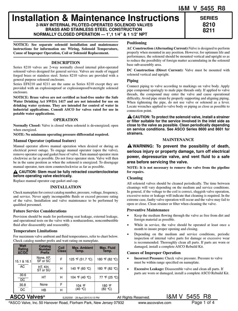
ASCO Valves 8210 Series Installation and operating instructions

ASCO Valves

ASCO Valves 8210 Series Installation and operating instructions

ASCO Valves 8214 Series Installation and operating instructions

ASCO Valves

ASCO Valves 8214 Series Installation and operating instructions

ASCO Valves 8210 Series Installation and operating instructions

ASCO Valves

ASCO Valves 8210 Series Installation and operating instructions

ASCO Valves 8210 Series Installation and operating instructions

ASCO Valves

ASCO Valves 8210 Series Installation and operating instructions

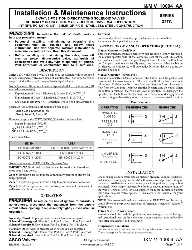
ASCO Valves 327C Series Installation and operating instructions

ASCO Valves

ASCO Valves 327C Series Installation and operating instructions

ASCO Valves 8214(200) Series Installation and operating instructions

ASCO Valves

ASCO Valves 8214(200) Series Installation and operating instructions

ASCO Valves 8210 Series Installation and operating instructions

ASCO Valves

ASCO Valves 8210 Series Installation and operating instructions

ASCO Valves 8210G Series Installation and operating instructions

ASCO Valves

ASCO Valves 8210G Series Installation and operating instructions

ASCO Valves 8210 Series Installation and operating instructions

ASCO Valves

ASCO Valves 8210 Series Installation and operating instructions

ASCO Valves 8262 Series Installation and operating instructions

ASCO Valves

ASCO Valves 8262 Series Installation and operating instructions

ASCO Valves EV8308G360 Installation and operating instructions

ASCO Valves

ASCO Valves EV8308G360 Installation and operating instructions

ASCO Valves 8222 Series Installation and operating instructions

ASCO Valves

ASCO Valves 8222 Series Installation and operating instructions

ASCO Valves USM8260101 Installation and operating instructions

ASCO Valves

ASCO Valves USM8260101 Installation and operating instructions

ASCO Valves 8044 Series Installation and operating instructions

ASCO Valves

ASCO Valves 8044 Series Installation and operating instructions

ASCO Valves 8263 Series Installation and operating instructions

ASCO Valves

ASCO Valves 8263 Series Installation and operating instructions

ASCO Valves 8320 Series Installation and operating instructions

ASCO Valves

ASCO Valves 8320 Series Installation and operating instructions

ASCO Valves 8210 Series Installation and operating instructions

ASCO Valves

ASCO Valves 8210 Series Installation and operating instructions

Popular Control Unit manuals by other brands

EOS SBM App Module Setup and operation

EOS

EOS SBM App Module Setup and operation

ATEN KVMP CM1164 user manual

ATEN

ATEN KVMP CM1164 user manual

NXP Semiconductors freescale TWR-56F8200 quick start guide

NXP Semiconductors

NXP Semiconductors freescale TWR-56F8200 quick start guide

Flowserve AKH2A Technical manual

Flowserve

Flowserve AKH2A Technical manual

Honeywell VE4000 Series instruction sheet

Honeywell

Honeywell VE4000 Series instruction sheet

Nordelettronica NE355 S instruction manual

Nordelettronica

Nordelettronica NE355 S instruction manual

Hemisphere GPS Crescent P206 Integrator guide

Hemisphere GPS

Hemisphere GPS Crescent P206 Integrator guide

M-system R7L-EC8A instruction manual

M-system

M-system R7L-EC8A instruction manual

Parallax 32440 manual

Parallax

Parallax 32440 manual

ICP DAS USA PISO-CPM100U-D/T quick start

ICP DAS USA

ICP DAS USA PISO-CPM100U-D/T quick start

SMC Networks XLH16 Operation manual

SMC Networks

SMC Networks XLH16 Operation manual

Hach sc200 4-20 user manual

Hach

Hach sc200 4-20 user manual

ICP DAS USA PM-4324 Series quick start

ICP DAS USA

ICP DAS USA PM-4324 Series quick start

Viessmann 5096 Operation manual

Viessmann

Viessmann 5096 Operation manual

Swegon P.LEMMENS CB4 TAC4 REC installation manual

Swegon

Swegon P.LEMMENS CB4 TAC4 REC installation manual

SCHUNK GSM-P Assembly and operating manual

SCHUNK

SCHUNK GSM-P Assembly and operating manual

Supermicro MicroBlade 6119M-T2N user manual

Supermicro

Supermicro MicroBlade 6119M-T2N user manual

Telit Wireless Solutions GS2101M Series Command reference guide

Telit Wireless Solutions

Telit Wireless Solutions GS2101M Series Command reference guide

manuals.online logo
manuals.online logoBrands
  • About & Mission
  • Contact us
  • Privacy Policy
  • Terms and Conditions

Copyright 2025 Manuals.Online. All Rights Reserved.