manuals.online logo
Brands
  1. Home
  2. •
  3. Brands
  4. •
  5. Asco
  6. •
  7. Control Unit
  8. •
  9. Asco 290 Series User manual

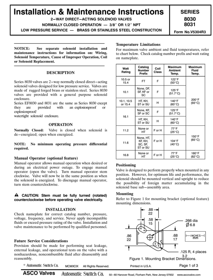
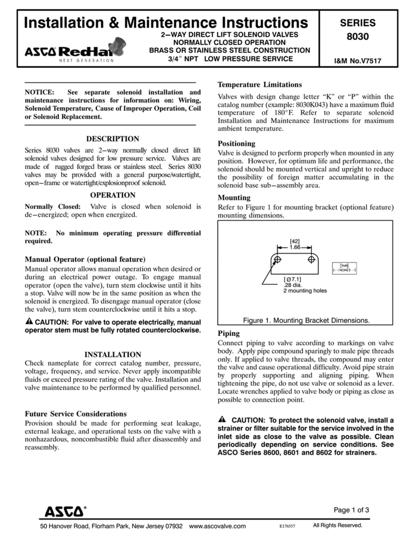
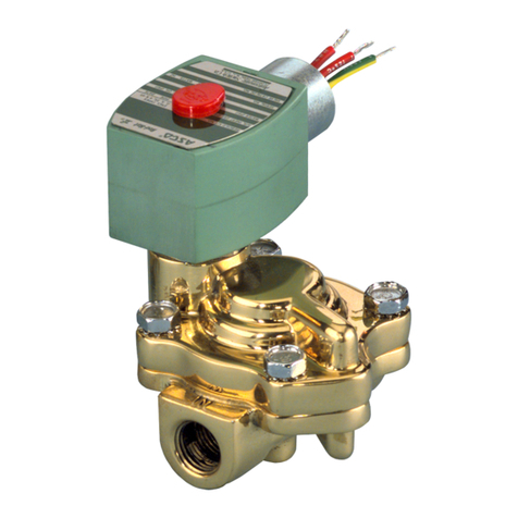
Asco 290 Series User manual

2 3 514361-001514361-001
INSTALLATION AND MAINTENANCE INSTRUCTIONS GB
INSTRUCTIONS D’INSTALLATION ET DE MAINTENANCE FR
INBETRIEBNAHME - UND WARTUNGSANLEITUNG DE
INSTRUCCIONES DE PUESTA EN MARCHA Y MANTENIMIENTO
ES
INSTRUZIONI DI MESSA IN SERVIZIO E MANUTENZIONE IT
ALGEMENE INSTALLATIE- EN ONDERHOUDSINSTRUCTIES
NL
INSTALLASJONS- OG VEDLIKEHOLDSINSTRUKSER NO
INSTALLATIONS- OCH UNDERHÅLLSINSTRUKTIONER SE
ASENNUS - JA HUOLTO-OHJEET FI
INSTALLATIONS - OG VEDLIGEHOLDSANVISNINGER
DK
INSTRUÇÕES DE INSTALAÇÃO E MANUTENÇÃO PT
ΟΔΗΓΙΕΣ ΤΟΠΟΘΕΤΗΣΗΣ ΚΑΙ ΣΥΝΤΗΡΗΣΗΣ
GR
POKYNY PRO INSTALACI A ÚDRŽBU
CZ
INSTRUKCJA MONTAŻU I KONSERWACJI
PL
TELEPÍTÉSI ÉS KARBANTARTÁSI ÚTMUTATÓ
HU
Инструкция по установке иобслуживанию
RU
МОНТАЖДАУ ЖƏНЕ ҚЫЗМЕТ КӨРСЕТУ НҰСҚАУЛАР KZ
설치
및유지
관리
지침
KR
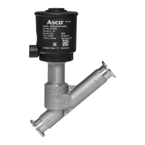
290 motorised valve
DC
AC ~
24 V 24 V ... 48 V 50/60 Hz 110 V ... 250 V 50/60 Hz
E290C--V0KA00V1 E290C--V0KA00UA E290C--V0KA00VW
E290C--V0XA00V1 E290C--V0XA00UA E290C--V0XA00VW
514361-001 / A
Availability, design and specifications are subject to change without notice. All rights reserved.
NBR / PBT «K»
NBR / PBT «K»
FPM / 316L «X» FPM / 316L «X»
M
/
31
6L
X
FP
M
/
31
6L
X
< 1,3 s
< 1,3 s
1
2
DC
AC
-20
-10
0
10
20
30
40
50
60
70
-10
0
10
20
30
40
50
60
70
80
90
100
110
120
130
140
150
160
F° C°
+50C°
-10C°
-20
-10
0
10
20
30
40
50
60
80
90
100
110
-10
0
10
20
30
40
50
60
70
80
90
100
110
120
130
140
150
160
170
180
190
200
210
F° C°
+90C°
-10C°
RECOMMENDATION FOR MAXIMUM DUTY CYCLE
-20
-10
0
10
20
30
40
50
60
70
-10
0
10
20
30
40
50
60
70
80
90
100
110
120
130
140
150
160
F° C°
+20C°
9 cycles/min
-20
-10
0
10
20
30
40
50
60
70
-10
0
10
20
30
40
50
60
70
80
90
100
110
120
130
140
150
160
F° C°
+50C°
4 cycles/min
max.
NBR / PBT «K»
PMA (Max. allowable pressure)
10 bar max.
flow
coefficient
Kv
operating pressure
differential (bar)
min.
max.
air
water
oil
(m3/h)
(l/min)
NBR / PBT «K»
3/8
3/8
2,7
2,7
45
45 06
1/2
1/2
3,8
3,8
63
63 05
3/4
3/4
6
6
100
100 04
OPERATING CONDITIONS
4 5 514361-001514361-001
4 cycles/min
9 cycles/min
2 cycles/min
2 cycles/min
+120C°
-10C°
+50C°
+20C°
+145C°
-20
-10
0
10
20
30
40
50
60
80
90
100
110
120
130
140
150
-10
0
10
20
30
40
50
60
70
80
90
100
110
120
130
140
150
160
170
180
190
200
210
220
230
240
250
260
270
280
F°C°
-20
-10
0
10
20
30
40
50
60
70
-10
0
10
20
30
40
50
60
70
80
90
100
110
120
130
140
150
160
F° C°
+50C°
-10C°
+20C°
+40C°
< 1,3 s
< 1,3 s
1
2
DC
AC
RECOMMENDATION FOR MAXIMUM DUTY CYCLE
FPM / 316L «X»
OPERATING CONDITIONS
PMA (Max. allowable pressure)
10 bar max.
flow
coefficient
Kv
operating pressure
differential (bar)
min.
max.
air
water
oil steam
(m3/h)
(l/min)
NBR / PBT «K»
3/8
3/8
2,7
2,7
45
45 06 4
1/2
1/2
3,8
3,8
63
63 05 4
3/4
3/4
6
6
100
100 04 4
1
2
DC
AC
✓✓
✓✓
MOUNTING «K» + «X»
«K»
6 7 514361-001514361-001
AB AB
FR fermeture ouverture NL sluiten openen
DE Schließen Öffnen PT fecho abertura
ES cierre apertura RU закрытие открытие
IT chiusura apertura KZ жабу ашу
INIT PHASE GB PHASE
D’INITIALISATION FR INITIALISATIONSPHASE DE
FASE INICIACIÓN ES FASE DI
INIZIALIZZAZIONE IT INITIALISATIEFASE NL
FASE INICIAL PT ФАЗА ИНИЦИАЛИЗАЦИИ RU БАСТАПҚЫ ФАЗА KZ
+ AC
FUNCTIONNING
DIAGRAM GB DIAGRAMME DE
FONCTIONNEMENT FR FUNKTIONSSCHEMA DE
DIAGRAMA DE
FUNCIONAMIENTO ES DIAGRAMMA DI
FUNZIONAMENTO IT WERKING SCHEMA NL
DIAGRAMA DE
FUNCIONAMENTO PT СХЕМА
РАБОТЫ RU ЖҰМЫС ІСТЕУ
ДИАГРАММАСЫ
KZ
AC
DC
1
21
2
A
closing
orange
DC
control voltage
state
state
valve state
open
close
position feedback
signal
state
state
voltage power
supply
state
state
t
t
t
1,3 s 1,3 s
t
1
0
1
0
1
0
24 V
±10 % DC
24 V ... 48 V
±10 %
AC ~
110 V ... 250 V AC ~
24 V
±10 % DC
24 V ... 48 V
±10 %
AC ~
24 V
±10 % DC
24 V ... 48 V
±10 %
AC ~
110 V ... 250 V AC ~
1
2
LED
LED
valve OPEN valve CLOSED valve MOVES TO OPEN valve MOVES TO CLOSE
GB
green orange green flashing orange flashing
FR
verte orange verte clignotante orange clignotante
DE
grün orange grün blinkend orange blinkend
ES
verde naranja verde intermitente naranja intermitente
IT
verde arancione verde lampeggiante arancione lampeggiante
NL
groen oranje groen knipperend oranje knipperend
PT
verde laranja verde intermitente laranja intermitente
RU
зеленый оранжевый зеленый мигающий оранжевый мигающий
KZ
жасыл сарғылт жасыл жыпықтайтын сарғылт жыпықтайтын
LED
1
2
LED
DC
24 V DC
24 V ... 48 V
±10%
AC ~ / 50-60 Hz
110 V ... 250 V AC ~ / 50-60 Hz
(NBR / PBT «K» - FPM / 316L «X»)
AC
DC
AC
8 9 514361-001514361-001
124 V
20 V
3control
4feedback signal
88122615
(ISO 4400 / EN 175301-803, form A)
Ø 6-10 mm
1
23
4
DC
12 W in operation, 0 W hold
Max. pic current: 0,7 A
Ripple 5%
Motor
24 V DC
(NBR / PBT «K» - FPM / 316L «X»)
24 V DC
+
=F
items N.m
Inch.pounds
A0,4 ±0,05 3,2 ±0,4
B0,4 ±0,05 3,2 ±0,4
124 V
20 V
3control
4feedback signal
A
DC
1
2
3
4 ( )
B
IP65
24 V DC
(NBR / PBT «K» - FPM / 316L «X»)
10 11 514361-001514361-001
FR DE ES IT
(I) entrée Eingang entrada input
(II) signal de retour Stellungsrückmeldung Retorno de estado ritorno
(III) commutateur de commande
ou relai Steuerschalter oder relais Conmutador de mando o
relé
Commutatore di comando
o relé
(IV) sortie Ausgang salida output
(V) alimentation électrique Spannungsversorgung Alimentación eléctrica Alimentazione elettrica
4
3
1
20V
24V
Output (IV)
PLC
Input (I)
1
2
34
power supply (V)
feedback
signal (II) 4
3
1
20V
24V
PLC
Input (I)
1
2
34
control switch
or relay CMD (III)
power supply (V)
feedback
signal (II)
NL PT RU KZ
(I) input entrada вход кіріс
(II) terugkeer naar stand retorno de estado возврат состояния кері байланыс сигналы
(III) regelschakelaar of relais comutador de comando
ou relé CMD
контрольный
переключатель или реле
басқару қосқышы немесе
реле
(IV) output saída выход шығыс
(V) voeding alimentação elétrica источник питания қуат көзі
124 V
20 V
3control
4feedback signal
124 V
20 V
3control
4feedback signal
1
2
3
4
1
2
3
4
24 V
±10 %
DC
(NBR / PBT «K» - FPM / 316L «X»)
DC
P290CA430078001 (110 V ... 250 V /50-60 Hz)
P290CA438907001 (24 V ... 48 V
±10 %
/50-60 Hz)
24 V DC +
=
AC DC
IP65
AC DC
DC
AC DC
24 V ... 48 V
±10%
AC ~ / 50-60 Hz
110 V ... 250 V AC ~ / 50-60 Hz
(NBR / PBT «K» - FPM / 316L «X»)
AC
12 13 514361-001514361-001
AC
24 V ... 48 V
C
1
2
3
4
1phase (Ph)
2neutral (N)
3control
4feedback signal
B
AC
24 V ... 48 V
AC
24 V ... 48 V
P290CA438907001
F
items N.m
Inch.pounds
B0,4 ±0,05 3,2 ±0,4
C0,4 ±0,05 3,2 ±0,4
88122615
Ø 6-10 mm
(ISO 4400 / EN 175301-803, form A)
IP65
24 V ... 48 V
±10 %
AC ~ / 50-60 Hz
(NBR / PBT «K» - FPM / 316L «X»)
AC 110 V ... 250 V AC ~ / 50-60 Hz
(NBR / PBT «K» - FPM / 316L «X»)
F
items N.m
Inch.pounds
B0,4 ±0,05 3,2 ±0,4
C0,4 ±0,05 3,2 ±0,4
C
1
2
3
1
2
3
1phase (Ph)
2neutral (N)
3control
AC
88122615
Ø 6-10 mm
(ISO 4400 / EN 175301-803, form A)
B
AC
110 V ... 250 V
AC
110 V ... 250 V
AC
110 V ... 250 V
P290CA430078001
IP65
AC
14 15 514361-001514361-001
F
items N.m
Inch.pounds
A0,4 ±0,05 3,2 ±0,4
IP65
P290CA430078001
P290CA438907001
AC
24 V ... 48 V
±10%
AC ~ / 50-60 Hz
110 V ... 250 V AC ~ / 50-60 Hz
(NBR / PBT «K» - FPM / 316L «X»)
A
AC
FR DE ES IT
(I) entrée Eingang entrada input
(II) signal de retour Stellungsrückmeldung Retorno de estado ritorno
(III) commutateur de commande
ou relai Steuerschalter oder relais Conmutador de mando o
relé
Commutatore di comando
o relé
NL PT RU KZ
(I) input entrada вход кіріс
(II) terugkeer naar stand retorno de estado возврат состояния кері байланыс сигналы
(III) regelschakelaar of relais comutador de comando
ou relé CMD
контрольный
переключатель или реле
басқару қосқышы немесе
реле
1phase (Ph)
2neutral (N)
3control
4feedback signal
1phase (Ph)
2neutral (N)
3control
4feedback signal
3
1
2N
Ph
PLC
1
2
3
~
4
24 V..48 V
4
feedback
signal (II)
3
1
2
PLC
1
2
3
24 V..48 V
N
Ph ~
4
4Input (I)
feedback
signal (II)
24 V ... 48 V
±10 %
AC ~ / 50-60 Hz
(NBR / PBT «K» - FPM / 316L «X»)
Input (I)
Control switch or
relay CMD (III)
Control switch or
relay CMD (III)
3
4
1
23
4
1
2
AC
16 17 514361-001514361-001
FR DE ES IT
(III) commutateur de commande
ou relai Steuerschalter oder relais Conmutador de mando o
relé
Commutatore di comando
o relé
NL PT RU KZ
(III) regelschakelaar of relais comutador de comando
ou relé CMD
контрольный
переключатель или реле
басқару қосқышы немесе
реле
1phase (Ph)
2neutral (N)
3control
1phase (Ph)
2neutral (N)
3control
3
1
2
3
1
2
3
1
2N
Ph
PLC
1
2
3
24 V
110 V..250 V
~
3
1
2
PLC
1
2
3
24 V
110 V..250 V
N
Ph ~
110 V ... 250 V AC ~ / 50-60 Hz
(NBR / PBT «K» - FPM / 316L «X»)
Control switch or
relay CMD (III) Control switch or
relay CMD (III)
AC
cut in power supply during a manoeuvre
GB
coupure de l’alimentation pendant une manoeuvre
FR
Spannungsunterbrechung während eines Stellvorgangs
DE
corte de la alimentación durante una maniobra
ES
Interruzione dell’alimentazione durante una manovra
IT
voedingsonderbreking tijdens besturing
NL
corte de alimentação durante uma manobra
PT
отключение питания во время маневра
RU
маневр кезінде қуат көзін қосу
KZ
power supply after control level
GB
alimentation après commande
FR
Versorgung nach Ansteuerung
DE
alimentación después del pilotaje
ES
Alimentazione dopo il comando
IT
voeding na regelniveau
NL
alimentação após comando
PT
подача питания после контрольного уровня
RU
бақылау деңгейінен кейінгі қуат көзі
KZ
cut in power supply valve open
GB
coupure de l’alimentation vanne ouverte
FR
Spannungsunterbrechung bei geöffnetem Ventil
DE
corte de la alimentación válvula abierta
ES
Interruzione alimentazione valvola aperta
IT
voedingsonderbreking geopende klep
NL
corte de alimentação válvula aberta
PT
отключение питания открыт клапан
RU
клапан ашық кезде қуат көзін қосу KZ
loss of power supply during valve closing
GB
perte d’alimentation durant la fermeture de la vanne
FR
Spannungsverlust während des Schließens des Ventils
DE
Pérdida de alimentación durante el cierre de la válvula
ES
perdita di alimentazione durante chiusura valvola
IT
voedingsverlies tijdens sluiten van klep
NL
perda de alimentação durante o fecho da válvula
PT
потеря питания во время закрытия клапана
RU
клапан жабылған кездегі қуат көзінің шығыны KZ
t
t
t
t
1
0
open
1
0
t
t
t
t
control voltage
1 (state)
0 (state)
1 (state)
0 (state)
valve state
open
close
voltage power supply
position feedback signal
close
0
0
V supply
V
supply
24 V
±10 %
DC / 24 V ... 48 V
±10 %
AC ~ / 110 V ... 230 V AC ~
V
supply
0
t
t
t
t
t
t
t
t
control voltage
1 (state)
0 (state)
open
voltage power supply
position feedback signal
1 (state)
0 (state)
close
valve state
open
close
1
0
0
1
0
V supply
FUNCTIONNING
DIAGRAM GB DIAGRAMME DE
FONCTIONNEMENT FR FUNKTIONSSCHEMA DE
DIAGRAMA DE
FUNCIONAMIENTO ES DIAGRAMMA DI
FUNZIONAMENTO IT WERKING SCHEMA NL
DIAGRAMA DE
FUNCIONAMENTO PT СХЕМА
РАБОТЫ RU ЖҰМЫС ІСТЕУ
ДИАГРАММАСЫ
KZ
DC
AC
18 19 514361-001514361-001
Fail close option
DC
AC
DEFAULT DIAGRAMS
control voltage
t
t
t
t
min 30s
1
0
1
0
0
control voltage
0t
t
t
< 1 s < 1 s
≥30 s
1
0
1
0
valve state
valve state
open
open
close
close
voltage power
supply
voltage power
supply
V supply V supply
position feedback
signal
position feedback
signal
control voltage
t
t
t
t
min 30s
1
0
1
0
0
valve state
open
close
voltage power
supply
V supply
position feedback
signal
ASCO SAS
53 rue de la Beauce, 28110 Luce
775 729 098 RCS Chartres

Other manuals for 290 Series

8

This manual suits for next models

1

Other Asco Control Unit manuals

Asco 8262 series Installation and operating instructions

Asco

Asco 8262 series Installation and operating instructions

Asco 8210 Series Installation and operating instructions

Asco

Asco 8210 Series Installation and operating instructions

Asco 290 Series Instruction Manual

Asco

Asco 290 Series Instruction Manual

Asco 551 Series User manual

Asco

Asco 551 Series User manual

Asco 8401 Series User manual

Asco

Asco 8401 Series User manual

Asco 8210 series User manual

Asco

Asco 8210 series User manual

Asco 552 Series User manual

Asco

Asco 552 Series User manual

Asco 302 Series User manual

Asco

Asco 302 Series User manual

Asco 8342 series Instruction Manual

Asco

Asco 8342 series Instruction Manual

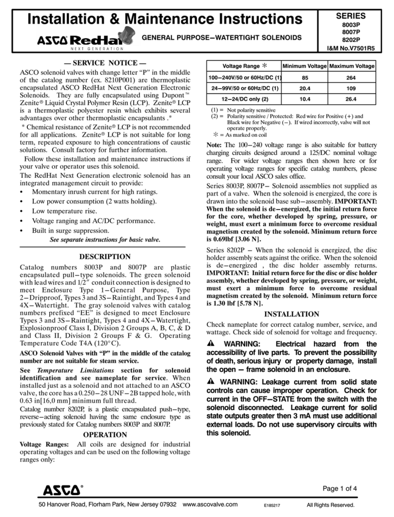
Asco RedHat  8317 Series Installation and operating instructions

Asco

Asco RedHat 8317 Series Installation and operating instructions

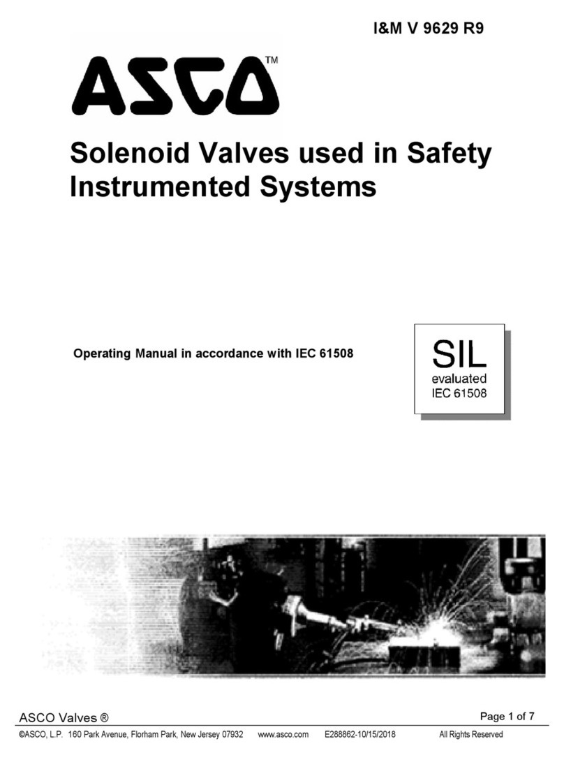
Asco Aseptic Positioner D Series Instruction Manual
Asco

Asco Aseptic Positioner D Series Instruction Manual

Asco 327 Series User manual

Asco

Asco 327 Series User manual

Asco JOUCOMATIC SENTRONIC 601 Series User manual

Asco

Asco JOUCOMATIC SENTRONIC 601 Series User manual

Asco 8040 Series Installation and operating instructions

Asco

Asco 8040 Series Installation and operating instructions

Asco 215 Series User manual

Asco

Asco 215 Series User manual

Asco 8214G54 Installation and operating instructions

Asco

Asco 8214G54 Installation and operating instructions

Asco 8030 Series Installation and operating instructions

Asco

Asco 8030 Series Installation and operating instructions

Asco 551 Series User manual

Asco

Asco 551 Series User manual

Asco 8317 Series Installation and operating instructions

Asco

Asco 8317 Series Installation and operating instructions

Asco RedHat 8321 Series Installation and operating instructions

Asco

Asco RedHat 8321 Series Installation and operating instructions

Asco 8215 Series Installation and operating instructions

Asco

Asco 8215 Series Installation and operating instructions

Asco 290 Series Instruction Manual

Asco

Asco 290 Series Instruction Manual
Asco 8316 Series Installation and operating instructions

Asco

Asco 8316 Series Installation and operating instructions

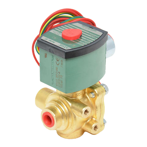
Asco MotorFlowD 610 Series User manual
Asco

Asco MotorFlowD 610 Series User manual

Popular Control Unit manuals by other brands

AXIOMTEK CEM700 Quick installation guide

AXIOMTEK

AXIOMTEK CEM700 Quick installation guide

Jetter JX3-PS1 user manual

Jetter

Jetter JX3-PS1 user manual

APV SAPM manual

APV

APV SAPM manual

Hardy Instruments A Series Operation and installation manual

Hardy Instruments

Hardy Instruments A Series Operation and installation manual

Stahl 9468/33 Series operating instructions

Stahl

Stahl 9468/33 Series operating instructions

Mitsubishi Q Series user manual

Mitsubishi

Mitsubishi Q Series user manual

GeneralAire MHX3 manual

GeneralAire

GeneralAire MHX3 manual

Siemens SINAMICS V60 Getting started

Siemens

Siemens SINAMICS V60 Getting started

Sensocon A1 Series Installation and operation manual

Sensocon

Sensocon A1 Series Installation and operation manual

Accutrol AVC5000 Installation & operation manual

Accutrol

Accutrol AVC5000 Installation & operation manual

Aube Technologies TH132 A owner's guide

Aube Technologies

Aube Technologies TH132 A owner's guide

SMC Networks XT323-4 Installation and maintenance manual

SMC Networks

SMC Networks XT323-4 Installation and maintenance manual

Honeywell NK295C Installation instruction

Honeywell

Honeywell NK295C Installation instruction

CAME Z Series manual

CAME

CAME Z Series manual

Dungs SAV 100065 MD instruction manual

Dungs

Dungs SAV 100065 MD instruction manual

Lincoln Quicklub 236-13857-1 user manual

Lincoln

Lincoln Quicklub 236-13857-1 user manual

Moxa Technologies MiiNePort W1 Series Quick installation guide

Moxa Technologies

Moxa Technologies MiiNePort W1 Series Quick installation guide

Hypex Electronics UcD Supply HG Mono user manual

Hypex Electronics

Hypex Electronics UcD Supply HG Mono user manual

manuals.online logo
manuals.online logoBrands
  • About & Mission
  • Contact us
  • Privacy Policy
  • Terms and Conditions

Copyright 2025 Manuals.Online. All Rights Reserved.