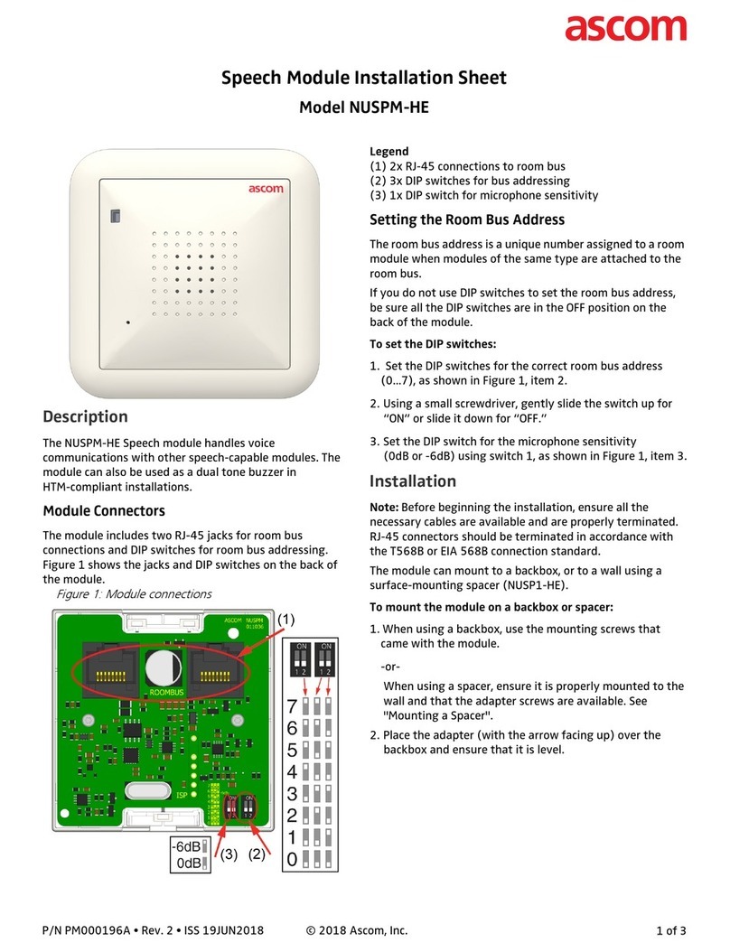
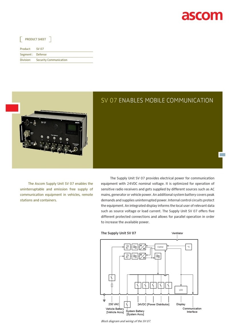
ASCOM Ascotel AIP 6350 User guide

ascom
Ascotel IntelliGate Telecommunication System
a
AIP 6350 / Office 35IP
System Manual


AIP 6350 / Office 35IP
3
Contents
1 Safety Instructions . . . . . . . . . . . . . . . . . . . . . . . . . . . . . . . . . . . . . . . .5
1.1 About the Products. . . . . . . . . . . . . . . . . . . . . . . . . . . . . . . . . . . . . . . . .5
1.2 Guidelines to this System Manual . . . . . . . . . . . . . . . . . . . . . . . . . . . . . .6
2 System Description . . . . . . . . . . . . . . . . . . . . . . . . . . . . . . . . . . . . . . .7
3 Initial Installation . . . . . . . . . . . . . . . . . . . . . . . . . . . . . . . . . . . . . . . . .9
3.1 Planning . . . . . . . . . . . . . . . . . . . . . . . . . . . . . . . . . . . . . . . . . . . . . . . . .9
3.1.1 Designing the System . . . . . . . . . . . . . . . . . . . . . . . . . . . . . . . . . . . . . .10
3.1.2 Assigning Call Numbers and IP Addresses . . . . . . . . . . . . . . . . . . . . . . .11
3.1.3 Network Planning . . . . . . . . . . . . . . . . . . . . . . . . . . . . . . . . . . . . . . . . .13
3.2 Installation . . . . . . . . . . . . . . . . . . . . . . . . . . . . . . . . . . . . . . . . . . . . . . 14
3.3 Configuring . . . . . . . . . . . . . . . . . . . . . . . . . . . . . . . . . . . . . . . . . . . . .14
3.3.1 Adding AIP Card(s) and IP Terminals . . . . . . . . . . . . . . . . . . . . . . . . . . .15
3.3.2 Configuring the Default Gateway . . . . . . . . . . . . . . . . . . . . . . . . . . . . . 16
3.3.3 AIP Configuring . . . . . . . . . . . . . . . . . . . . . . . . . . . . . . . . . . . . . . . . . .17
3.4 Commissioning. . . . . . . . . . . . . . . . . . . . . . . . . . . . . . . . . . . . . . . . . . .17
3.4.1 Checking the Installation. . . . . . . . . . . . . . . . . . . . . . . . . . . . . . . . . . . .17
3.4.2 Functional Test . . . . . . . . . . . . . . . . . . . . . . . . . . . . . . . . . . . . . . . . . . .18
3.4.3 Troubleshooting . . . . . . . . . . . . . . . . . . . . . . . . . . . . . . . . . . . . . . . . . .18
4 IP Terminal Office 35IP. . . . . . . . . . . . . . . . . . . . . . . . . . . . . . . . . . . .20
4.1 Expansion Options . . . . . . . . . . . . . . . . . . . . . . . . . . . . . . . . . . . . . . . .20
4.2 Installation . . . . . . . . . . . . . . . . . . . . . . . . . . . . . . . . . . . . . . . . . . . . . . 20
4.2.1 Power Over LAN . . . . . . . . . . . . . . . . . . . . . . . . . . . . . . . . . . . . . . . . . .21
4.3 Configuration . . . . . . . . . . . . . . . . . . . . . . . . . . . . . . . . . . . . . . . . . . . .22
4.3.1 Configuring IP Addresses . . . . . . . . . . . . . . . . . . . . . . . . . . . . . . . . . . . 22
4.4 Initialization and Restart of an IP Terminal . . . . . . . . . . . . . . . . . . . . . . .23
4.5 Registering the IP Terminal with the System . . . . . . . . . . . . . . . . . . . . . 24
4.5.1 Registering Process . . . . . . . . . . . . . . . . . . . . . . . . . . . . . . . . . . . . . . . . 24
4.5.2 Registering Strategies . . . . . . . . . . . . . . . . . . . . . . . . . . . . . . . . . . . . . .25
4.5.2.1 Systematic Strategy. . . . . . . . . . . . . . . . . . . . . . . . . . . . . . . . . . . . . . . . 25
4.5.2.2 The Plug-and-Play Strategy . . . . . . . . . . . . . . . . . . . . . . . . . . . . . . . . . .26
4.6 Handling the IP terminals . . . . . . . . . . . . . . . . . . . . . . . . . . . . . . . . . . . 26
4.6.1 Replacing an IP terminal . . . . . . . . . . . . . . . . . . . . . . . . . . . . . . . . . . . .26
4.6.2 Connecting an IP Terminal Elsewhere . . . . . . . . . . . . . . . . . . . . . . . . . .27
4.6.3 Expanding the System with IP Terminals . . . . . . . . . . . . . . . . . . . . . . . .28

AIP 6350 / Office 35IP
4
5 Expansion Card AIP 6350. . . . . . . . . . . . . . . . . . . . . . . . . . . . . . . . . . 29
5.1 AIP Card . . . . . . . . . . . . . . . . . . . . . . . . . . . . . . . . . . . . . . . . . . . . . . . . 29
5.2 DRS Module . . . . . . . . . . . . . . . . . . . . . . . . . . . . . . . . . . . . . . . . . . . . . 30
5.3 Component Placement Example . . . . . . . . . . . . . . . . . . . . . . . . . . . . . . 31
5.4 Installation of the AIP Card . . . . . . . . . . . . . . . . . . . . . . . . . . . . . . . . . . 32
5.5 Connection on the AIP Card . . . . . . . . . . . . . . . . . . . . . . . . . . . . . . . . . 33
5.5.1 V.24 Connection . . . . . . . . . . . . . . . . . . . . . . . . . . . . . . . . . . . . . . . . . 34
5.6 Commissioning the AIP Card . . . . . . . . . . . . . . . . . . . . . . . . . . . . . . . . 35
5.6.1 Changing the IP Address of the AIP Card via V.24. . . . . . . . . . . . . . . . . 36
5.7 Handling the AIP card . . . . . . . . . . . . . . . . . . . . . . . . . . . . . . . . . . . . . . 36
5.7.1 Fitting and Removing an AIP Card. . . . . . . . . . . . . . . . . . . . . . . . . . . . . 36
5.7.2 Replacing an AIP Card . . . . . . . . . . . . . . . . . . . . . . . . . . . . . . . . . . . . . 37
5.7.3 Fitting an AIP Card to a Different Slot . . . . . . . . . . . . . . . . . . . . . . . . . . 37
5.7.4 Retrofitting an AIP card with DRS modules.. . . . . . . . . . . . . . . . . . . . . . 38
5.7.5 Initialization and Restart of the AIP Card . . . . . . . . . . . . . . . . . . . . . . . . 38
6 Network Environment. . . . . . . . . . . . . . . . . . . . . . . . . . . . . . . . . . . . 39
6.1 Network Requirements . . . . . . . . . . . . . . . . . . . . . . . . . . . . . . . . . . . . . 39
6.1.1 Delay and Jitter. . . . . . . . . . . . . . . . . . . . . . . . . . . . . . . . . . . . . . . . . . . 40
6.1.2 Bandwidth Management . . . . . . . . . . . . . . . . . . . . . . . . . . . . . . . . . . . 41
6.1.3 Security . . . . . . . . . . . . . . . . . . . . . . . . . . . . . . . . . . . . . . . . . . . . . . . . 41
6.2 Prioritising . . . . . . . . . . . . . . . . . . . . . . . . . . . . . . . . . . . . . . . . . . . . . . 42
6.3 Bandwidth Control . . . . . . . . . . . . . . . . . . . . . . . . . . . . . . . . . . . . . . . . 43
6.3.1 Bandwidth Control Based on the Reference Model . . . . . . . . . . . . . . . . 44
6.3.2 Static Routes. . . . . . . . . . . . . . . . . . . . . . . . . . . . . . . . . . . . . . . . . . . . . 46
7 Annex . . . . . . . . . . . . . . . . . . . . . . . . . . . . . . . . . . . . . . . . . . . . . . . . . 48
7.1 Overview of System Limits. . . . . . . . . . . . . . . . . . . . . . . . . . . . . . . . . . . 48
7.2 Initialisation Values for IP Addresses . . . . . . . . . . . . . . . . . . . . . . . . . . . 48
7.3 Reference of AIMS Parameters . . . . . . . . . . . . . . . . . . . . . . . . . . . . . . . 49
7.4 Permanent Network Parameters . . . . . . . . . . . . . . . . . . . . . . . . . . . . . . 52
7.5 Applications, Protocols and Ports . . . . . . . . . . . . . . . . . . . . . . . . . . . . . 53
7.6 Software Upload. . . . . . . . . . . . . . . . . . . . . . . . . . . . . . . . . . . . . . . . . . 54
7.6.1 Upload Process . . . . . . . . . . . . . . . . . . . . . . . . . . . . . . . . . . . . . . . . . . .54
7.6.2 Preparing the Upload . . . . . . . . . . . . . . . . . . . . . . . . . . . . . . . . . . . . . . 55
7.6.3 Uploading. . . . . . . . . . . . . . . . . . . . . . . . . . . . . . . . . . . . . . . . . . . . . . . 56
7.6.4 Uploading via an External FTP Server. . . . . . . . . . . . . . . . . . . . . . . . . . . 57
7.6.5 Upload Termination . . . . . . . . . . . . . . . . . . . . . . . . . . . . . . . . . . . . . . . 58
Index . . . . . . . . . . . . . . . . . . . . . . . . . . . . . . . . . . . . . . . . . . . . . . . . . . 59

AIP 6350 / Office 35IP
Safety Instructions 5
1 Safety Instructions
To exclude risk to people or goods, the following instructions must be observed.
1.1 About the Products
Purpose
The products AIP 6350 and Office 35IP expand the functionality of Ascotel Intel-
liGate and are to be used for that purpose exclusively.
User group
All installation and maintenance work is to be carried by authorized qualified per-
sonnel only.
Necessary documentation
To ensure that the products are handled correctly and safely, it is essential that
you consult this Manual. The instructions and notes contained in the Manual must
be observed.
Besides this System Manual the following documents are also required:
• Ascotel IntelliGate System Manual
• Office 35IP Operating Instructions
Data protection
Uncoded phone calls in the network can be recorded and played back using the
appropriate equipment. For this reason it is preferable to use your own leased
lines for WAN links or to encode the IP packets using for example VPN (Virtual Pri-
vate Network).
For the port configuration of the firewall see the Chapter "Applications, Protocols
and Ports", page 53.

AIP 6350 / Office 35IP
6 Safety Instructions
1.2 Guidelines to this System Manual
Purpose
This System Manual describes the products AIP 6350 and Office 35IP, and how to
handle them. Other AIP versions are not described here. Please refer to the sepa-
rate product documents.
Target readership
This System Manual is aimed at the persons listed under "User group"
(see page 5).
Conventions
The abbreviation "AIP" is used throughout the text instead of the full designation
"AIP 6350".
The term "IP terminal" is used throughout the text instead of the designation
"Office 35IP".
The abbreviation "AIP card" is used throughout the text instead of the full desig-
nation "AIP 6350 expansion card".
Warnings
Special pictograms are used to signal areas of particular risk to people or equip-
ment.
Hazard:
Failure to observe information identified in this way can put people and
hardware at risk through electrical shock and short-circuits/defects
respectively.
Warning:
Failure to observe information identified in this way can cause the prod-
uct or module to malfunction.
Note:
Failure to observe information identified in this way can lead to equip-
ment faults or malfunctions or affect the performance of the system.

AIP 6350 / Office 35IP
System Description 7
2 System Description
The joint use of the two IP components, namely the AIP 6350 IP interface card and
the Office 35IP system terminal, makes the IP infrastructure available to teleph-
ony, and expands the Ascotel IntelliGate platform to the IP data network.
The Office 35IP system terminal is a fully fledged IP terminal with the complete
range of features of an Office 35. It can be operated anywhere in the IP data net-
work, provided the connection to the PBX complies with the quality criteria
required for VoIP (Voice over IP).
Like any Office system terminal, Office 35IP communicates with the PBX via the
AD2 protocol. The features and user prompting are identical to those of the
Office 35.
The AIP 6350 is the PBX's Ethernet interface to the Office 35IP system terminals.
The expansion card from the AIP family has been designed specially for this appli-
cation.
Both the Office 35IP and the AIP 6350 are configured and updated using the
AIMS management software. All the settings can be made both offline and online
with the usual operating interface.
Fig. 1: Office 35IP and AIP 6350 expand the Ascotel IntelliGate platform to the IP network
LAN 1
AD2 Office 35
Office 35IP
LAN 2
Office 35IP
AD2
AIP 6350
AD2 via IP
haz1349aaxxa0

AIP 6350 / Office 35IP
8 System Description
This key expansion option translates into a whole range of advantages for the
user:
• Networked, remote workstations can be integrated at low cost into the internal
telephone system, without compromising the ease with which phone calls are
made. Unlike a connection via the public telephone network, no call charges
are incurred and users can be reached as internal subscribers.
• Many features that are restricted when a remote subscriber is integrated as a
virtual subscriber can be used to the full, e.g. call diversions, Voice Mail, Cour-
tesy, text messages, announcements.
• In the case of smaller branch offices the customer can dispense with using an
additional PBX in the branch.
• When expanding an existing infrastructure with new connections for PC and
phones there is no need to expand the phone lines.
Note:
As a result of the expansion of the Ascotel IntelliGate platform to the IP
data network the network used becomes part of the Ascotel IntelliGate
system. The communication quality therefore depends directly on the
network quality (in the same way as the road network influences the
delivery quality of a haulage company).

AIP 6350 / Office 35IP
Initial Installation 9
3 Initial Installation
This Chapter guides you through the processes used for expanding a PBX with
Office 35IP terminals (referred to in the following as IP terminals). With the aid of
the reference model you will be taken through the stages of planning, installation,
configuration and commissioning.
Fig. 2: Reference model
3.1 Planning
The aim of the planning phase is to provide all the data necessary for installing,
configuring and putting the system into operation.
The following Instructions assume that an Ascotel IntelliGate telecommunications
system is already in operation, with a networked organisational structure.
IPI
AIP 6350
PBX
PSTN
WAN
Office 35IPOffice 35IP
LAN 1LAN 2
R uter 1R uter 2
haz1350aaxxa0

AIP 6350 / Office 35IP
10 Initial Installation
3.1.1 Designing the System
The following describes the procedure for defining the number of IP terminals you
want and the AIP expansion cards required for this purpose (see "Expansion Card
AIP 6350", page 29):
1. Specify the number of IP terminals.
2. Determine the number of voice channels required on the AIP based on the
anticipated traffic volume. Please note that during a call connection each IP
terminal involved requires a call channel to the PBX, as each connection is
routed via the PBX (Fig. 3).
3. Determine the number of AIP cards required (see "Overview of System Lim-
its", page 48):
– The maximum number of AIP cards that can be fitted depends on the PBX
model.
– One AIP card supports up to 16 IP terminals.
– The maximum number of simultaneously active voice channels per AIP card
depends on the DRS modules fitted.
4. Assign each IP terminal to an AIP card (each IP terminal must later be perma-
nently assigned to a fixed AIP card during addressing).
5. Check to make sure that the PBX system limits are not exceeded (see "Over-
view of System Limits", page 48):
– Number of admissible AIP cards.
– Number of admissible AD2 interfaces. One AIP card occupies 16 AD2 inter-
faces (see Ascotel IntelliGate System Manual).
– Number of admissible subscribers on the PBX (see Ascotel IntelliGate Sys-
tem Manual)
Fig. 3: Call connection between 2 IP terminals
IPI
PBX
PSTN
WAN
AIP 6350
500
501
522521 511 512 513
LAN 1LAN 2
R uter 1R uter 2
haz1351aaxxa0

AIP 6350 / Office 35IP
Initial Installation 11
Tab. 1: System design based on the example of the reference model
3.1.2 Assigning Call Numbers and IP Addresses
The following describes the procedure for sketching the IP terminals into your net-
work's current layout and assigning the call numbers and IP addresses.
Note:
The system operates with permanently assigned IP addresses. DHCP is
not supported.
1. Sketch the IP terminals into your network's current layout.
All the routers, gateways, firewalls and WAN links between AIP and the IP ter-
minals should be visible along with their IP addresses and subnet masks.
2. Enter the call numbers of the IP terminals.
3. Enter the IP addresses of the IP terminals and AIP cards.
The IP addresses must not have a relation to the call numbers. For the initial-
isation values of the IP addresses see the Chapter "Initialisation Values for IP
Addresses", page 48.
4. For each IP terminal enter the IP address of its allocated AIP card.
5. Enter the gateway address for each IP terminal. The gateway address is the
terminal-side IP address of the router that forms the transition to another LAN
area with IP terminals.
Design Explanation
PBX model Ascotel IntelliGate 2025 / 2045 / 2065
IP terminals 5
Voice channels 5 All terminals are able to make and
receive calls simultaneously
AIP Cards 1
DRS modules 1 DRS-08 max. 8 voice channels

AIP 6350 / Office 35IP
12 Initial Installation
Fig. 4: Call numbers and IP addresses on the reference model
Tab. 2: Addressing the IP terminals based on the example of the reference model
Call number IP address Subnet mask AIP card Gateway address
511 192.168.104.111 255.255.255.000 192.168.104.101 192,168,104,200 (router 1)
512 192.168.104.112 255.255.255.000 192.168.104.101 192,168,104,200 (router 1)
513 192.168.104.113 255.255.255.000 192.168.104.101 192,168,104,200 (router 1)
521 192.168.111.121 255.255.255.000 192.168.104.101 192,168,111,200 (router 2)
522 192.168.111.122 255.255.255.000 192.168.104.101 192,168,111,200 (router 2)
IPI
AIP 6350
PBX
PSTN
WAN
192.168.111.200 192.168.104.200
192.168.104.111192.168.111.121
Subnet-Mask: 255.255.255.000
192.168.104.112192.168.111.122 192.168.104.113
192.168.104.101
500
501
522521 511 512 513
LAN 1LAN 2
R uter 1R uter 2
haz1352aaxxa0

AIP 6350 / Office 35IP
Initial Installation 13
3.1.3 Network Planning
The following describes the procedure for checking your network and planning
the type of communications between AIP and the IP terminals.
Note:
– Please note that the expertise of an experienced network engineer is
crucial for assessing and optimising the network environment.
– We strongly recommend that you examine the network using a special
check-list, which you can download from our support page (asco-
tel.ascom.ch). Our specialists will be happy to assist you on the basis
of the completed check-list.
1. Check whether your network environment complies with our recommenda-
tions ("Bandwidth Management", page 41); if not, please take the necessary
measures to comply with the requirements.
2. Determine the prioritisation method in accordance with the Chapter "Priori-
tising", page 42.
With regard to initialisation values ToS is activated and CoS deactivated
(TOS is recommended if the voice connection is to be set up via a WAN link.
CoS prioritises voice traffic at the level of the switches).
3. Plan the bandwidth control in accordance with the Chapter "Bandwidth
Management", page 41.
Fig. 5: Network planning based on the reference model
IPI
AIP 6350
PBX
PSTN
WAN
haz1356aaxxa0
Bandwidth Area 1
Bandwidth Area 2
G.711
G.729
Bandwidth c ntr l:
max. 4 v ice channels
C dec:
G.729 Bandwidth c ntr l:
max. 12 v ice channels
C dec:
G.711
500
501
522521 511 512 513

AIP 6350 / Office 35IP
14 Initial Installation
3.2 Installation
The aim of the installation phase is to:
• Fit the AIP card(s) and connect them to the network.
• To connect the IP terminals to the power supply and the network.
• Enter the addresses on the IP terminals.
Proceed as follows:
1. Install the AIP card(s) as indicated in the instructions in the Chapter "Expan-
sion Card AIP 6350", page 29.
2. Install the IP terminals as indicated in the Chapter "IP Terminal Office 35IP",
page 20.
3.3 Configuring
The aim of the configuration phase is to define and set all the system parameters
using AIMS.
You can carry out the settings online directly on the PBX or prepare all the settings
in the offline mode and then load them onto the PBX. To do so please refer to the
AIMS online help.
You need to have System Manager or Installer authorisation to have access to the
configuration data.

AIP 6350 / Office 35IP
Initial Installation 15
3.3.1 Adding AIP Card(s) and IP Terminals
The following describes the procedure for complementing the AIMS master data
with the AIP cards and IP terminals.
1. In offline mode add the required number of AIP cards (card configuration;
CM_1_1_2). Make sure the slot selected in AIMS matches the slot actually
used in the system.
Once you have stored your inputs, AIMS will create 16 virtual user-network
interfaces1) with 2 connection possibilities each (MSN 1 and MSN 2) for each
AIP card. As a preconfiguration process AIMS automatically creates subscriber
data including call numbers on all MSN-1 connections.
2. Assign the names and correct call numbers to the subscribers preconfigured
by AIMS (CM_1_1_3_Interface Configuration).
3. Assign the IP addresses to the subscribers in accordance with the layout used
in the planning phase (CM_1_4_5_IP Terminals). Tab. 3 shows the settings
based on the example of the reference model.
4. Enter the IP address and subnet mask of the AIP card (CM_1_4_5_AIP Card).
Tab. 4 shows the settings based on the example of the reference model
Tab. 3: Assignment of user-network interface – IP address based on the example of the refer-
ence model
Tab. 4: IP address and subnet mask of the AIP card based on the example of the reference
model
1) Only 8 subscribers are preconfigured on the Ascotel IntelliGate 2025. Additional subscribers have to be
created manually on the MSN 2 connection of the user-network interfaces.
IP Terminal User-network interface IP address
511 5.1-1 192.168.104.111
512 5.2-1 192.168.104.112
513 5.3-1 192.168.104.113
521 5.4-1 192.168.111.121
522 5.5-1 192.168.111.122
AIP card 1 IP address Subnet mask
1 192.168.104.101 255.255.255.000

AIP 6350 / Office 35IP
16 Initial Installation
3.3.2 Configuring the Default Gateway
To be able to reach IP terminals in other LAN areas, you need to enter the IP
address of the router via which the LAN area of the AIP is to be exited (default
gateway). This entry is superfluous if AIP and all the IP terminals are located in the
same LAN area.
You can define different default gateways for each individual IP terminal or for
groups of IP terminals. As only one default gateway is used in most cases, in the
following enter one default gateway for all registered IP terminals. For more infor-
mation please refer to the Chapter "Static Routes", page 46:
1. Create a static route (CM_1_4_5_Static Routes).
2. Enter the IP address "0.0.0.0".
– "0.0.0.0" covers all the registered IP terminals.
3. Enter the subnet mask "0.0.0.0".
– "0.0.0.0" covers all the LAN areas and subnets.
4. Enter the IP address of the default gateway.
Tab. 5: Default gateway based on the example of the reference model
Static route IP address Subnet mask Default gateway
1 0.0.0.0 0.0.0.0 192.168.104.200

AIP 6350 / Office 35IP
Initial Installation 17
3.3.3 AIP Configuring
The following describes the procedure for configuring AIP based on the data
determined during the planning phase ("Network Planning", page 13).
1. Check the settings of the general network parameters (CM_1_4_5_AIP
Cards). See also Tab. 6.
2. Configure the parameters for prioritising the voice data (CM_1_4_5_AIP
cards). See also Tab. 6.
3. Configure the parameters for bandwidth control (CM_1_4_5_IP Terminals
and CM_1_4_5_Bandwidth Areas). See also Tab. 17.
Tab. 6: AIP Settings based on the example of the reference model
3.4 Commissioning
The aim of commissioning is to obtain a correctly functioning system. For this we
suggest a functional test.
3.4.1 Checking the Installation
Check the following points before starting with the functional test:
• Have the IP terminals been successfully commissioned as indicated in the Chap-
ter "IP Terminal Office 35IP", page 20?
• Has the AIP card been successfully commissioned as indicated in the Chapter
"Expansion Card AIP 6350", page 29 (Link LED lit)?
• Has the AIMS configuration been carried out in full and has the configuration
data been loaded onto the PBX?
• Has the configuration of the switches and routers been adapted?
AIMS menu Parameters Parameter values1)
1) Here they all correspond to the initialisation values
CM_1_4_5_AIP Cards On/Off On
Ethernet Automatic
VLAN 1
Dejitter Buffer Automatic
Buffer Size 60

AIP 6350 / Office 35IP
18 Initial Installation
3.4.2 Functional Test
For the functional test we recommend that you put the system into operation on
a trial basis and check its operational suitability using a structured feedback from
all users. Proceed as follows:
1. Check the following points on each IP terminal:
– Do you obtain a dial tone when you pick up the handset?
– Are you able to set up a connection from the terminal?
– Can a connection to the terminal be set up?
2. In the initial operating phase check the call capacity and the speech quality by
asking the users to inform you of their experiences.
If the result is not satisfactory, have the network checked by specialists.
3.4.3 Troubleshooting
Try and ascertain whether the cause of the error originates in the PBX, the AIP,
the network, the IP terminal or in the interplay between these components. If the
fault appears to lie with.
• .. the PBX, please refer to the Ascotel IntelliGate System Manual.
• .. the network, call in a specialist to help you check the network configuration
and the network-related settings.
• .. the AIP or an IP terminal, check all the settings and connections as explained
this Manual.
The table below lists the most common error messages displayed on the IP termi-
nal and provides pointers on how to remedy them.

AIP 6350 / Office 35IP
Initial Installation 19
Tab. 7: Troubleshooting based on the display on the IP terminal
Error indication Error Measures
"Could not register" IP connection between AIP card and IP
terminal cannot be set up
Check AIP:
• Functionality check in accordance
with chapter "Expansion Card
AIP 6350", page 29).
• IP address AIP
• IP address of IP terminal
• IP Address of default gateway
Check IP terminal:
• IP Address of default gateway
• IP address AIP
• Own IP address
Check network:
• Switch configuration
• Router configuration
• Firewall configuration
"No connection to AIP" Ethernet connection between AIP
card and IP terminal cannot be set up
"Too many IP-Phones" The AIP card is already fitted to the
system limit with other IP terminals.
Can PBX be expanded with other AIP
cards?
"Trying to register" or
"Not configured"
No subscriber data allocated Check AIP/PBX:
• Allocation of IP address to port
• Allocation of port to call number
"Unknown error" General system error Contact support
Display does not respond Local fault on IP terminal Restart IP terminal

AIP 6350 / Office 35IP
20 IP Terminal Office 35IP
4 IP Terminal Office 35IP
Like any Office system terminal, the system terminal Office 35IP communicates
with the PBX via the AD2 protocol. The features and user prompting are on the
whole1) identical to those of the Office 35.
4.1 Expansion Options
2 expansion keypads and one alpha keyboard or 3 expansion keypads can be
connected to an Office 35IP (see Operating Instructions for the Office 35IP).
4.2 Installation
The Office 35IP has the following external connections:
• Network connection
• PC connection
• Mains power supply unit connection
The terminal has an integrated switch (100BaseT), which can be used for
connecting the workstation computer. This means there is no need to install a
separate network connection point to operate the terminal.
Note:
The integrated switch is to be used exclusively for the operation of a PC.
– Do not connect any other terminals such as IP terminals, switches,
hubs, printers or servers.
1) The system limits are described in chapter "Overview of System Limits", page 48.
This manual suits for next models
1
Table of contents
Other ASCOM Conference System manuals

ASCOM
ASCOM IP-DECT User manual

ASCOM
ASCOM NUSPM-HE Assembly instructions

ASCOM
ASCOM UPAC Series User manual

ASCOM
ASCOM ROIP R User manual

ASCOM
ASCOM EMERGENCYLINK User manual

ASCOM
ASCOM NIS RAIL User manual

ASCOM
ASCOM NIS - BROCHURE 1 User manual

ASCOM
ASCOM ECS SAFETY User manual

ASCOM
ASCOM SV 07 - DATASHEET 1 Dimensions

ASCOM
ASCOM Ascotel 2025 User guide