ASI 8374 User manual

AMERICAN SPECIALTIES, INC.
441 Saw Mill River Road, Yonkers, NY 10701
(914) 476.9000 • (914) 476.0688
www.americanspecialties.com
MODEL №:
ISSUED:
REVISED:
THIS MANUFACTURER RESERVES THE RIGHT TO MAKE CHANGES IN DESIGN OR DIMENSIONS WITHOUT FORMAL NOTICE
8374
17 JUN 2017
Designed for maximum sanitary use, the 8374 Automatic Roll Towel Mechanism automatically provides the user
with a measured amount of untouched paper towel. The positioning of a hand underneath the center bottom of the
dispenser activates the unit to dispense a pre-set amount of paper as per option control settings on mechanism. The
mechanism is designed to accept standard, hardwound paper towel rolls up to 8" diameter [Ø203] x 8" [203] wide up
to 800 feet [244 m] long and one 8" [203] wide stub roll up to 4" diameter [Ø102].
Prior to beginning next assembly sequence, decision to use batteries or AC operation must be confirmed. If battery
operation is desired, proceed to next step. If AC power is desired, a qualified electrician must provide 100~240 VAC,
50/60 Hz to utility duplex box provided as original configuration or as added for conversion using kit 72-ACA-CK
(page 4), prior to proceeding with mechanism installation.
12-5/16" [313]
7-5/16" [186]
6-3/8"
[162]
5-7/8"
[149] 4-3/8"
[111]
8-5/8"
[219]
1-1/2" MIN
DIA. [Ø38]
TYP CORE
HOLDERS
MAIN ROLL
HOLDERS
A
A
15-1/16"
[383]
CONTROL
SWITCHES
PLUG IN
ADAPTER CABLE
72-ACA
C
LC
L
C
L
17 AUG 2020
AUTOMATIC ROLL TOWEL MECHANISM OWNER’S MANUAL (Pg 1 of 7)
FRONT VIEW SIDE VIEW ISOMETRIC
A-A VIEW
NOTE:
ALL DIM’S INCH [MM]
ILLUSTRATION FOR REF ONLY AND NTS
Fig. 1

AMERICAN SPECIALTIES, INC.
441 Saw Mill River Road, Yonkers, NY 10701
(914) 476.9000 • (914) 476.0688
www.americanspecialties.com
MODEL №:
ISSUED:
REVISED:
THIS MANUFACTURER RESERVES THE RIGHT TO MAKE CHANGES IN DESIGN OR DIMENSIONS WITHOUT FORMAL NOTICE
6-3/8"
[162]
5-7/8"
[149]
2-5/16"
[59] 2-5/16"
[59]
12-5/16" [313]2-1/4" [57] 2-1/4" [57]
2"
[51]
Fig. 2
1. Install cabinet as per corresponding cabinet’s technical data sheet (TDS). If mechanism is already inside the
cabinet, you may need to remove the mechanism first to have better access to the cabinet mounting holes.
2. Open cabinet door. For AC (plug-in) operation, go to next page.
3. If using mechanism for battery operation, install/re-install 8374 mechanism with four (4) 1/4"- 20 x 3/8" Philips
pan-head screws through slots marked into tapped holes in cabinet back and continue onto step 4 below.
4. The battery compartment is located at the front lip of the mechanism (Fig. 3). The cover to the battery
compartment is removed by pushing the left hand tab inward and lifting up.
5. Insert four (4) D-size, alkaline batteries labeled with an LR-20 designation as shown in the graphics engraved
inside the battery compartment.
Note: Do not mix different brands, use rechargeable batteries or mix old with new batteries.
8374
17 JUN 2017
17 AUG 2020
AUTOMATIC ROLL TOWEL MECHANISM OWNER’S MANUAL (Pg 2 of 7)
204692A
204523A 2046921A
TYPICAL EXAMPLES OF 8374
MOUNTING CONFIGURATIONS
MECHANISM MOUNTING INSTRUCTIONS
Fig. 3

AMERICAN SPECIALTIES, INC.
441 Saw Mill River Road, Yonkers, NY 10701
(914) 476.9000 • (914) 476.0688
www.americanspecialties.com
MODEL №:
ISSUED:
REVISED:
THIS MANUFACTURER RESERVES THE RIGHT TO MAKE CHANGES IN DESIGN OR DIMENSIONS WITHOUT FORMAL NOTICE
8374
17 JUN 2017
17 AUG 2020
AUTOMATIC ROLL TOWEL MECHANISM OWNER’S MANUAL (Pg 3 of 7)
DC POWER
ADAPTER WIRE
8374
MECHANISM
2-1/4" [57]
TYP
AC ADAPTER
(72-ACA)
CABINET FRAME REF
(DOOR NOT SHOWN
FOR CLARITY)
AC ADAPTER INSTALLATION
PLUG IN
ADAPTER CABLE
72-ACA
AC ADAPTER
(72-ACA)
1. Feed adapter DC plug wire through opening at top of mechanism frame and down side channel.
2. Plug adapter into matching socket located (when viewed from rear) on bottom left hand side of mechanism
housing base (Fig. 5).
Fig. 5
3. Rest AC adapter inside unit and feed any excess wire into mechanism housing, leaving just enough to reach
outlet.
4. Install/Re-install 8374 mechanism with four (4) 1/4"- 20 x 3/8" Philips pan-head screws through slots marked
into tapped holes in cabinet.
5. Ensure there are NO BATTERIES in the battery compartment.
6. Plug AC adapter into powered duplex outlet.
Fig. 4
NOTE:
ALL DIM’S INCH [MM]
ILLUSTRATION FOR REF ONLY AND NTS

AMERICAN SPECIALTIES, INC.
441 Saw Mill River Road, Yonkers, NY 10701
(914) 476.9000 • (914) 476.0688
www.americanspecialties.com
MODEL №:
ISSUED:
REVISED:
THIS MANUFACTURER RESERVES THE RIGHT TO MAKE CHANGES IN DESIGN OR DIMENSIONS WITHOUT FORMAL NOTICE
CONVERTING FROM BATTERY OPERATION TO AC
OPERATION INSTRUCTIONS
All ASI units with Automatic Dispensing Mechanisms come furnished with the electrical utility box mounting
holes and knockout holes. Whether originally equipped for battery usage or outfitted with the AC conversion
from the factory, the cabinet enclosure is the same. Therefore, no alterations are required in the field if converting
at a later date. The location of the electrical outlet is shown on the Technical Data Sheet of the corresponding
(-AC) version, i.e. #8523A (battery) converts to #8523AC (100-240V electrical). The TDS sheets will also
include the proper electrical supply requirements to be installed to the utility box by a licensed electrician. These
TDS sheets can be found and printed off the ASI website (http://www.americanspecialties.com).
The ASI Conversion Kit (Part# 10-72-ACA-CK) includes:
10-72-ACA AC/DC TRANSFORMER 100-240V AC
10-0780000660 UTILITY BOX – SEAMLESS STEEL, DUPLEX
10-0780000864 COVER, FORMED STEEL, DUPLEX
10-0780002711 CONNECTOR ELECTRIC
10-07800CR15W RECEPTACLE, DUPLEX, 15A
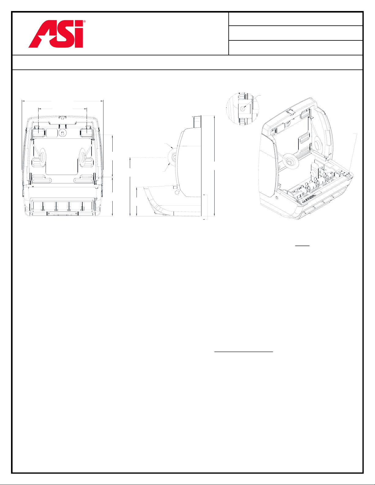
1. The supplied electrical utility box is fastened with two (2) #8 - 32 x 3/8" pan-head screws (supplied) into the
threaded weld nuts provided in the cabinet enclosure (see Fig. 4).
2. A licensed electrician can install the remaining industry standard components to the electrical supply per local
codes.
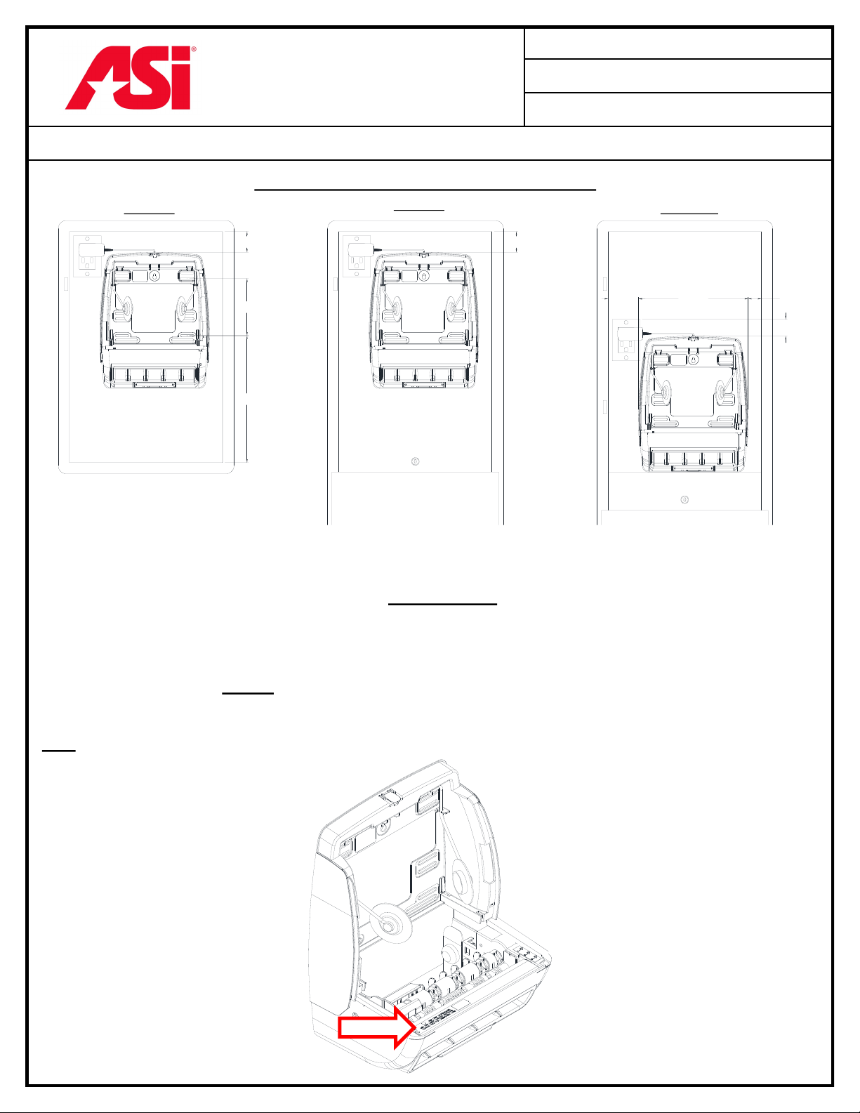
3. The AC/DC transformer wire jack end is plugged into a socket located in the lower right corner of the towel
mechanism unit (when viewed from front). The socket is hidden facing to the back (Fig. 5). Loosen the towel
mechanism mounting bolts slightly and tuck the loose wire inside the hollow plastic frame of the mechanism, up
the right side, across the top to where the transformer is plugged into the electrical outlet. This will keep it from
getting tangled in the towel rolls during operation. Retighten mounting screws and remove all installed batteries
before electric power is supplied .
8374
17 JUN 2017
17 AUG 2020
AUTOMATIC ROLL TOWEL MECHANISM OWNER’S MANUAL (Pg 4 of 7)

AMERICAN SPECIALTIES, INC.
441 Saw Mill River Road, Yonkers, NY 10701
(914) 476.9000 • (914) 476.0688
www.americanspecialties.com
MODEL №:
ISSUED:
REVISED:
THIS MANUFACTURER RESERVES THE RIGHT TO MAKE CHANGES IN DESIGN OR DIMENSIONS WITHOUT FORMAL NOTICE
Single Roll Loading
1. Place roll onto wire holders. Paper is to be loaded with paper end unwinding from the back of the roll as
shown in Fig. 6 above.
2. Paper end is then placed under the transfer bar arm as identified by arrow in Fig. 6, step 1 above.
3. Close and lock the cabinet door. The LED indicator light located at the top right corner of the paper chute will
flash one time to indicate the unit is powered up and ready to dispense. Test dispenser .
Automatic Transfer (Stub Roll) Loading
1. Transfer 4" diameter [Ø102] (or smaller) stub roll from wire holders (Fig. 7, step 1) without removing paper
from rollers to the stub roll holders located in the bottom back of the mechanism and the Stub Roll Paper
Monitor must be positioned over the stub roll paper web without any wrinkles in the web, as indicated by
arrow in Fig. 7, step 2 above.
2. Install new full paper roll into wire holders (Fig. 7, step 3) with paper end unwinding from the back of the roll
and place the paper end on TOP of the Stub Roll Paper Monitor & UNDER the tr ansfer bar ar m as shown
in Fig. 7, step 3 above. Paper from the new roll will automatically feed when the stub roll of paper runs out.
Fig. 6
PAPER ROLL LOADING & STUB ROLL FEATURE INSTRUCTIONS
8374
17 JUN 2017
17 AUG 2020
AUTOMATIC ROLL TOWEL MECHANISM OWNER’S MANUAL (Pg 5 of 7)
Fig. 7

AMERICAN SPECIALTIES, INC.
441 Saw Mill River Road, Yonkers, NY 10701
(914) 476.9000 • (914) 476.0688
www.americanspecialties.com
MODEL №:
ISSUED:
REVISED:
THIS MANUFACTURER RESERVES THE RIGHT TO MAKE CHANGES IN DESIGN OR DIMENSIONS WITHOUT FORMAL NOTICE
MECHANISM CONTROL SETTINGS
There are three (3) three-position switches available to customize the control system (Fig. 8). These switches are
on the right, inside corner of the mechanism. Once the cabinet door is closed, and the paper is loaded correctly,
the unit is ready to dispense at the factory default settings: normal dispense mode, nominal 12" [305] paper length,
and a 1 second delay between dispenses. NOTE: It may take about 3 dispenses for the mechanism to self-adjust to
the nominal paper length.
Switch #1 allows for the selection of a unique, patent pending Paper Saving dispense control method. In this
method, any dispense that occurs within 3 seconds of a previous dispense will result in a sheet dispense length that
is shorter than the initial dispense. In the Maximum Paper Saving position (MAX), the second sheet will be 25%
shorter than the initial dispense. In the Minimum Paper Saving position (MIN), the second dispense will be 12%
shorter than the initial dispense.
Switch #2 allows for three different time delays between dispenses. The three preset options are 3 (LONG), 2
(MEDIUM), and 1 (SHORT) second time delay.
Switch #3 allows for three different sheet dispense lengths to be chosen: nominal 15" [381] (LONG), nominal
12" [305] (MEDIUM), or nominal 9" [229] (SHORT).
8374
17 JUN 2017
17 AUG 2020
AUTOMATIC ROLL TOWEL MECHANISM OWNER’S MANUAL (Pg 6 of 7)
Fig. 8

AMERICAN SPECIALTIES, INC.
441 Saw Mill River Road, Yonkers, NY 10701
(914) 476.9000 • (914) 476.0688
www.americanspecialties.com
MODEL №:
ISSUED:
REVISED:
THIS MANUFACTURER RESERVES THE RIGHT TO MAKE CHANGES IN DESIGN OR DIMENSIONS WITHOUT FORMAL NOTICE
TROUBLESHOOTING
8374
17 JUN 2017
17 AUG 2020
AUTOMATIC ROLL TOWEL MECHANISM OWNER’S MANUAL (Pg 7 of 7)
SYMPTOM DIAGNOSTICS & SOLUTIONS
Unit will not activate at all
Make sure batteries (if using) are in the battery com-
partment and in the correct configuration as shown in
the graphics engraved inside the battery compartment.
Make sure AC plug is plugged into one of the utility
box outlets and Ø2 plug is fully engaged into socket
(see Figs. 4 and 5) on rear of the mechanism & verify
that 100-240VAC is provided to duplex outlet.
Clear any/all obstructions that are too close to the unit
(within 12" [305] of any side).
Unit runs but paper does not dispense
Make sure the paper is set up correctly in the mecha-
nism (see page 5 - Paper Roll Loading & Stub Roll
Feature Instructions).
Unit runs continuously or cycling on/off
Ensure there are no intermittent power surges on the
AC line from other equipment on same circuit. (AC
operation)
LED indicator light flashing continuously
(approx. every 1.5 seconds)
Low battery indicator. Replace batteries.
Automatic stub roll transfer does not
start new roll
Check and/or reposition Stub Roll Paper Monitor arm
and transfer bar arm.
Eliminate any wrinkles in the paper web.
Table of contents
Other ASI Dispenser manuals

ASI
ASI EZ FILL Product manual

ASI
ASI 0388 User manual

ASI
ASI EZFILL 0394 Series Product manual

ASI
ASI FS-0500 User manual

ASI
ASI 0390 Product manual

ASI
ASI 0363 User manual

ASI
ASI EZFILL 0391 Series Product manual

ASI
ASI EZFILL 0393 Series User manual

ASI
ASI EZ-Fill 10-0390 Configuration guide

ASI
ASI EZ FIL 0390-(n) User manual