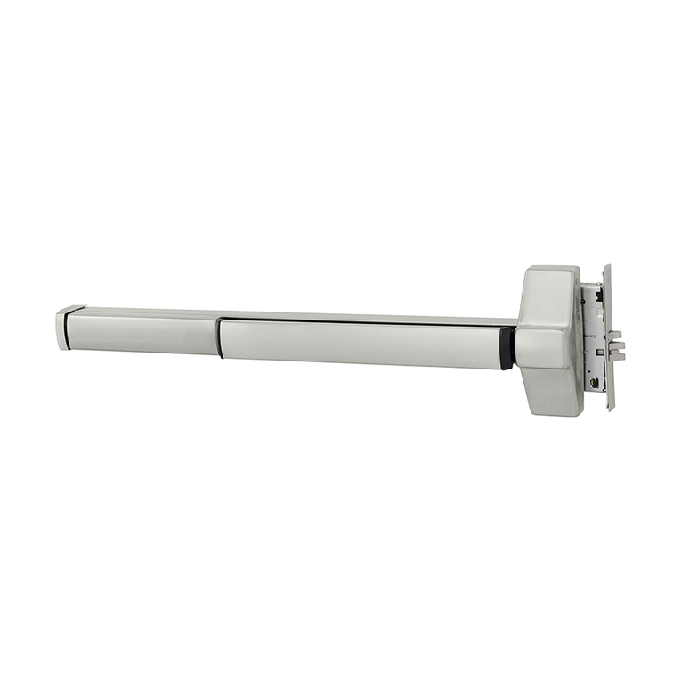
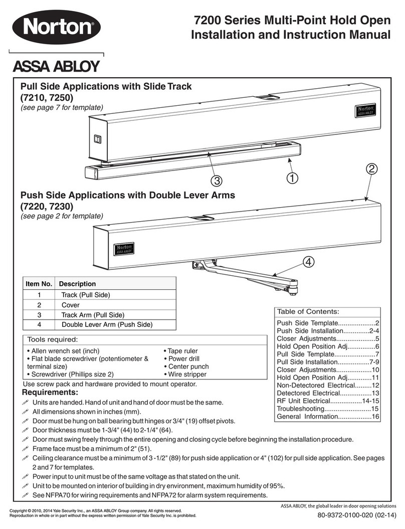
Assa Abloy Norton 7970DPS-B Series User manual
Other Assa Abloy Door Opening System manuals
Assa Abloy
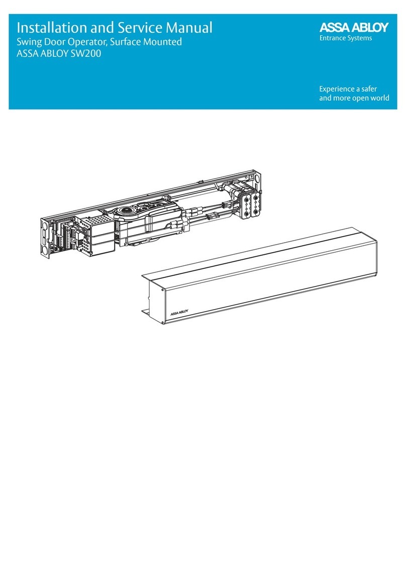
Assa Abloy SW200 Manual
Assa Abloy
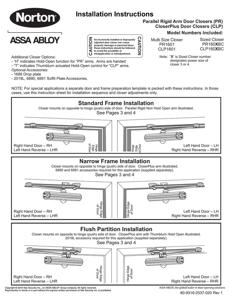
Assa Abloy Norton PR1601 User manual
Assa Abloy
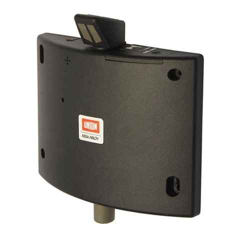
Assa Abloy UNION DoorSense 8755A User manual
Assa Abloy
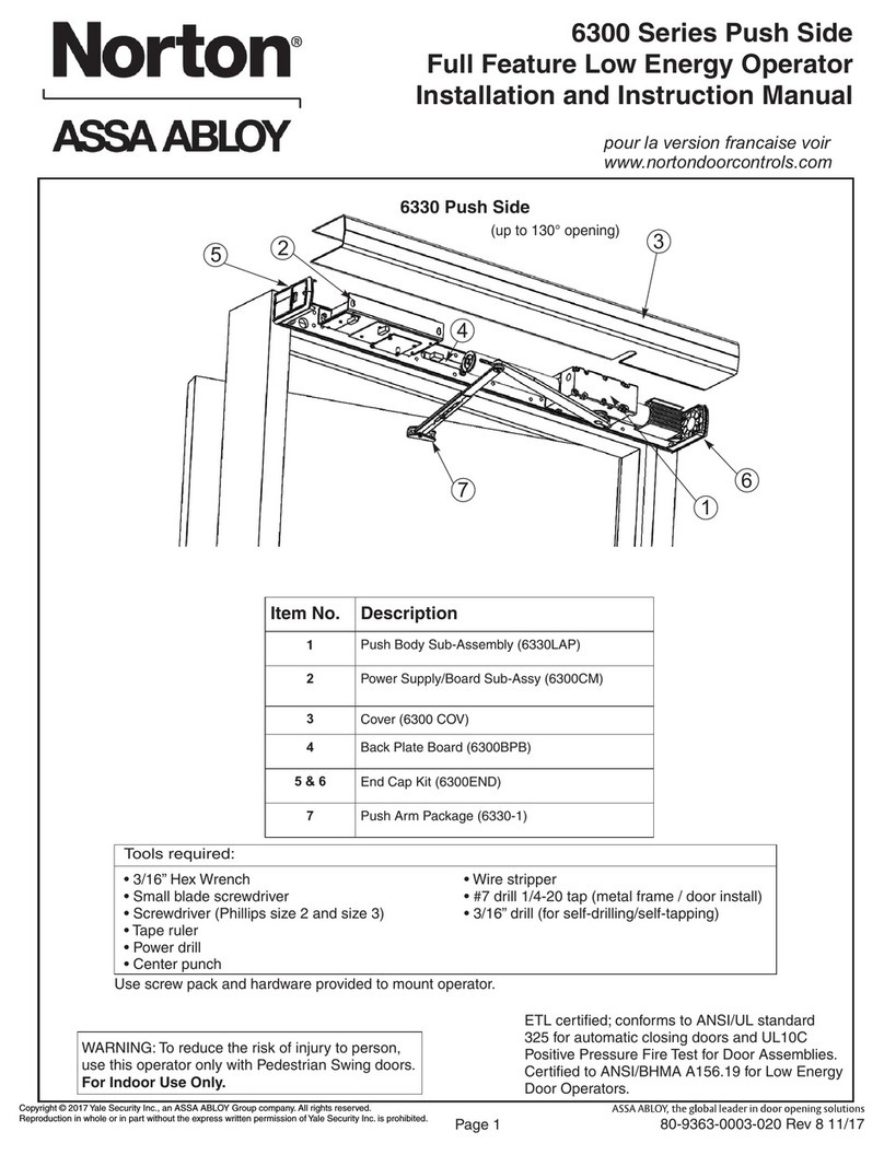
Assa Abloy Norton 6300 Series Quick guide
Assa Abloy
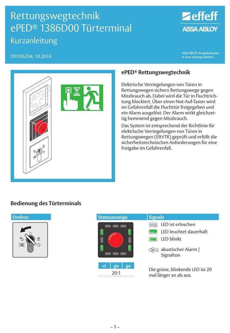
Assa Abloy effeff ePED 1386Z1LB7 04S0 Series Reference guide

Assa Abloy
Assa Abloy Besam SW200i User manual
Assa Abloy
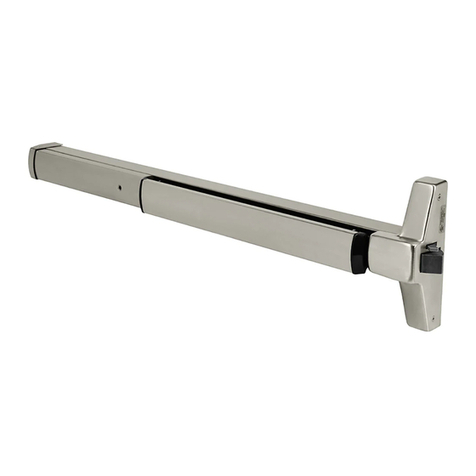
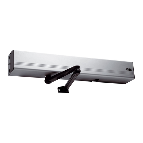
Assa Abloy Corbin Russwin ED4000 Series User manual
Assa Abloy
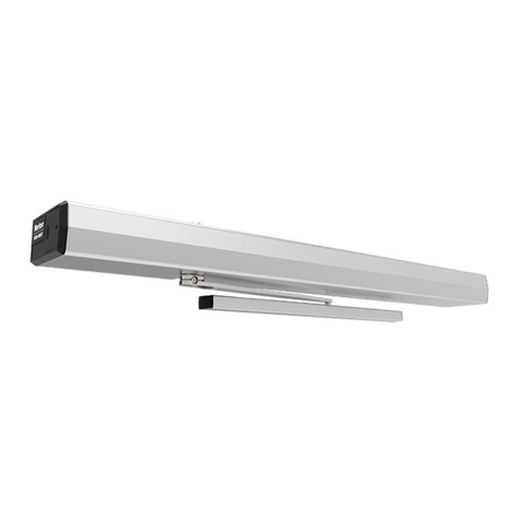
Assa Abloy SW100 User manual
Assa Abloy
Assa Abloy NORTON RIXSON 6200 Series User manual

Assa Abloy
Assa Abloy Norton 1600 Series User manual
Assa Abloy
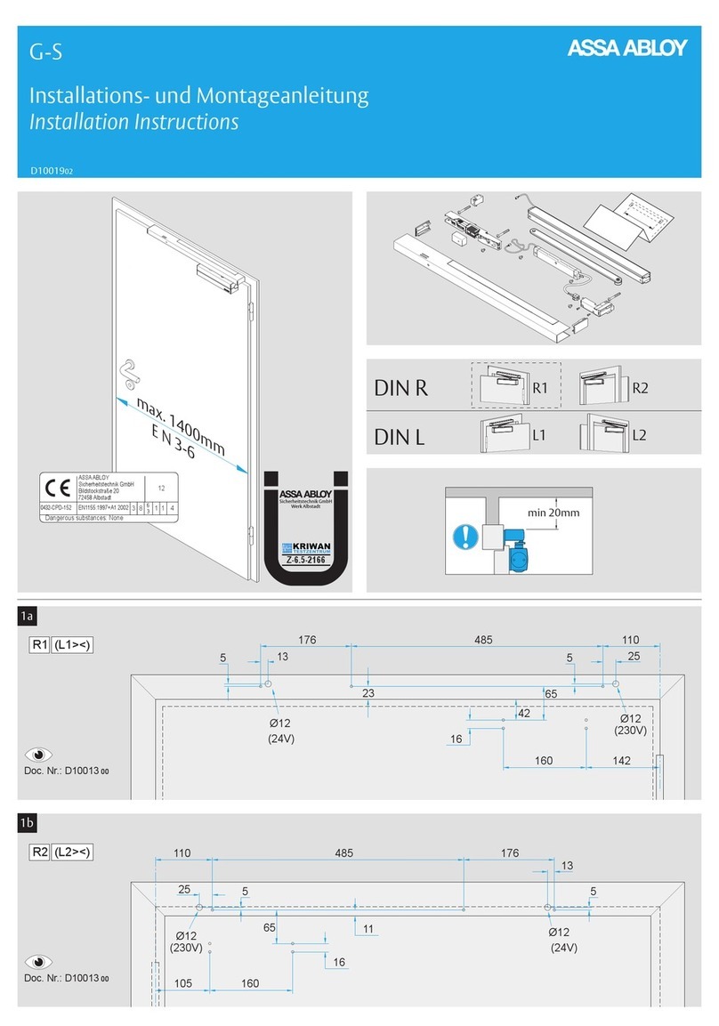
Assa Abloy G-S User manual

Assa Abloy
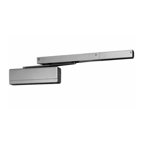
Assa Abloy Norton CloserPlus CLP8101 User manual
Assa Abloy
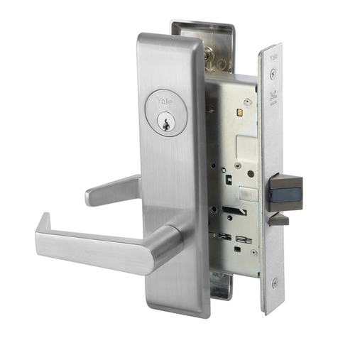
Assa Abloy SARGENT FIREGUARD 12-2468 User manual
Assa Abloy
Assa Abloy SARGENT 8800 Series Instruction Manual

Assa Abloy
Assa Abloy h.e.s. 9100 Series Manual
Assa Abloy
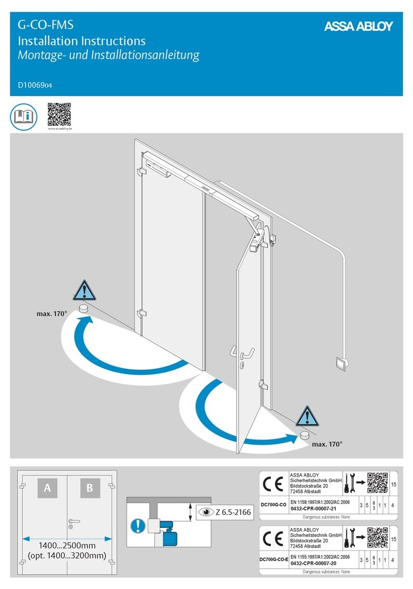
Assa Abloy G-CO-FMS User manual
Assa Abloy
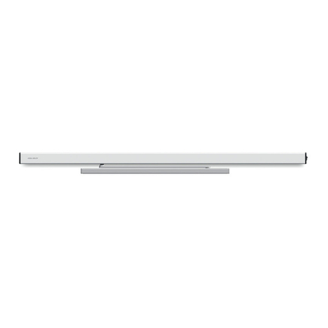
Assa Abloy SW60 User manual
Assa Abloy
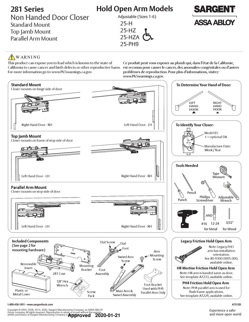
Assa Abloy SARGENT 281 Series User manual

Assa Abloy
Assa Abloy SARGENT 1431 Series User manual

Assa Abloy
Assa Abloy Corbin Russwin DC8200 Series User manual
Popular Door Opening System manuals by other brands

Stanley
Stanley MA900ñ Installation and owner's manual

WITTUR
WITTUR Hydra Plus UD300 Instruction handbook

Alutech
Alutech TR-3019-230E-ICU Assembly and operation manual

MPC
MPC ATD ACTUATOR 50 ATD-313186 Operating and OPERATING AND INSTALLATION Manual

GEZE
GEZE ECturn user manual

Chamberlain
Chamberlain T user guide
